
AMIKONG EXCESS CONTROL SYSTEM PARTS
Specializing In:Automation Spares(DCS, PLC, CNC) Servo Drives HMI Power supplies Controllers
-
Please try to be as accurate as possible with your search.
-
We can quote you on 1000s of specialist parts, even if they are not listed on our website.
-
We can't find any results for “”.
SEE PRODUCTS IN SEARCH PAGE ()
Continues to innovate and is committed to improving the supply level of discontinued automated parts. No matter where the customer is, no matter how rare the required parts are, we can always connect customers with the products they need.
Contact to Get Quote Now:


All Manufacturers
-
Please try to be as accurate as possible with your search.
-
We can quote you on 1000s of specialist parts, even if they are not listed on our website.
-
We can't find any results for “”.
SEE PRODUCTS IN SEARCH PAGE ()
- Select
-
ABBAccutracAcopianAC TechAction InstrumentsAdamAdaptecAdvanced Input DevicesAdvanced Micro ControlsAEGAISAlcatelAllen-BradleyAllied Telesis3MAlstomAMCIAntex ElectronicsApparatebau HundsbachArray ElectronicAseaASTECAutomation DirectAydin ControlsB&RBalluffBanner EngineeringBarco SedoBartecBECKBeierBeijer ElectronicsBently NevadaBerthelBiviatorBlack BoxBlockBofors ElectronikBoschBraunCEAG3COMCromptonCrouzetControl TechniquesCTI-Control Technology IncCutler-HammerDanfossDEC - Digital Equipment CorpDelta Computer SystemsDelta ElectronicsDigitalDigitronicsDuragDynaparEATONEBELTEberleElliot AutomationEmersonEndress HauserEntrelec SchieleERMAEurothermFanucFarnellFEASFestoFinder VaritecFischer PorterForney EngineeringFuji ElectricGalil Motion ControlGeneral ElectricGildemeisterGordosGrayhillGrenzebach ElectronicsHartingHedin TexHEIDENHAINHelmholzHIMAHirschmannHitachiHoneywellIBHsoftecIBMidecIDSIFM ElectronicINATINIVENIntelInvensysJAQUETJetter AGKentKEPCOKettnerKieback & PeterKlockner MoellerKnielKoyoKrauss MaffeiKuhnkeLambdaLandis GyrLauerL&N - Leeds & NorthrupLenzeLeukhardt SystemsLG GoldSecLittlefuseLumbergLutzeMagnecraftMannesmannMatsushitaMean WellMeasurement SystemsMeasurexMEDARMicro Innovation AGMicron Control TransformersMitsubishiMolexMoogMTL Insturments GroupMTSMurr ElektronikNAISNECNetstalNeumannOmega EngineeringOmronOpto 22Orbitran SystemsPANALARMPepperl + FuchsPesterPhilipsPhoenix ContactPilzPlasmaPotter & BrumfieldRed LionReis RoboticsReliance ElectricRexrothRIS - RochesterRonanSAE ElektronikSAIASATT ControlSauterSchaffnerSchieleSchildknechtSchiller ElectricSchleicherSchneider ElectricSchrack TechnikSelectronSensyconSEWSixnetSpectrum ControlsSprecher + SchuhSPS TechnologiesSquare DStahlSTI - Scientific Technologies, Inc.Struthers-DunnSysMikTaylorTecnint HTETelemecaniqueTimontaToshibaTransition NetworksTR ElectronicUnicompUniOPVibro-MeterVIPAVisoluxWachendorff AdvantechWagoWeidmullerWestronicsWielandWöhrleWolfWoodwardYokogawaZiehl-AbeggXycomEprobachmannSaftronicsSiemensKEBOpti MateAristaMKSMatrixMotortronicsMetso AuttomationProSoftNikki DensoK-TEKMotorola VMEForce Computers IncBerger LahrICS TriplexSharp PLCYASKAWASCA SchuckerGrossenbacherBremerMolex WoodheadAlfa LavalSiemens RobiconPerkinsProfaceSupconCarlo GavazziDEASSTHollysysSOLIDSTATE CONTROLSETEKOPTEKKUKAWHEDCOindramatMiscellaneous ManufacturersTEKTRONIXRorzeDEIFSIPOSTICS TRIPLEXSHINKAWAANYBUSHVAGERMAN POWERKONTRONENTEKTELSYSTEMKOLLMORGENLAZERPRECISION DIGITALLUBRIQUIPINCNOKIASIEI-GefranMSA AUER MUTKEBAANRITSUDALSALoad SharerSICKBradSCHENCKSTAIGER MOHILOENTERASYSUSB-LGTRSBIOQUELLSCHMERSALCORECOKEYENCEBIZERBABAUERBAUERCONTROLPACIFIC SCIENTIFICAPPLIED MATERIALSNMBNIWeishauptWeinviewCISCOPARKERLenovoKONECRANESTURBULHMSHOFFMANHUTTINGERTDK-LambdaRESOLVERKnickATLASGAMXTDKCAMERONNSKTamagawaGIDDINGS & LEWISBENDERSABOWOODHEADFRICK YORKSHENLERBALDORLam ResearchNTN BEARINGETAWEST INSTRUMENTSTDK-LambdaFireyeDAHUATESCHACROSSERFLUKESanyo DenkiBruel & KjaerEPSONHIOKIMettler ToledoRAYTEKEPCOSDFISEMIKRONHuaweiINDUSTRONICASI-HVEBARTEC POLARISAMATGD BolognaPrecise AutomationRADISYSZEISSReveal ImagingSaiernicoASEMAdvantechANSALDOELproMARCONIEBMPAPSTROTORKKONGSBERGSOCAPELTAIYOSUNYorkKURODAADLINKNotifierHBMInfineonLNICSaipwellJIANGYIN ZHONGHEW.E.ST. ElektronikEXPODEEP SEA ELECTRONICSBECKHOFFBOMBARDIER TRANSPORTATIONDragerZENTRO ELEKTRONIKATOSTRSystemtechnikJDS UniphaseADEPTREOPanametricsXenusSIGMATEK DIASS.C.E ElettronicaEKFETELSTOBER POSIDYNHANSHINDDKEITZENBERGERLTI MOTIONXP PowerPanasonicMatroxSBS TechnologiesWARTSILAMURPHYMADOKAArcnet DanpexLittelfuseTACANHurcoSAMGONGALPHALuxcoNautibusPAWO SystemsHaver&boeckerVAISALAConsiliumSERIPLEXMTUALPHIOPTIMATION INCNTRONTMEIC GLOBALBAUMERSANYO-DENKISeicaISE ReiterSealICP ELECTRONICSAxiomtekBautzSonosysVaconNematronWatt DriveSieb & MeyerDanaher MotionDEMAGDigifasDivusBühlerRMV ELECTRONICSOno SokkiOrbotechPLATING ELECTRONICNORD NORDACCircuit LineBergesAIENSNSZMCHATILLONACS GROUPADVANTESTSekidenkoDOLDTURCKAPI ControlsASAHI KEIKIQUALIFLOWASMLASTROCOGNEXContecESTICFishmanIAITeleFrankInternixAUMAPROVIBTECHK-TRONLemforderIXYSALERTONMOXASCIYONBASLER ELECTRICIntraActionVATDelta tauEMGHENGSTLERWESTERMODeutsmann AutomationCUMMINSBihl+WiedemannDAIKINJoppichPOUNDFULLEINE LINDEDELIXICompressor Controls CorporationMCHJENAER ANTRIEBSTECHNIK
-
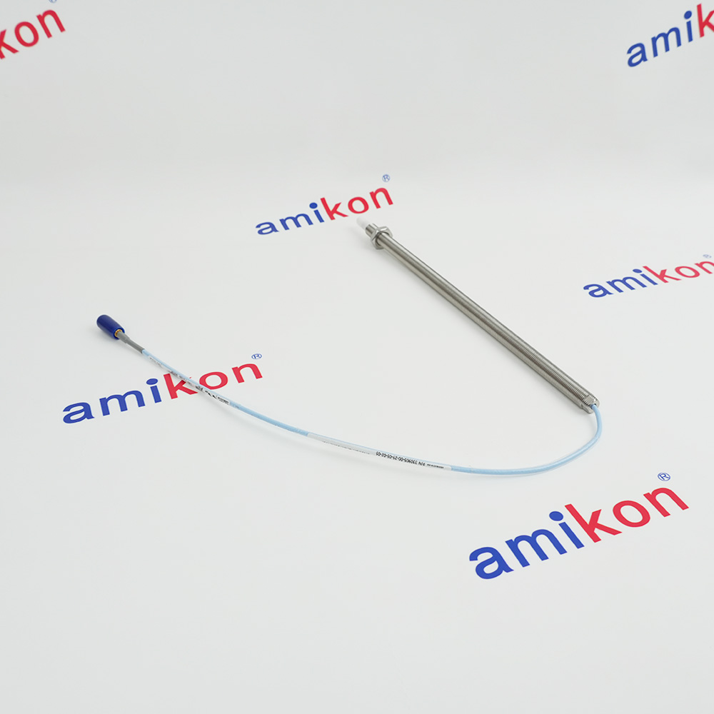
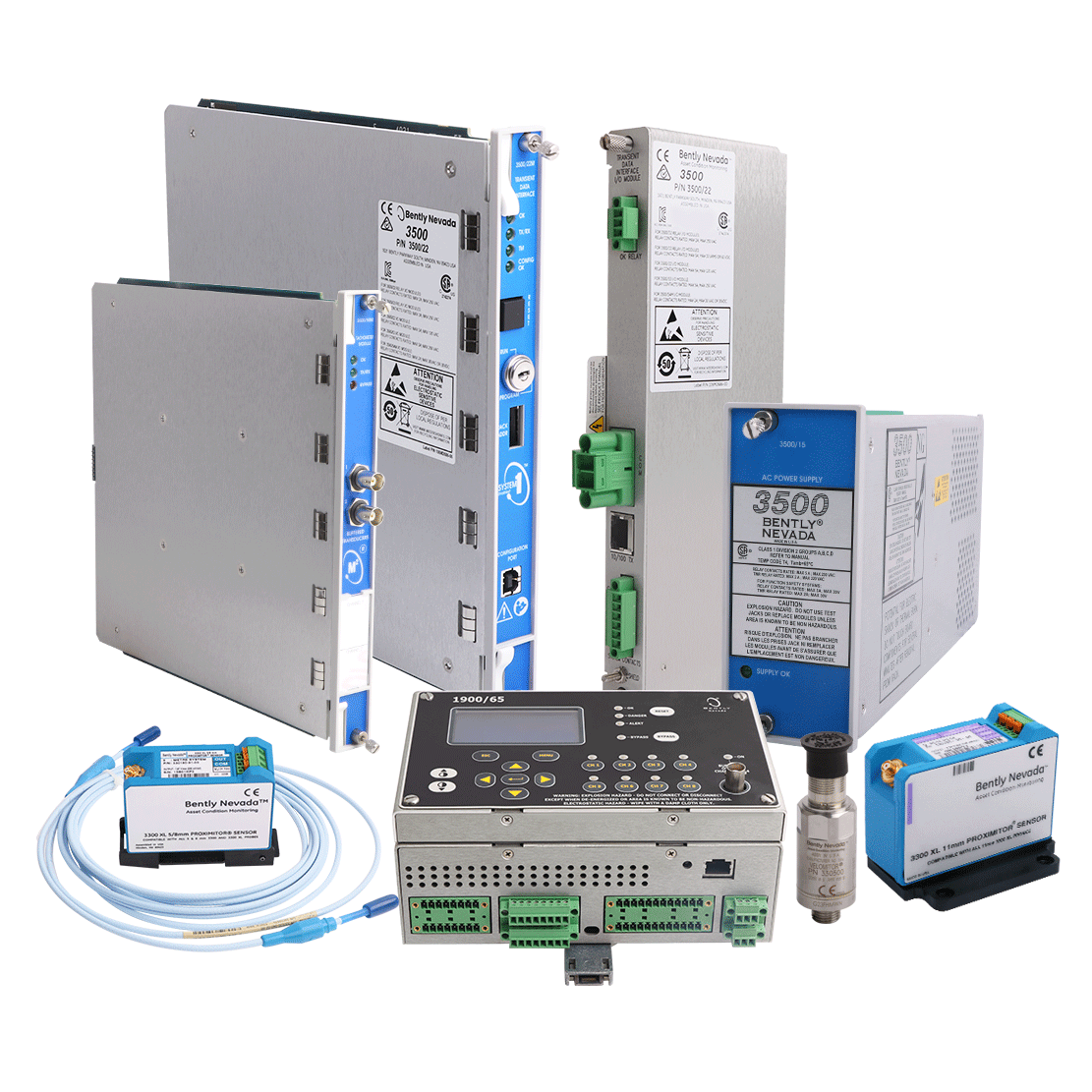
 3300 XL 8 mm Proximity ProbesManufacturer: Bently Nevada
 -
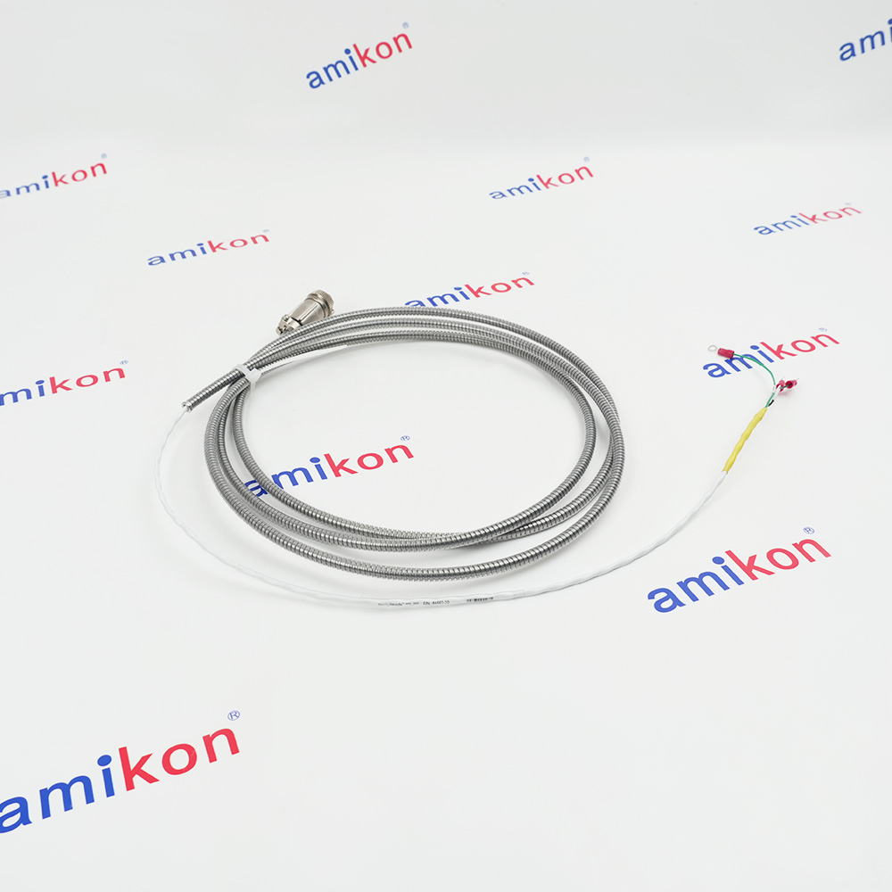
 Velomitor Interconnect CableManufacturer: Bently Nevada
 -
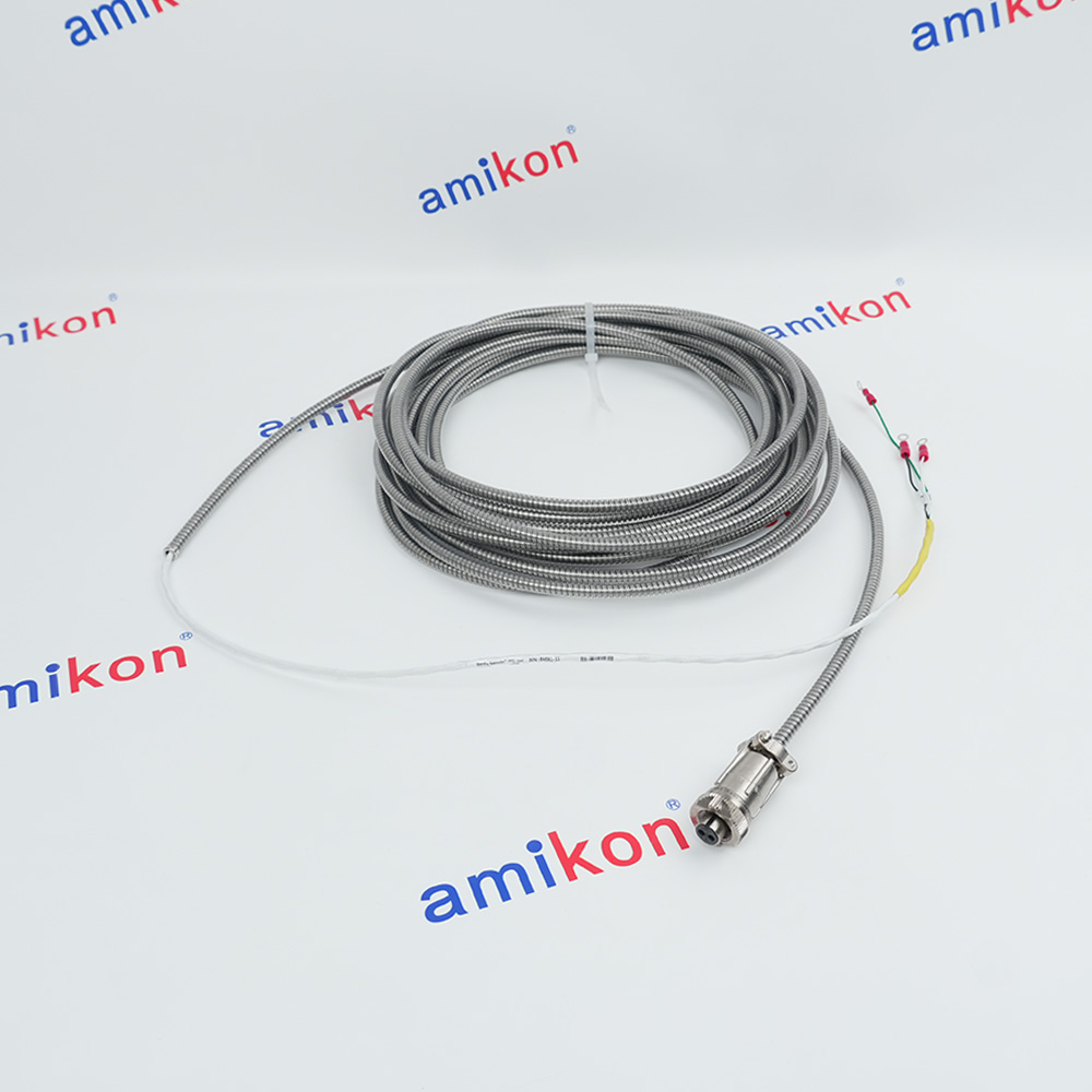
 3300 NSv Proximity ProbesManufacturer: Bently Nevada
 -
3300 NSv Proximity ProbesManufacturer: Bently Nevada
-
3300 NSv Proximity ProbesManufacturer: Bently Nevada
-
3300 XL Standard Extension CableManufacturer: Bently Nevada
-
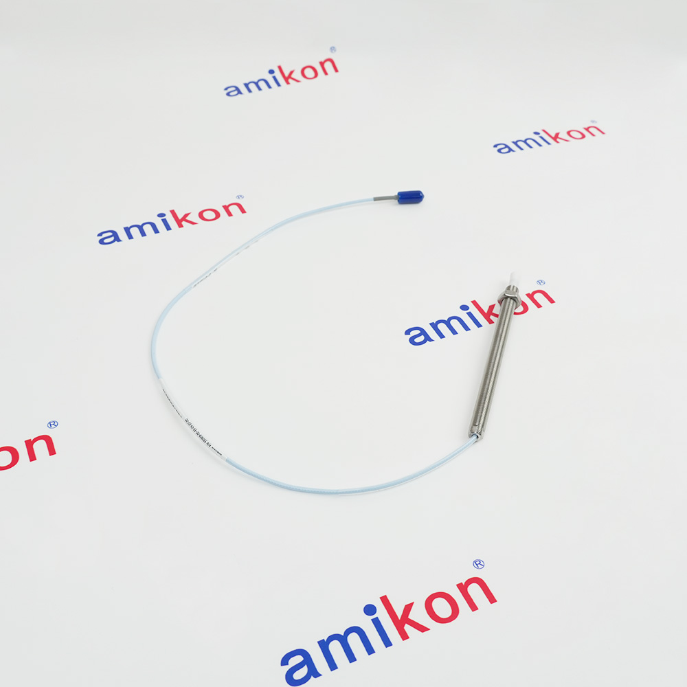
3300 NSv Extension CableManufacturer: Bently Nevada
-
 3300 NSv Extension CableIn StockManufacturer: Bently Nevada
 -
3300 NSv Proximity ProbesManufacturer: Bently Nevada
-
991 Thrust TransmitterManufacturer: Bently Nevada
-
3300 NSv Proximity ProbesManufacturer: Bently Nevada
-
Interconnect CableManufacturer: Bently Nevada
-
3300 XL 8 mm Proximity ProbesManufacturer: Bently Nevada
-
3300 XL Standard Extension CableManufacturer: Bently Nevada
-
 3300 NSv Proximity ProbesManufacturer: Bently Nevada
 -
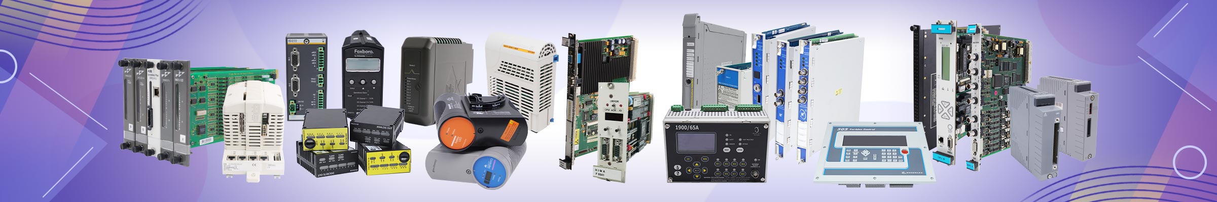
 Standard ArmoredInterconnect CableManufacturer: Bently Nevada
 -
3300 XL Standard Extension CableManufacturer: Bently Nevada
-
3300 XL Standard Extension CableManufacturer: Bently Nevada
-
3300 XL 8 mm Proximity ProbesManufacturer: Bently Nevada
-
3300 XL 8 mm Proximity ProbesManufacturer: Bently Nevada
-
990 Vibration TransmitterManufacturer: Bently Nevada
-
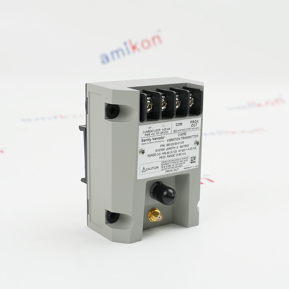 990 Vibration TransmitterManufacturer: Bently Nevada
 -
3300 XL 11 mm Proximity ProbesManufacturer: Bently Nevada
-
3300 XL 11 mm Extension CableManufacturer: Bently Nevada
-
3300 XL 11 mm Proximity ProbesManufacturer: Bently Nevada
FAQs
-
How do I submit a part enquiry?
+Our Product Pages – Simply search for the part number you require in our search bar, and it will take you straight to the product page. You can email or call us – Speak directly to a dedicated Account Manager, who will be able to answer any questions you have and provide you with a quotation within minutes -
How long is my quotation valid for?
+According to the inventory situation of the product, quotation are valid for 15 to 30 days from the day the quote is received, unless stated otherwise at the time of quotation. -
Why can't I see a price for a part?
+In addition to new units we also specialize in the selling discontinued and hard to find industrial automation parts which tend to have a fluctuating market value. These fluctuations may make it difficult for us to provide accurate daily prices for parts on our website. Therefore, in an effort to ensure that we always provide you with the best and most accurate price available, our team will source and price your part on an enquiry-by-enquiry basis. -
Do you offer global delivery services?
+Yes. We ship globally, and we are able to quickly deliver parts globally to any corner of the world. Unless otherwise specified, we will ship your order via (DHL). We can also ship through FedEx, UPS, and TNT. We can also use your account. -
How long will it take for my product to arrive?
+We understand the importance of speed in a critical breakdown situation, so wherever possible, we strive to dispatch parts within 1-3 days as an order is placed. However, each case is dealt with personal basis, and factors such as the condition or source of the parts can affect our operational speed. All details relating to the delivery timescale will be made very clear on your quotation. -
What payment options and currencies do you accept?
+To make your purchase as easy as possible, we provide the main method is bank wire transfer, and we can accept payments in most major world currencies; we can accept payments in most major world currencies; however, we do prefer payments to be made in US dollar (USD), pound sterling (GBP) or euro (EUR), where possible. Payments made in other currencies may be subject to additional charges. -
How many parts do you have in stock?
+We have an extensive stock base consisting of ten thousands of new and discontinued automation parts including those from leading manufacturers such as: Control Systems (DCS, PLC, TSI, CNC) Panel Controllers HMI and Display Panels Drives Power Supplies If you are unable to find what you are looking for then don’t panic. We collaborate -
Who can I contact if some problems occur?
+Our experienced Customer Support Team are on hand to help with any problems or questions that you may have once you have placed an order. The direct contact information for your Customer Support supervisor can be found on the bottom of your order confirmation. -
Amikon Limited Optimal Price Policy
+At Amikon Limited , we strive to provide customers with greater discounts on industrial automation parts prices.From time to time, another company may offer products at lower prices. If you happen to find a better price, please give us a matching opportunity. We will make every effort to match it!


- Q&A
- Policies How to order Part status information Shipping Method Return Policy Warranty Policy Payment Terms
- Asset Recovery
- We Buy Your Equipment. Industry Cases Amikong News Technical Resources Why choose us
- ADDRESS
-
 32D UNITS,GUOMAO BUILDING,NO 388 HUBIN SOUTH ROAD,SIMING DISTRICT,XIAMEN