


Close Menu
Get Parts Quote
Name
Company *
WhatsApp / WeChat (For Faster Quote) *
Email *
Address
City
State / Province / Region
Zipcode
Country
Quantity *
Part Number *
Manufacturer
Preferred Condition
Additional Information
Cancel
2026-10-19 11:25:43
10 min read

Bently Nevada 2300/20 to DCS: Check Loop Power Before Wiring

About the Reviewer
Sandy Lin
Sandy Lin's linkedin:

Sandy Lin - Amikon Gorden Partner
With 15+ year experience in automation parts supply, Sandy has served over 8,000 clients, achieving an 85% satisfaction rate. The supplied products are applied in government departments, involving various fields such as petrochemicals, metallurgy, steel, wind power, hydropower, aviation, packaging and transportation, etc. Her professional services and rapid response have earned it a highly praised reputation in the automation industry.She can perceive market changes, provide timely solutions to customers, and achieve sustainable long-term cooperation.
AMIKONG · TECHNICAL ARTICLEFN-2300-DCS

Bently Nevada 2300/20to DCS

Check loop power before wiring.A 4–20 mA label defines the signal range. It does not prove electrical compatibility.
2 outputsinternally powered
0–600 Ωdocumented load
0–12 Vcompliance
4–20 mAselected measurement

A correct local vibration value can still reach the DCS as an underrange alarm, a frozen number or a signal that stops rising before full scale.

Bently Nevada identifies DCS interfacing as a use of the 2300/20 configurable current output. This review addresses transfer of a selected measurement through 4–20 mA, not full-waveform diagnostic data.

Before replacing the monitor or changing calibration, establish which device supplies power to the current loop. Confirm that the selected DCS connection accepts a powered current output, then check burden, grounding and configuration.

Review boundaryThis is an engineering review and troubleshooting framework. It is not a terminal wiring instruction or permission to disturb machinery protection.
01 / OUTPUT

Start with the exact output specification.

The 105M0340 Rev. AD datasheet specifies two internally powered current outputs for the 2300/20 and excludes an externally powered loop. Output variable selection is configurable; the default clamp is 2 mA and can be changed. Output feedback determination is unavailable. The 2300/25 instead has an SPA interface.

Internalloop power source
600 Ω maxtotal documented load
12 V maxavailable compliance
2 mAdefault configurable clamp

Do not infer output type from a familiar connector, an old cabinet drawing or a spare described only as “2300.” Read the complete nameplate and compare the exact replacement with the installed configuration.

02 / POWER

Identify the power source at the actual terminals.

The useful question is whether the chosen receiving terminals inject loop power. A powered backplane does not automatically make every analog input unsuitable. Conversely, terminals intended to power a two-wire transmitter can introduce a second supply.

Obtain the DCS card number, terminal-base number, wiring diagram and channel mode. Trace marshalling links, barriers, isolators and any cabinet supply. Vendor terms such as “active” and “passive” are not consistent enough for approval.
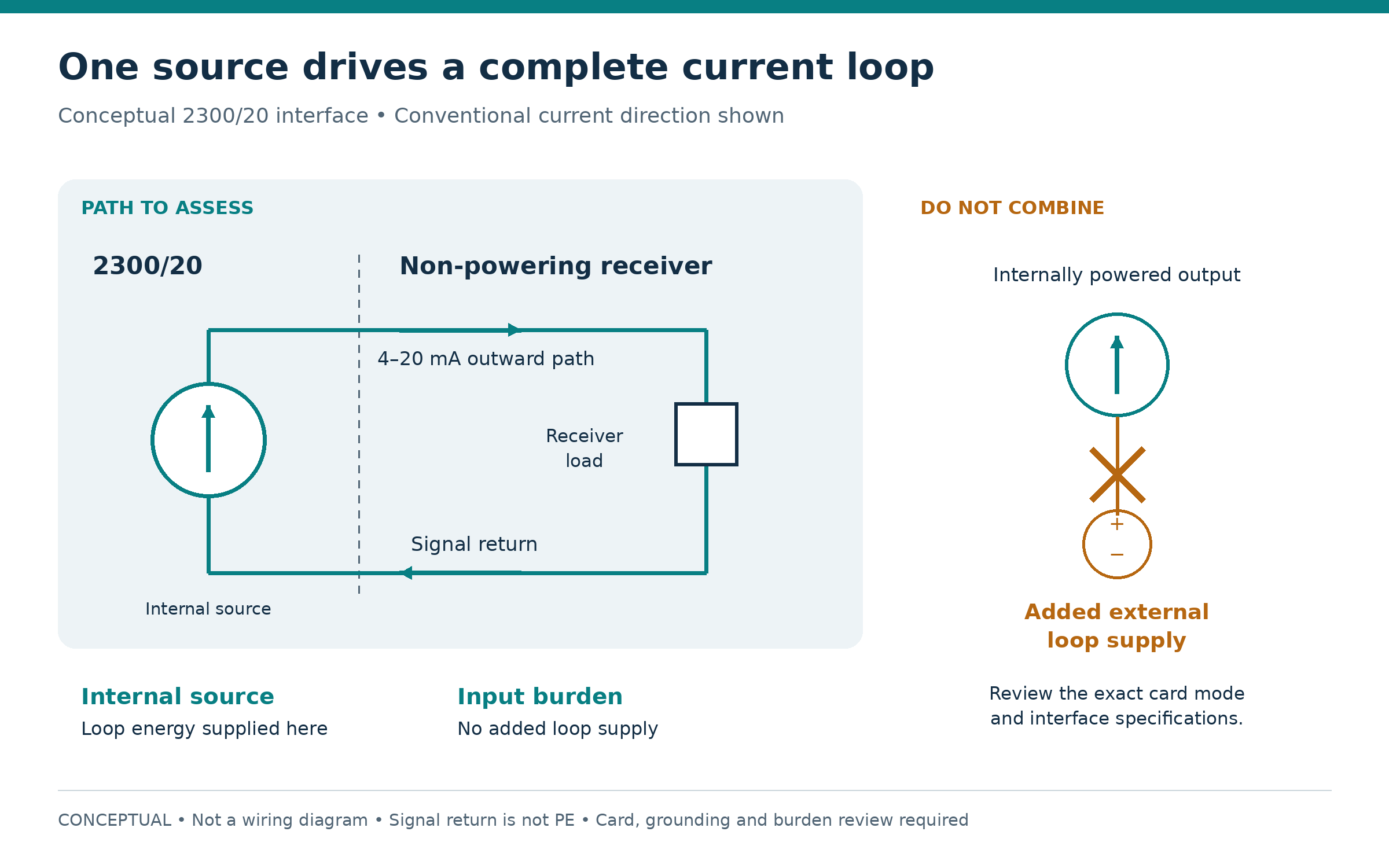
Conceptual 2300/20 current loop showing one internal source, a non-powering receiver and a warning not to add an external loop supply
Figure 1. A complete signal loop has an outward path and a return. The internal source supplies loop energy; the receiving path must not add loop power. Conceptual only, not a wiring diagram. Use exact equipment manuals and site-approved safe conditions.

If the card manual documents a suitable non-powering receiving path, assess that path against all remaining requirements. If the only approved receiving path supplies loop power, specify an interface with a suitable non-powering input and a compatible output. An isolator still requires review of burden, power arrangement, isolation, grounding, accuracy, response, fault transfer and area approval.

03 / BURDEN

Calculate the complete voltage burden.

A current source needs voltage to force current through the total loop load. Include the receiver, both cable conductors, terminals and every series component. Use documented maximum values where available, including temperature effects.
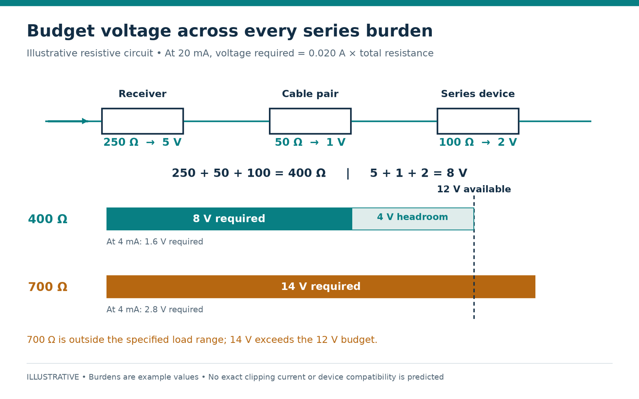
Voltage burden comparison showing a 400 ohm loop requiring 8 volts with 4 volts headroom and a 700 ohm loop requiring 14 volts
Figure 2. Illustrative series burdens consume 8 V at 20 mA, leaving 4 V of the 12 V budget. A 700 Ω load would require 14 V. Conceptual calculations, not an installation design or a prediction of clipping.
Use V = I × R only for resistive elements.Devices specified by voltage drop need a voltage-budget calculation. Leave practical margin and include temporary test instruments that add series burden.
04 / SYMPTOMS

Let the fault pattern guide the next check.

Zero current / severe underrange

Check continuity, polarity, terminals, protection devices and receiving configuration. Do not add cabinet power as an experimental cure.

Steady low current

Compare actual current with the configured clamp and channel status. Preserve the distinction between diagnostic current and valid vibration.

Tracks low, flattens high

Investigate compliance headroom, interface limits and output saturation. Compare requested value, measured current and loop burden.

Plausible but consistently wrong

Check selected variable, channel, range, units and amplitude convention: RMS, peak and peak-to-peak are different.

Correct current, wrong display

Inspect DCS raw scaling, range handling and display limits before replacing field hardware.

Intermittent behavior

Time-correlate raw input, quality flags, switching and maintenance. Review return paths, shield termination and isolation.

05 / PROOF

Prove each part of the path under an approved plan.

Establish consequences for trips, interlocks, alarms and operations before opening a loop or applying a test signal. Preserve the current configuration, identify the exact path, define authorization and restoration, and stop at documentary review if a safe test state cannot be established.
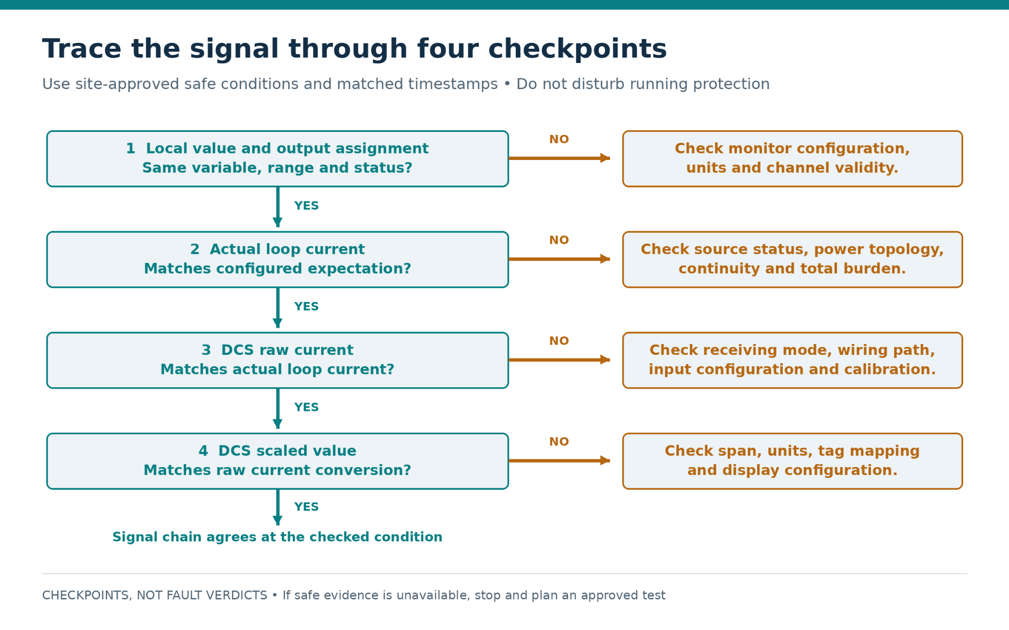
Four-step diagnostic flow comparing monitor configuration, actual loop current, DCS raw current and DCS scaled value
Figure 3. Follow the signal from local configuration through actual current, DCS raw input and scaling. A mismatch identifies a checkpoint to investigate, not a proven fault. Obtain evidence only under site-approved safe conditions.
  1. Prove the receiving path separately with a correctly configured calibrator. Source and simulate modes are not interchangeable.
  2. Verify monitor-side transfer using the applicable OEM procedure and approved known conditions.
  3. Compare monitor measurement, independent current, DCS raw input and engineering value at several points.
  4. Verify approved fault indications separately from normal scaling, then record as-found and as-left settings.

For an illustrative 0–25 mm/s range, 4, 12 and 20 mA correspond to 0, 12.5 and 25 mm/s. These are examples, not a prescribed monitor configuration. The conversion is lower range + [(current − 4 mA) ÷ 16 mA] × engineering span.

PRODUCTS

Related Amikong product pages.

Ask for written confirmation of the offered part number, condition, lead time, warranty, inspection and documents. Final installation suitability remains subject to the applicable OEM documents and the responsible site engineer’s approval.

FAQ

Common interface questions.

Can the 2300/20 connect directly to a DCS analog input?

Potentially, after the exact receiving connection is verified for power behavior, burden, polarity, common-mode limits and grounding. Matching 4–20 mA ranges alone is insufficient.

Does a powered DCS card always require an isolator?

No. Card power and loop power are different questions. Use the installed card and terminal-base diagram to identify whether the chosen signal connection injects field power.

Why does a successful 4 mA check not prove the loop?

Voltage demand rises with current. Low-end success can conceal a high-end limit and says little about span, selected variable or fault handling.

Should low diagnostic current be scaled as negative vibration?

Normally it should trigger the defined quality and fault handling. Establish the configured diagnostic behavior and DCS thresholds before interpreting it.

Can the two outputs be combined to feed one input?

Do not parallel current outputs. If several destinations require the same signal, review an approved distribution interface and define failure behavior.

Does a correct monitor reading prove delivery to the control room?

No. Verify actual current and the DCS raw value to separate an output-path problem from scaling or tag configuration.

Can a replacement be selected from the connector alone?

No. Match the full model, options and required output function, then review configuration and approvals.

What should be included in an article-specific enquiry?

Send the complete 2300/20 option code, DCS card and terminal-base identifiers, quantity, destination, required date, nameplate photographs and the specific loop-power question.

AMIKONG PRODUCT ENQUIRY

Send the complete loop identity.

Provide the monitor model and option code, a clear nameplate photo, DCS card and terminal-base identifiers, proposed diagram, units, configured ranges, quantity and required-by date.

Technical sources

  1. Baker Hughes / Bently Nevada — 2300/20 and 2300/25 Vibration Monitors, Datasheet 105M0340 Rev. AD. DCS application on printed page 1; output specifications on printed page 5.

The DCS receiving-card discussion is a general engineering review principle, not a statement that the 2300/20 is paired with a specific DCS manufacturer. Check the official manual for the exact installed DCS card and terminal base. The circuit calculations and diagnostic sequence are illustrative and do not represent a tested customer installation.


AMIKONG KNOWLEDGE HUBBently Nevada 2300/20 · DCS interface review

Keep your system in play!

Select
ABB
Accutrac
Acopian
AC Tech
Action Instruments
Adam
Adaptec
Advanced Micro Controls
AEG
Alcatel
Allen-Bradley
3M
Alstom
AMCI
Apparatebau Hundsbach
Array Electronic
ASTEC
Automation Direct
B&R
Balluff
Banner Engineering
Barco Sedo
Bartec
BECK
Beier
Beijer Electronics
Bently Nevada
Biviator
Black Box
Bosch
Braun
CEAG
Crouzet
Control Techniques
CTI-Control Technology Inc
Cutler-Hammer
Danfoss
DEC - Digital Equipment Corp
Delta Computer Systems
Delta Electronics
Digital
Digitronics
Durag
EATON
EBELT
Eberle
Emerson
Endress Hauser
Entrelec Schiele
Eurotherm
Fanuc
Farnell
Festo
Finder Varitec
Fischer Porter
Forney Engineering
Fuji Electric
General Electric
Grayhill
Harting
Hedin Tex
HEIDENHAIN
Helmholz
HIMA
Hirschmann
Hitachi
Honeywell
IBM
idec
IDS
IFM Electronic
INAT
Intel
Invensys
JAQUET
Jetter AG
Kieback & Peter
Klockner Moeller
Koyo
Kuhnke
Lambda
Landis Gyr
Lauer
L&N - Leeds & Northrup
Lenze
Leukhardt Systems
LG GoldSec
Littlefuse
Lumberg
Magnecraft
Mannesmann
Matsushita
Mean Well
Measurement Systems
Measurex
MEDAR
Micro Innovation AG
Micron Control Transformers
Mitsubishi
Molex
Moog
MTL Insturments Group
MTS
Murr Elektronik
NAIS
NEC
Omega Engineering
Omron
Opto 22
Orbitran Systems
PANALARM
Pepperl + Fuchs
Philips
Phoenix Contact
Pilz
Red Lion
Reliance Electric
Rexroth
RIS - Rochester
Ronan
SAE Elektronik
SAIA
Sauter
Schiele
Schildknecht
Schiller Electric
Schleicher
Schneider Electric
Schrack Technik
Selectron
SEW
Spectrum Controls
Sprecher + Schuh
Square D
Stahl
STI - Scientific Technologies, Inc.
SysMik
Taylor
Tecnint HTE
Telemecanique
Toshiba
Transition Networks
TR Electronic
UniOP
Vibro-Meter
VIPA
Visolux
Wachendorff Advantech
Wago
Weidmuller
Wöhrle
Woodward
Yokogawa
Ziehl-Abegg
Xycom
Epro
bachmann
Saftronics
Siemens
KEB
Opti Mate
Arista
MKS
Motortronics
Metso Auttomation
ProSoft
Nikki Denso
K-TEK
Motorola VME
Force Computers Inc
Berger Lahr
ICS Triplex
Sharp PLC
YASKAWA
SCA Schucker
Bremer
Molex Woodhead
Alfa Laval
Siemens Robicon
Proface
Supcon
Carlo Gavazzi
SST
Hollysys
SOLIDSTATE CONTROLS
ETEK
OPTEK
KUKA
WHEDCO
indramat
Miscellaneous Manufacturers
TEKTRONIX
Rorze
DEIF
SIPOS
SHINKAWA
ANYBUS
HVA
GERMAN POWER
KONTRON
ENTEK
TEL
SYSTEM
KOLLMORGEN
LAZER
PRECISION DIGITAL
LUBRIQUIPINC
NOKIA
SIEI-Gefran
MSA AUER MUT
KEBA
ANRITSU
DALSA
Load Sharer
SICK
Brad
SCHENCK
STAIGER MOHILO
ENTERASYS
USB-LG
TRS
BIOQUELL
SCHMERSAL
CORECO
KEYENCE
BIZERBA
BAUERBAUER
CONTROL
PACIFIC SCIENTIFIC
APPLIED MATERIALS
NMB
NI
Weishaupt
Weinview
CISCO
PARKER
KONECRANES
TURBUL
HMS
HOFFMAN
HUTTINGER
TDK-Lambda
RESOLVER
Knick
ATLAS
BENDER
SABO
BALDOR
Lam Research
NTN BEARING
ETA
WEST INSTRUMENTS
TDK-Lambda
Fireye
DAHUA
TESCH
ACROSSER
FLUKE
Sanyo Denki
Bruel & Kjaer
EPSON
HIOKI
Mettler Toledo
RAYTEK
EPCOS
DFI
SEMIKRON
Huawei
INDUSTRONIC
ASI-HVE
BARTEC POLARIS
AMAT
GD Bologna
Precise Automation
RADISYS
ZEISS 
Reveal Imaging
Saiernico
ASEM
Advantech
ANSALDO
ELpro
MARCONI
EBMPAPST
ROTORK
KONGSBERG
SOCAPEL
TAIYO
SUN
York
KURODA
ADLINK
Notifier
HBM
Infineon
LNIC
Saipwell
JIANGYIN ZHONGHE
W.E.ST. Elektronik
EXPO
DEEP SEA ELECTRONICS
BECKHOFF
Drager
ZENTRO ELEKTRONIK
ATOS
TRSystemtechnik
JDS Uniphase
ADEPT
REO
Panametrics
Xenus
SIGMATEK DIAS
S.C.E Elettronica
EKF
ETEL
STOBER POSIDYN
HANSHIN
DDK
EITZENBERGER
LTI MOTION
XP Power
Panasonic
Matrox
SBS Technologies
WARTSILA
MURPHY
MADOKA
Arcnet Danpex
Littelfuse
TACAN
Hurco
SAMGONG
ALPHA
Luxco
Nautibus
PAWO Systems
Haver&boecker
VAISALA
Consilium
SERIPLEX
MTU
ALPHI
OPTIMATION INC
NTRON
TMEIC GLOBAL
BAUMER
SANYO-DENKI
Seica
ISE Reiter
Seal
ICP ELECTRONICS
Axiomtek
Bautz
Sonosys
Vacon
Nematron
Watt Drive
Sieb & Meyer
Danaher Motion
DEMAG
Digifas
Divus
Bühler
RMV ELECTRONICS
Ono Sokki
Orbotech
PLATING ELECTRONIC
NORD NORDAC
Circuit Line
Berges
AIENSN
SZM
CHATILLON
ACS GROUP
ADVANTEST
Sekidenko
DOLD
TURCK
API Controls
ASAHI KEIKI
QUALIFLOW
ASML
ASTRO
COGNEX
Contec
ESTIC
Fishman
IAI
TeleFrank
Internix
AUMA
PROVIBTECH
K-TRON
Lemforder
IXYS
ALERTON
MOXA
SCIYON
BASLER ELECTRIC
IntraAction
VAT
Delta tau
EMG
HENGSTLER
WESTERMO
Deutsmann Automation
CUMMINS
Bihl+Wiedemann
DAIKIN
Joppich
POUNDFUL
LEINE LINDE
DELIXI
Compressor Controls Corporation
JENAER ANTRIEBSTECHNIK
MCGS
SMC
Load Cell Central
KFG LEVEL
Peripheral Control Systems Corporation
SanDisk
CHINT
Selinc
Eltek
AI‑Tek
HACH
POWER ONE
SIMTRONICS
SiliconDrive
Megger
CATERPILLAR CAT
KYLAND
DUNGS
Horner APG
EBG
LEM
AEREVB
APROTB
ATATVA
BROWN
Adlee
AGEIDA
AVG Automation
Get Parts Quote
Comments

Leave Your Comment

Company
* Email
* Mobile
* Content
Your email address will not be published
Newsroom

Related articles Browse All

  • Implementing Vision Systems for Industrial Robots: Enhancing Precision and Automation
    Blog
    2025-08-12 11:26:54
    Implementing Vision Systems for Industrial Robots: Enhancing Precision and Automation
    Industrial robots gain powerful new abilities through vision systems. These systems give robots the sense of sight, so they can understand and react to what is around them. So, robots can perform complex tasks with greater accuracy and flexibility. Automation in manufacturing reaches a new level of ...
  • Optimizing PM Schedules Data-Driven  Approaches to Preventative Maintenance
    Blog
    2025-08-21 18:08:33
    Optimizing PM Schedules Data-Driven Approaches to Preventative Maintenance
    Moving away from fixed maintenance schedules is a significant operational shift. Companies now use data to guide their maintenance efforts. This change leads to greater efficiency and equipment reliability. The goal is to perform the right task at the right time, based on real information, not just ...
  • The Evolution of Steam Turbine Control Systems
    Blog
    2026-03-31 08:33:35
    The Evolution of Steam Turbine Control Systems
    CALL US:+86-18020776786 | E-MAIL:INFO@AMIKON.CN In-depth analysis of the GE Mark VIe control system Mark VIe: A Modern Mainstay for Industry 4.0 Mark VIe's core concepts are "high availability, open connectivity, and intelligent readiness." It utilizes comm...