
-
Please try to be as accurate as possible with your search.
-
We can quote you on 1000s of specialist parts, even if they are not listed on our website.
-
We can't find any results for “”.
Drive Capacitor Failure Symptoms: Early Detection and Prevention
In every project where I am called in to “rescue” a misbehaving drive system, I look at the capacitors early. They rarely get the spotlight, but in low‑ and medium‑voltage variable frequency drives and power factor stages they quietly hold the DC bus together, tame ripple, and keep nuisance trips at bay. When they start to fail, the symptoms often look like “mystery” drive faults, random shutdowns, and flaky motors.
This article walks through what failing drive capacitors really look like in the field, how to catch problems early, and how to plan preventive action instead of waiting for a blown DC bus on a Friday night. The focus is practical, grounded in real drive service experience and supported by manufacturers and reliability sources such as ABB, EMA Inc., Cadence, Fluke, AIC Tech, and others cited below by name.
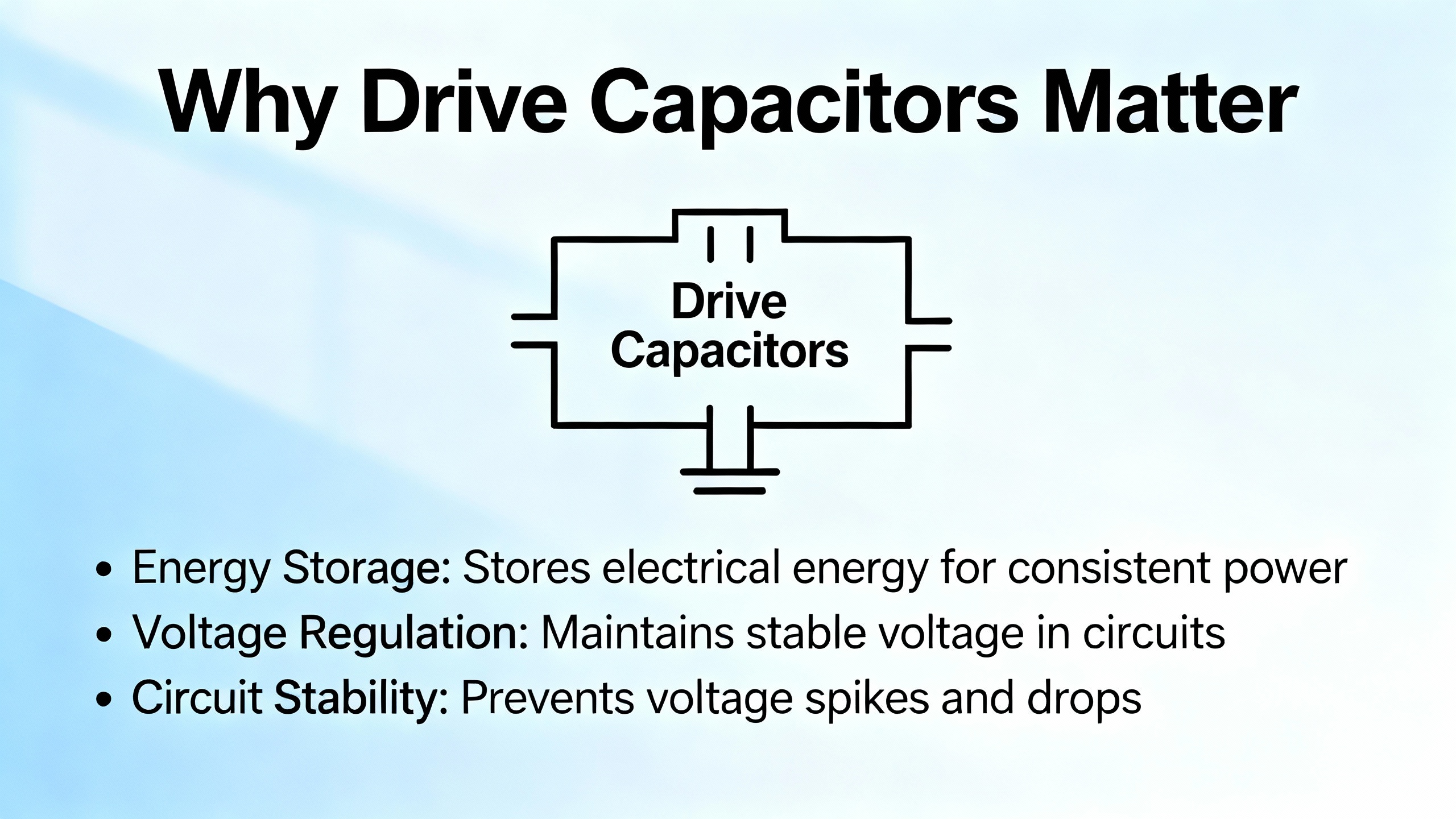
Why Drive Capacitors Matter
In a typical voltage‑source drive, the input rectifier charges a DC bus made from a bank of capacitors. Those capacitors smooth the rectified waveform, stabilize DC bus voltage, and limit ripple current before the energy is chopped by the inverter stage and sent to the motor. ABB makes the point very clearly in their guidance for ACS‑series drives: these capacitors are mission‑critical for stabilizing the DC bus, smoothing power delivery, and controlling electromagnetic interference.
When bus capacitors age or fail, you see a cascade of issues. DC bus faults and under‑ or over‑voltage alarms appear more often, drives overheat, and motors start misbehaving during acceleration and deceleration. EMA Inc., with several decades of medium‑voltage drive field work behind them, notes that electrolytic capacitors in drives and low‑voltage power supplies sit squarely in the seven‑ to ten‑year useful life range. Past that point, they become one of the highest‑risk items in the entire drive.
Film or oil‑filled capacitors in some medium‑voltage designs last longer, but even there, poor cooling, high ripple current, or dirty environments will bring service life down. In UPS systems and power factor banks, reliability engineers and power quality specialists report the same pattern: once capacitors drift out of spec, everything downstream has to work harder, energy losses climb, and the odds of a sudden outage go up sharply.
How Capacitors Fail in Drives
From a reliability standpoint, drive capacitors almost never “just die” at random. Their failure modes are well understood.
Electrolytic capacitors, which make up most low‑voltage DC bus banks, slowly lose electrolyte over time due to evaporation and chemical reactions. Cadence’s reliability work on electrolytic capacitors emphasizes that high temperature is the primary accelerator. As the electrolyte level drops and seals age, capacitance falls, equivalent series resistance (ESR) rises, and dissipation factor increases. The result is a part that runs hotter, filters less effectively, and is far closer to both open‑circuit and short‑circuit failure.
AIC Tech’s failure case library describes three main modes. Open failures, where impedance becomes very high, allow ripple to pass straight through into downstream circuits. Short‑circuit failures result from insulation breakdown and turn the capacitor into a resistive element with Joule heating proportional to current squared times resistance. Parametric failures are the ones we care most about for early detection: capacitance, ESR, leakage current, and loss drift outside their specifications long before anything explodes.
The whitepapers and design notes converge on the same root causes. Excess voltage stress, either from steady operation near the rating or repeated surges, pushes the dielectric toward breakdown. High ripple currents and excessive switching ripple raise internal temperature and accelerate electrolyte loss. Poor ventilation and blocked airflow trap heat in the drive enclosure. Vibration and mechanical shock crack internal connections and thin dielectric films. Humidity, contamination, and corrosive atmospheres creep past seals, corrode electrodes, and drive leakage current higher.
Even in seemingly benign applications like household fans and HVAC units, similar patterns show up. Engineers studying fan motor capacitors have watched capacitance fade until motors can no longer deliver torque, causing slowdowns and stalls. HVAC service providers report capacitors in compressors and blower motors failing from overheating, sun exposure, and environmental stress long before the rest of the unit is truly worn out.
Drive manufacturers and service firms treat all of this as predictable aging rather than bad luck. EMA Inc. compares long‑overdue capacitor replacement in medium‑voltage drives to running a car timing belt far beyond its recommended interval: it may keep going, but when it finally fails, the collateral damage is painful.
Early Electrical Symptoms Inside Drives
In a perfect world, we would always catch capacitor problems at the “soft” symptom stage, when the only hint is an alarm log that looks a little noisier than it did last year. In practice, this is exactly where smart monitoring and disciplined log review pay off.
On modern ABB drives, for example, the manufacturer provides dedicated capacitor health monitoring and trend data. The parameters behind those dashboards mirror what Cadence and other component specialists highlight as early indicators: slowly dropping capacitance, steadily rising ESR, and increasing dissipation factor. When those trends reach about a twenty percent deviation from rated values, the advice is to treat the capacitor as end‑of‑life even if the drive is still running.
In the field, aging capacitors typically show up first as DC bus anomalies and stability issues. Delta Automation’s work on ABB drive service notes that DC bus over‑voltage or under‑voltage alarms, especially during hard acceleration or deceleration, are key warning signs. As filtering degrades, the bus voltage swings more with line disturbances and regen events, and the drive is forced to trip in self‑defense.
Power quality specialists like Fluke see similar electrical signatures in power factor capacitor banks. They recommend trending phase currents and bus voltages over time. Imbalances between phases or unusual ripple on currents that used to be clean are often the first indication that one or more capacitors in a stage have weakened or failed open.
In adjustable speed drives, other electrical symptoms appear. Articles from IEN and experienced troubleshooters point out that degraded DC link capacitors can contribute to undervoltage trips when line sags occur, because the bus cannot ride through short dips the way it did when the capacitors were healthy. On the other side, over‑voltage trips occur more readily during braking and regenerative events, because the weakened bank cannot absorb energy spikes without crossing bus voltage limits.
Spiceworks community discussions and practical machinist forums echo the same pattern in real equipment. Technicians report random drive reboots, ground fault trips that clear when the drive cools, and drives that shut off instantly when power is removed, in contrast to similar units that stay powered for many seconds or a minute on stored energy. While design differences can certainly play a role, a drastic reduction in “hold‑up” time on a DC bus is a legitimate reason to investigate capacitor health.
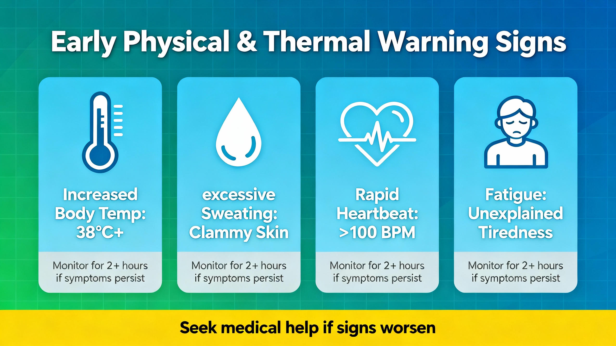
Early Physical and Thermal Warning Signs
The electrical symptoms are only half of the story. In my experience, most of the truly avoidable disasters were foreshadowed by simple visual or thermal cues long before the plant called for help.
Multiple sources, including ABB drive service notes, HVAC maintenance guides, and AIC Tech’s case studies, call out the same visual indicators. A bulging or domed top on an aluminum can capacitor is a classic sign of internal gas buildup and pressure. Cracked seals, oily or brownish residue, and clearly visible electrolyte leakage around leads indicate the part has already vented and is living on borrowed time. Discoloration of the sleeve or nearby PCB, charred markings, or warped plastic standoffs point to repeated overheating.
In ABB drives and similar equipment, abnormal enclosure temperature and drive thermal alarms are also closely tied to capacitor condition. As ESR rises, internal heating climbs, the capacitor runs hotter, and the temperature sensors in the drive begin to report higher internal temperatures even at familiar loads. EMA’s experience with medium‑voltage drives reinforces this: cooling fan failures and clogged filters quickly raise internal component temperature, dramatically accelerating capacitor aging.
AIC Tech documents a mechanical design error that blocked the pressure relief vent on a snap‑in aluminum electrolytic capacitor with a heat sink mounted too close to the top. During an over‑voltage event, the vent could not open as intended, pressure built, and the capacitor failed from the bottom in a much less controlled way. The lesson for integrators is simple: vent markings and clearance recommendations in datasheets are not decoration; they are safety features.
Audible changes also matter. Mode Comfort’s HVAC guidance, as well as McKinsey Electronics’ notes on motor capacitors, highlight humming, buzzing, or clicking near capacitor locations as potential signs of internal arcing, dielectric breakdown, or excessive ripple. When those noises appear along with reduced performance under load, capacitor health becomes a primary suspect.
Thermal imaging adds another layer. Fluke emphasizes scanning energized capacitor banks and drive panels with an infrared camera after they have been under load for at least an hour. Hot spots at terminal connections reveal high‑resistance joints; localized heating on a single can in a bank suggests abnormal loss in that part. In a balanced, healthy three‑phase bank, temperatures should be similar from phase to phase and stage to stage.
Early Versus Late Symptoms at a Glance
It can be useful to think of capacitor failures progressing through stages. The following table summarizes typical patterns in drive and power applications.
| Symptom or observation | Stage of failure | Risk if ignored |
|---|---|---|
| Slightly higher DC bus ripple and occasional alarms | Early degradation | Growing risk of nuisance trips |
| Gradual rise in drive internal temperature at same load | Early to mid | Accelerated aging of all components |
| Audible hum or EMI issues increasing over time | Mid | Increasing stress on motors and controls |
| Visible bulging, discoloration, or electrolyte stains | Late | High risk of short, venting, or fire |
| Frequent DC bus faults, over/under‑voltage trips | Late | High likelihood of sudden drive shutdown |
| Smoke, vent rupture, or ruptured cans | Catastrophic | Potential board damage and safety hazards |
In a well‑run plant, maintenance teams act firmly in the early and mid stages, long before anything on that last line becomes reality.
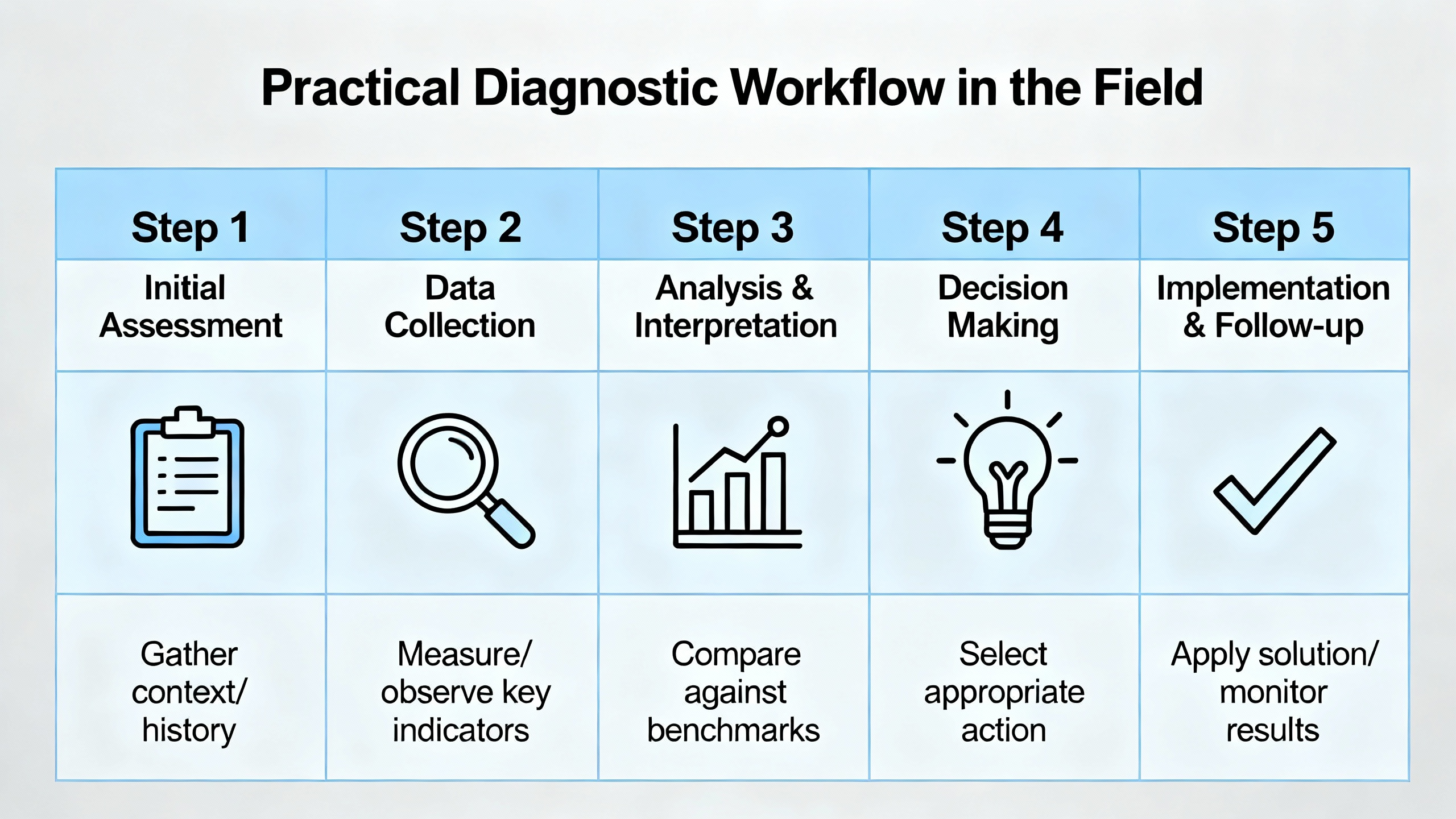
Practical Diagnostic Workflow in the Field
Over the years I have settled into a repeatable approach whenever a drive or capacitor bank shows suspicious behavior. The specifics change with the brand and voltage level, but the sequence is surprisingly consistent.
The first step is to interrogate the drive or power controller itself. On modern drives, I review the event history for DC bus over‑voltage, under‑voltage, or thermal alarms and note when they started. I then pull any internal health metrics the manufacturer provides, especially capacitor condition indicators and trend logs where available. ABB’s built‑in capacitor monitoring is a good example of what best‑in‑class OEMs now provide.
Next, I look at electrical measurements under real operating conditions. Using a power analyzer or drive analyzer, I record DC bus voltage, ripple, and line voltage for a full duty cycle, including startup, ramp to full load, and stop. IEN’s troubleshooting guidance reminds us to check three‑phase current and voltage imbalance as well. Even small voltage imbalances can cause large current differences, increasing heat in both motors and drive components, including the bus capacitors.
At the same time, I use infrared imaging to scan the drive enclosure and capacitor bank while energized. Fluke recommends that terminals and bus bars should not be significantly hotter than ambient plus a modest margin. Large phase‑to‑phase temperature differences or an isolated hot can in a bank go straight into the notebook as suspects.
Only after I have captured and analyzed these non‑invasive data do I consider direct testing of the capacitors themselves. When it is safe and appropriate, and only with lockout/tagout applied, I de‑energize the drive, verify with a meter that DC and AC voltages are truly at zero, and then discharge the DC bus with appropriate resistors or discharge tools. At that point, an ESR meter and a capacitance meter become valuable.
Delta Automation highlights ESR testing on de‑energized ABB drives as a primary diagnostic method, with elevated ESR indicating internal deterioration. Capacitance measurements are compared to the rated values from the nameplate or manual, and deviations greater than roughly twenty percent are treated as justification for replacement. These numbers align well with component manufacturer recommendations captured by Cadence: near the end of their useful life, electrolytic capacitors show a combination of reduced capacitance, increased ESR, and increased leakage current.
Visual inspection remains the final check. Following AIC Tech’s and Mode Comfort’s guidance, I inspect each capacitor can for bulging, cracked seals, stains, corrosion, and heat discoloration, and I examine nearby PCB areas for darkened resin or lifted traces caused by hot spots.
In complex power electronics, particularly high‑energy drives or UPS systems, McKinsey Electronics advises involving qualified specialists if there is any doubt about safe handling or replacement. The stored energy in large bus capacitors and power factor banks is not forgiving of guesswork.
Preventive Strategies: From Design to Maintenance
Once you understand how drive capacitors fail and how to detect the early symptoms, the next question is how aggressively to act. Different industries and facilities land in different places on the continuum between run‑to‑failure and fully planned replacement.
A vintage‑computer enthusiast writing for a hobbyist audience describes a “run‑until‑failure” strategy and argues that pre‑emptive recapping of old boards can be overdone. In that world, failure often means a single machine goes down and can be repaired at leisure. Drive systems in industrial plants are another story. EMA’s field experience with medium‑voltage drives and ABB’s own recommendations on capacitor replacement both support a planned approach: after about five years of operation or roughly twenty thousand operating hours, capacitor health should be tested; after seven to ten years, replacement should be strongly considered or scheduled, especially in harsh environments.
From a design perspective, several preventive principles stand out and are backed by both component physics and field data. First, manage temperature. Both Cadence and Quora‑summarized design guides for electrolytic capacitors stress that capacitor life is strongly temperature dependent. A common rule of thumb is that every significant drop in case temperature below the maximum rating roughly doubles life; expressed in imperial terms, a reduction of roughly eighteen degrees Fahrenheit from the top of the allowable range yields a substantial increase in service life. That is why EMA places so much emphasis on functioning cooling fans, clean air paths, and panel designs that respect the drive’s thermal rating.
Second, respect ripple and current ratings. AIC Tech’s case histories show that DC link capacitors exposed to ripple currents above their specification self‑heat, degrade insulation, and eventually short or vent. Power factor correction application notes from Fluke and power electronics guides from component vendors recommend checking expected ripple current and waveform against capacitor datasheets and selecting parts whose allowable ripple current meets or exceeds the worst‑case conditions.
Third, control over‑voltage and regenerative energy. Practical discussions of common drive failure modes in PowerFlex‑series drives note that roughly eight percent of failures in one field dataset were linked to poor input power quality, including voltage spikes from utility switching and line capacitors. Line reactors are recommended as relatively inexpensive protection against these transients and should not be dismissed as only harmonic filters. On the drive output side, misconfigured deceleration or insufficient braking hardware on overhauling loads can push regenerated energy back into the DC bus, raising voltage and stressing capacitors. Proper braking resistors or active front‑end designs need to be specified where loads frequently regenerate.
Fourth, protect against environmental and mechanical abuse. Jiukang’s discussion of capacitor aging and failure emphasizes that humidity, temperature cycling, and pollutants lower insulation resistance, encourage corrosion, and cut life short. Moisture‑proof packaging, conformal coatings on PCBs, and good enclosure design go a long way. Mechanical design must also respect mounting and vent clearance recommendations to avoid stress fractures and blocked relief paths.
On the maintenance side, routine inspection and testing should be baked into the drive maintenance plan rather than treated as an afterthought. ABB and several UPS and capacitor bank manufacturers advise including capacitor checks in standard semiannual or annual maintenance, with at least visual inspection and basic electrical checks for capacitance and leakage. EMA recommends in‑depth capacitor assessments and replacement planning for drives older than about ten years, particularly in medium‑voltage fleets where a single catastrophic failure carries wide consequences.
Finally, procurement quality matters. Spiceworks hardware discussions and capacitor selection guides converge on the same advice: choose drives and capacitor banks from reputable manufacturers, pay attention to the brands and series of capacitors used, and avoid the temptation to save a small upfront amount by accepting unproven components in critical paths. In my own projects, the difference in call‑out rates between installations with solid component choices and those that cut corners has been obvious.
Planning Replacement: Pros and Cons of Different Approaches
Maintenance managers often ask whether they should recap every drive on a fixed calendar schedule or wait for measured evidence of degradation. The answer depends on criticality, accessibility, and the quality of the monitoring at hand.
A purely time‑based replacement program is simple to administer. If you know that the electrolytic capacitors in your low‑voltage drives have a typical useful life of seven to ten years, replacing them at eight years regardless of condition provides a predictable budget line and eliminates a major variable. EMA’s recommendation to proactively replace capacitors in drives older than about ten years falls into this camp. The downside is obvious: you may replace some capacitors that still have useful life, and every intervention carries its own small risk.
A purely run‑to‑failure approach is attractive for non‑critical equipment and for organizations without strong maintenance discipline. You simply react when drives trip, leak, or bulge. The experience from ABB service teams, EMA field work, and HVAC service providers makes the trade‑off clear: you save on planned replacement, but you accept a higher probability of unplanned outages, collateral damage to boards, and emergency call‑out costs.
Most industrial facilities do best with a condition‑based program that sits between those extremes. Capacitor condition monitoring built into higher‑end drives, periodic ESR and capacitance testing on older units, regular thermal imaging, and disciplined alarm log review allow you to identify which drives are approaching end‑of‑life and prioritize them for replacement. Component reliability analyses from Cadence and Quora’s engineering discussions reinforce the idea that monitoring capacitance, ESR, and leakage gives actionable early warning long before safety vents open.

Short FAQ
How early can I realistically detect failing capacitors in drives?
In most modern drives you can see electrical signs years before a hard failure, provided you are looking. Gradual increases in DC bus ripple, more frequent over‑ or under‑voltage alarms during aggressive ramps, rising drive internal temperatures at unchanged loads, and early shifts in manufacturer‑reported capacitor health metrics are all early indicators. ESR and capacitance measurements that drift more than roughly twenty percent from nameplate values are a strong signal that replacement is warranted even if the drive has not tripped yet.
Can a single failed capacitor destroy an entire drive?
Field experience and hobbyist reports from other domains suggest that many capacitor failures are localized and fixable, especially when caught early. However, industrial drives operate at much higher energies than vintage computers or low‑power gadgets. A short‑circuit failure that generates intense heat, flames, or electrolyte spray can damage nearby components and copper, particularly if pressure relief paths are obstructed or if over‑current protection does not act quickly. The safest approach is to treat visible capacitor damage, strong odors, or smoke as immediate grounds for de‑energizing the equipment and investigating thoroughly before re‑energizing.
Is “recapping” an old drive always worth it, or should I just replace the whole unit?
It depends on the drive’s age, criticality, and overall condition. For a high‑value medium‑voltage unit where the power stage and control electronics are otherwise in good shape, replacing aging capacitor banks can extend life cost‑effectively, especially when guided by diagnostics and performed by specialists familiar with that brand. For small, low‑cost low‑voltage drives near or beyond their economic life, replacement of the entire unit is often more practical, particularly if there are no built‑in health diagnostics and spare parts are hard to source. In all cases, factor in downtime risk and safety considerations, not just component cost.
How often should we schedule capacitor testing in an industrial drive fleet?
A practical pattern, consistent with recommendations from ABB and EMA, is to begin including capacitor health checks in routine maintenance after about five years of service or roughly twenty thousand operating hours. For high‑criticality drives in harsh environments, ESR and capacitance testing every one to two years after that point is prudent. For lower‑criticality equipment in clean, cool environments, less frequent checks may suffice, especially if the drives provide internal health monitoring that is being actively reviewed.
Closing Thoughts
Drive capacitors rarely fail without telegraphing their intentions. If you treat the DC bus bank as a consumable asset, watch its electrical behavior, respect its thermal and electrical limits, and plan for its eventual replacement, you can remove a major source of unpleasant surprises from your plant. Speaking as a systems integrator who has stood in too many hot panels at inconvenient hours, a modest investment in early detection and preventive action around capacitors pays back quickly in uptime, safety, and trust from your operations team.

References
- https://emainc.net/5-things-that-cause-failures-in-your-medium-voltage-drives/
- https://www.3phi-reliability.com/blog/easy-capacitor-testing
- https://resources.pcb.cadence.com/blog/2022-the-causes-of-electrolytic-capacitor-degradation
- https://smart.dhgate.com/capacitor-failure-causes-modes-prevention-explained/
- https://www.jiukang.com/info/causes-and-preventive-measures-for-capacitor-a-102861434.html
- https://www.justanswer.com/appliance/2nqox-test-capacitor.html
- https://www.mckinsey-electronics.com/post/diagnosing-capacitor-failures-through-electrical-testing
- https://www.mouser.com/blog/avoid-these-common-capacitor-mishaps?srsltid=AfmBOoq8QY1kbXbVh7VuDNTPBTyLryu8T8fAc9DfvS4-cHmALO_R2NxB
- https://www.aictech-inc.com/en/valuable-articles/capacitor_troubleshooting01.html
- https://deltaautomation.com/blogs/news/abb-drive-capacitor-health-signs-of-trouble-and-proactive-testing-tips
Keep your system in play!
Top Media Coverage
Categories


Related articles Browse All
-
 amikong NewsSchneider Electric HMIGTO5310: A Powerful Touchscreen Panel for Industrial Automation2025-08-11 16:24:25Overview of the Schneider Electric HMIGTO5310 The Schneider Electric HMIGTO5310 is a high-performance Magelis GTO touchscreen panel designed for industrial automation and infrastructure applications. With a 10.4" TFT LCD display and 640 x 480 VGA resolution, this HMI delivers crisp, clear visu...
 -
 BlogImplementing Vision Systems for Industrial Robots: Enhancing Precision and Automation2025-08-12 11:26:54Industrial robots gain powerful new abilities through vision systems. These systems give robots the sense of sight, so they can understand and react to what is around them. So, robots can perform complex tasks with greater accuracy and flexibility. Automation in manufacturing reaches a new level of ...
 -
 BlogOptimizing PM Schedules Data-Driven Approaches to Preventative Maintenance2025-08-21 18:08:33Moving away from fixed maintenance schedules is a significant operational shift. Companies now use data to guide their maintenance efforts. This change leads to greater efficiency and equipment reliability. The goal is to perform the right task at the right time, based on real information, not just ...


- Q&A
- Policies How to order Part status information Shipping Method Return Policy Warranty Policy Payment Terms
- Asset Recovery
- We Buy Your Equipment. Industry Cases Amikong News Technical Resources Why choose us
- ADDRESS
-
 32D UNITS,GUOMAO BUILDING,NO 388 HUBIN SOUTH ROAD,SIMING DISTRICT,XIAMEN
Leave Your Comment