
-
Please try to be as accurate as possible with your search.
-
We can quote you on 1000s of specialist parts, even if they are not listed on our website.
-
We can't find any results for “”.
Siemens CPU Module Fault Diagnosis: Expert Troubleshooting Tips
When a Siemens CPU goes into fault, plant time evaporates. In my role as a systems integrator and project partner, I’ve been in those hot, noisy cabinets enough to know that winning the first ten minutes decides the next ten hours. The aim here is to help you diagnose CPU module and network-related faults quickly and confidently, with field-proven techniques grounded in reputable references such as Siemens Industry Online Support, Industrial Automation Co., ControlNexus/PLCVFD, the Inductive Automation forum, PLCTalk, and the Oxmaint community.
SF vs BF: Read the Story Your LEDs Are Telling
On Siemens platforms, the SF (System Fault) and BF (Bus Fault) indicators are not just warning lights; they are directional arrows. An SF in steady red points to internal CPU issues, faulty modules, or configuration mistakes. A BF in steady red points to communication trouble between nodes. Both can illuminate simultaneously, which nearly always means there are multiple layers to the failure. As a matter of practice, I begin with the CPU’s Diagnostic Buffer in STEP 7 or TIA Portal. That buffer is a timestamped truth serum, confirming the exact moment the PLC decided it had a problem and what it thought the problem was.
On Profibus systems, a solid red BF at the master doesn’t mean every node is down. It means at least one DP device is in trouble. The failure often clusters farther from the master when termination or cabling is marginal. If all nodes beyond a certain point show BF, you are likely staring at a mid-span terminator that’s been left ON, or a segment break. On Ethernet/PROFINET systems, BF can mask network pathologies elsewhere. Successful ping or even a TCP open means very little if a deep packet inspection firewall is resetting S7 traffic right after the handshake. That exact pattern has been observed in the field and discussed by practitioners on the Inductive Automation forum.

Start With the Physical Layer: Power, Grounding, and Cabling
Before chasing software ghosts, confirm your fundamentals. Power module issues masquerade as CPU trouble more often than teams expect, and a noisy or sagging 24 V DC can throw an entire I/O rack into intermittent faults. Keep a disciplined eye on grounding and equipotential bonding across cabinets. Several real-world cases reported by practitioners attribute intermittent “module mismatch” and random BF/SF events to degraded earthing and unexpected EMC coupling.
Cable health and termination are next. On Profibus DP, the termination resistors live inside the connectors. Only the physical endpoints of a segment should have termination enabled; every other connector should have termination switched off. Many sites operate Profibus reliably at about 1.5 Mbaud over spans around 50 yards, but marginal links sometimes stabilize only after reducing speed. Do not gloss over connector style and condition. Older screw-terminal and newer knife-type connectors both work, provided they are clean, strain-relieved, and properly shielded. A single connector swap has restored communications more than once, including a reported case where swapping connectors between two cabinets brought a dead segment back to life.

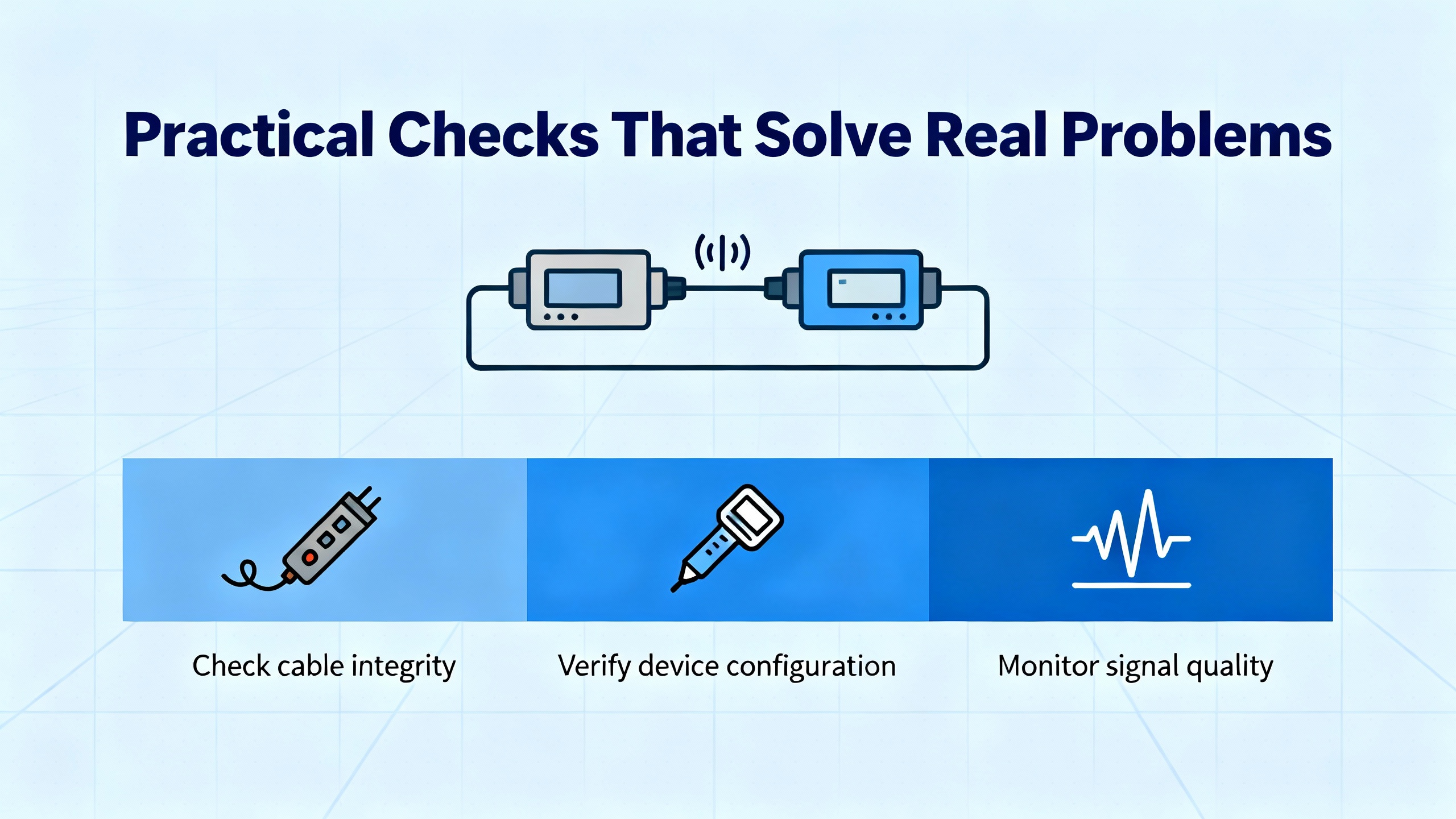
Profibus DP: Practical Checks That Solve Real Problems
Profibus troubleshooting rewards methodical isolation. Begin near the master. Confirm that node 1 is exactly what your project says it is, even if the LED is green. Verify the address, check the connector, and then validate the termination states. If the master’s BF is solid after you’ve reseated connectors and verified addressing, pull test steps into play.
One highly effective isolation technique is the IM swap. Move an IM151-3 from a failing remote I/O cabinet into the first cabinet, bring its Profibus and power across with it, and ensure you include the end resistor. Don’t change DIP switches or add I/O. Watch what the CPU reports. If the CPU sees the IM but flags it as faulty because configured I/O is missing, your basic bus path and connector at the first cabinet are fine. If the CPU still says the IM isn’t available, you likely have a different failure to chase. Pay attention to the specifics of your modules; for example, the 6ES7151-1AA04-0AB0 standard interface allows one missing I/O module before it refuses to go into RUN, and that nuance can save you from misinterpreting a “mismatch” as a wiring failure.
A word on addressing conventions helps, too. Many Profibus sites reserve address 1 for the CPU and 2 for the programming device, with remote racks starting at 3 or 4. Whatever scheme you inherit, enforce consistency and document it. On Profibus, address switches are latched on power-up, so cycle power after any change to avoid chasing phantom addresses.
When basic tools run out of road, dedicated bus analyzers earn their space in the toolbox. The Oxmaint community and experienced engineers regularly recommend Softing’s BC-700 or Procentec’s Profitrace for line quality checks, jitter analysis, and precise fault localization that STEP 7 may not surface.
PROFINET and Ethernet: When the Network Is the Fault
Symptoms on Ethernet can be deceptively friendly. Successfully pinging a PLC means the IP layer is reachable; it doesn’t testify to the application-layer conversation. Several S7-300 sites have shown a pattern where the client establishes TCP, followed by a connection reset that kills S7 traffic. A deep packet inspection firewall that inspects and resets “unknown PLC traffic” is a classic culprit. If you have security appliances in the path, either whitelist S7 traffic or turn off inspection for that segment during testing.
Switching loops can paralyze a line in subtle ways. A loop creates storms that manifest as spiky latency, intermittent resets, and spurious communication failures that look like PLC-side problems. The rational fix is topology hygiene: remove the loop, confirm spanning-tree behavior on managed switches, and rebuild trust in the path. If session counters on the PLC hang or climb oddly, a controlled CPU STOP-to-RUN transition often clears stuck sockets. Do that during a safe maintenance window, and only after a snapshot of diagnostics.
“Module Mismatch” and Other Messages That Matter
Siemens reports a “module mismatch” when the configured device in your project isn’t what the CPU detects at runtime. The cause may be as simple as a connector that has degraded or a cable with a new bend radius. It may be a failing interface module at the first or second station, or a recently introduced EMC source that wasn’t there last year. Check part numbers carefully against what the Diagnostic Buffer reports. A hardware revision mismatch presents differently and may require module replacement; Siemens Industry Online Support documents that a mismatch at the hardware level lights the REINT LED red on affected devices and needs immediate attention.
On safety-rated distributed I/O, the diagnostics are more explicit. Siemens references for ET 200eco PN F modules document short-circuit and wire-break diagnostics, over and under-temperature protection that forces a shutdown until conditions normalize, and PROFIsafe checks that include CRC consistency and watchdog timeouts. When you see a CRC error or a PROFIsafe timeout, don’t waste time on logic; go straight to interference, cabling, and power quality.
Isolation That Works in the Real World
Isolation is the fastest path to truth when the clock is ticking. Move the suspect IM, as described above, without reconfiguring it, to verify that the bus interface is detectable. Temporarily bypass two connectors with a known-good patch to see if the fault follows the connector. Swap identical modules between cabinets and watch where the error moves. The Oxmaint discussion highlights a case where simply replacing a connector and a short cable section woke an entire remote rack.
A straightforward Ethernet isolation step is to connect the client and PLC through a single unmanaged switch or even directly if appropriate addressing exists. If the fault disappears, the problem likely lives in your broader plant network—firewall policies, loops, or misconfigured managed switches. If the fault remains, examine firmware alignment, device configuration, and physical links.

Read the Diagnostic Buffer, and Let It Guide Your Next Move
TIA Portal’s Online & Diagnostics, System Diagnostics, and Diagnostic Buffer are not just conveniences; they are essential instruments. Industrial Automation Co. reminds practitioners that the buffer gives you the code, the timestamp, and the narrative that ties together program events with power cycles and module hot-swaps. When the CPU refuses to run, look for configuration mismatches, firmware incompatibilities, and protection settings first. If the Diagnostic Buffer shows power-related faults in close proximity to communications errors, stabilize the supply before you rewrite code.
Fast Reference Tables
| Indicator | Color/State | Meaning | First Action |
|---|---|---|---|
| SF | Steady red | Internal CPU or module/system fault | Open Diagnostic Buffer; check hardware config and module status |
| BF | Steady red | Network communication problem | Verify termination or network path; read diagnostics at the affected node |
| MAINT | Yellow | Maintenance required | Inspect module diagnostics and service life counters |
| DC5V | Green | CPU power OK | If flicker or off, stabilize 24 V DC supply and check PSU load |
| RUN | Green | CPU executing | If outputs unexpected, check program logic and force status |
| STOP | Yellow | CPU stopped or startup error | Read STOP cause; resolve fault OBs and configuration |
| FRCE | Yellow | I/O forced | Audit forces; clear when safe and retest |
| Code/Topic | Platform | What It Means | What Usually Fixes It |
|---|---|---|---|
| 0x2521 | S7‑1200 | Configuration mismatch | Align physical hardware with project; re-download complete hardware config |
| 0x5001 | S7‑1200 | Communication fault | Eliminate IP conflicts; stabilize network; inspect cables and connectors |
| 0x1010 | S7‑1200 | Power supply issue | Verify voltage and wiring; replace PSU if unstable |
| 0x0834 | S7‑1200 | CPU memory overload | Reduce program size; clear memory; optimize data usage |
| 0xA202 | S7‑1200 | I/O module error | Reseat modules; replace damaged units; secure connectors |
| Short/Overload | ET 200eco PN F | Output driver overloaded | Remove shorts; increase readback time if required; replace faulty driver |
| Wire Break | ET 200eco PN F | Missing or too-small load in PM wiring | Adjust load; deactivate unused channels or wire-break diag as appropriate |
| CRC Error | ET 200eco PN F | PROFIsafe data inconsistency | Investigate EMI and network integrity; verify sign-of-life behavior |
| Timeout | ET 200eco PN F | F-monitoring time exceeded | Examine watchdog settings and network interference |
| HW Rev Mismatch | ET 200eco PN F | Hardware version mismatch | Replace the module with the correct revision |
Power and Environment: Hidden Causes of Visible Pain
Thermal and power conditions are often the clue you need. Siemens documentation for failsafe modules describes overtemperature and undertemperature states that force a protective shutdown until the environment returns to acceptable levels. If you confront recurring thermal faults, clear airflow paths and add ventilation or cooling, then perform a controlled power cycle after temperatures normalize. A fluctuating supply voltage will generate an avalanche of seemingly unrelated faults; correct that root cause and many “ghosts” disappear in tandem.

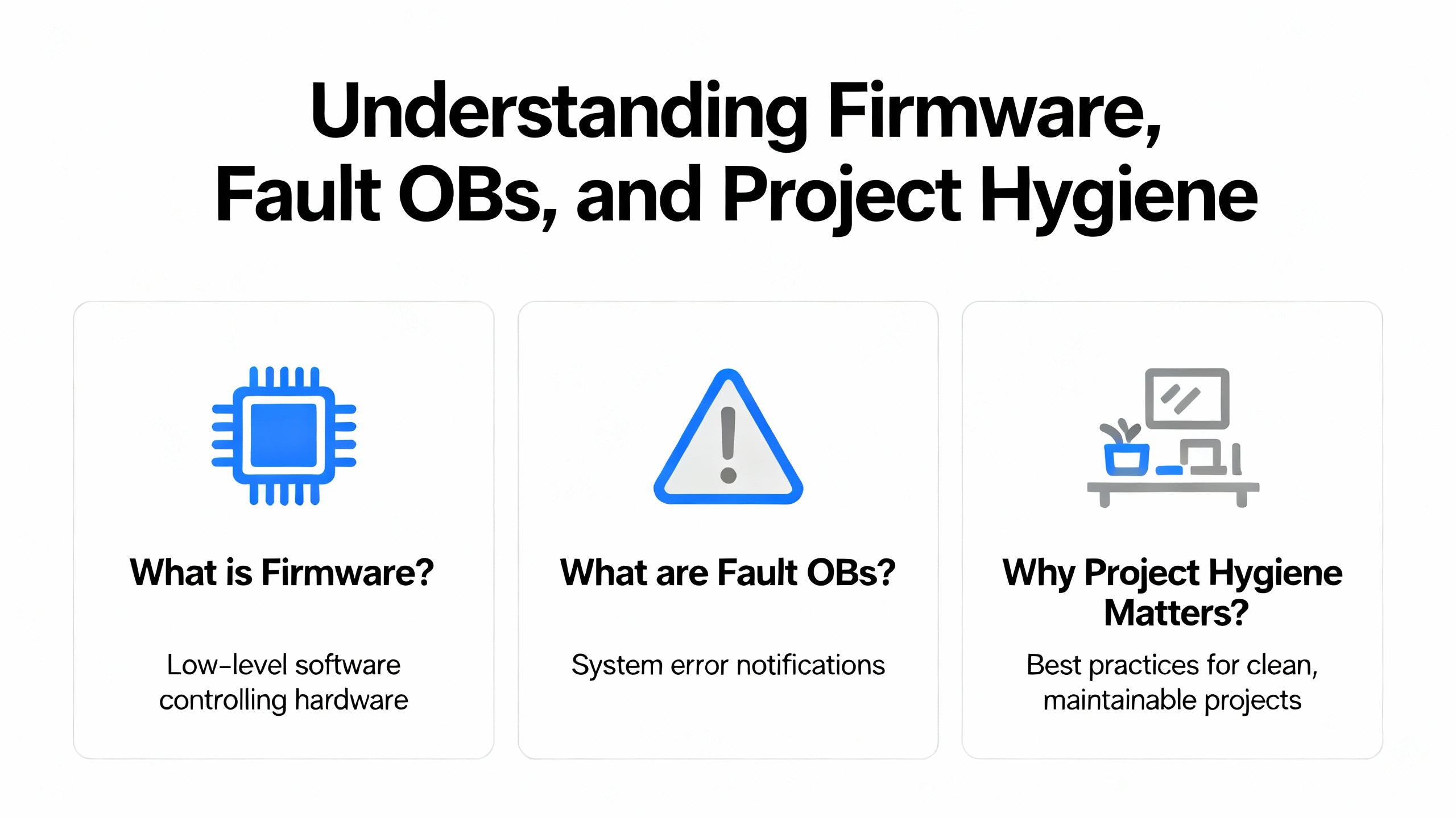
Firmware, Fault OBs, and Project Hygiene
A robust CPU project includes the right fault organization blocks so your system records and handles problems predictably. Practitioners regularly recommend enabling OBs that record hardware and rack faults as well as programming errors so the PLC does not dive into STOP without leaving a trail. Mismatches between project firmware targets and installed device firmware can stop a CPU from entering RUN. Align TIA Portal targets with installed versions or schedule a firmware update. Siemens offers time-limited trials of engineering tools, which can be useful in a pinch when you need to connect and read diagnostics without delay.
Tools, Cables, and Practical Purchasing Choices
Programming and diagnostics cables matter. Teams often carry the Siemens USB MPI/Profibus adapter, but many have also used a cost-effective third-party MPI/Profibus USB adapter from vendors like PLCCable. Reports indicate that certain third-party USB adapters are not appropriate for Profibus networks above 1.5 Mbit, so match your tool to your bus speed. When direct USB access to a PLC is constrained, field teams have used a nearby modem module with a standard USB printer cable to reach diagnostics, a pragmatic workaround shared by experienced technicians. Stocking spare Profibus connectors is inexpensive and shortens recovery time; replace suspect connectors rather than arguing with them.
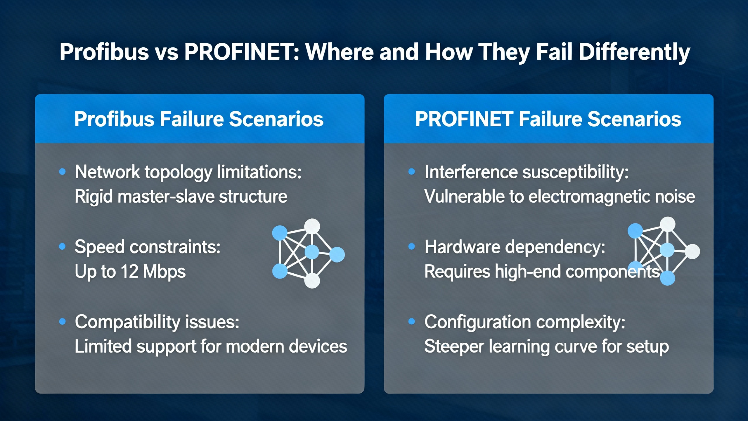
Profibus vs PROFINET: Where and How They Fail Differently
Profibus problems tend to be very physical. Termination in the wrong place, a kinked cable, or a mid-run connector that got re-terminated by someone in a hurry will produce immediate and repeatable BF symptoms, often at the far end of the cable run. The master may flash BF while some nodes appear healthy because only the chain beyond the misconfiguration is affected. PROFINET’s failures can be more systemic and sometimes misleading. Loops, VLAN oddities, and DPI firewalls can sink application sessions without ever disturbing basic connectivity checks. The fix on Ethernet is as much about clean topology and security policy as it is about connector integrity.
Calibrations and Special Cases You Should Not Overlook
Occasionally, a complaint that looks like a CPU or I/O fault traces to a module being between states due to a calibration step. Siemens documentation for ET 200SP analog modules explains that the final step of user calibration requires explicit confirmation. The module expects a job data set with the correct step flag and a timestamp in a specific format, and it will report mode and status when the calibration concludes successfully. If an error occurs at that last step, the module discards new calibration values and keeps the old ones. This is not a day-to-day scenario in most CPU fault hunts, but when a channel appears stuck or inconsistent after maintenance, checking whether a calibration procedure properly completed is surprisingly effective.

A Field-Proven Troubleshooting Flow
If you walked into my shop with a dead network or a CPU that refuses to stay in RUN, we would follow a concise flow. The first step is safety: secure the machine state and ensure outputs cannot energize unexpectedly. The second step is visibility: read and save the Diagnostic Buffer and gather LED states with timestamps. The third step is fundamentals: verify power quality, grounding, and obvious connector defects. The fourth step is isolation: on Profibus, test the end-of-line terminations and execute the IM swap technique; on Ethernet, eliminate complex network paths to see if a direct link stabilizes communications. The fifth step is alignment: confirm project configuration, device part numbers and hardware revisions, addressing schemes, and firmware compatibility. The sixth step is escalation: use a dedicated Profibus analyzer or managed switch telemetry to locate stubborn line-quality issues. At each step, document what changed, what you measured, and what the PLC said in return. When the trail ends, you have a case file that accelerates vendor support and avoids repeating the same rabbit holes.
Case Nuggets That Keep Teams Honest
A site with a CPU 315-2DP ran for years before a power module failure precipitated communications issues—a reminder that “it worked last year” is not a diagnostic. Another team restored a dead Profibus segment by replacing a single connector and a short cable to a field cabinet, proving that “one bad crimp” can take down the whole line. Elsewhere, a plant reduced Profibus speed from the usual 1.5 Mbaud to a lower rate to overcome marginal line quality while planning a permanent re-cabling. On the Ethernet side, a system with successful pings and TCP opens still failed at the application layer until the team excluded a DPI firewall from inspecting S7 sessions. In several cases, a simple CPU STOP-to-RUN transition cleared hung sockets that diagnostics alone had not surfaced. None of these are outliers; they are ordinary outcomes when teams keep their heads, trust the buffer, and fix the root cause rather than symptoms.
Documentation Discipline and Spares Strategy
Reducing mean time to repair is more about preparation than heroics. Keep an up-to-date network sketch with node addresses, cable paths, terminator positions, bus speed, and segment lengths. Record part numbers and hardware revisions for every module, and keep a small stock of known-good connectors, short patch segments, and at least one spare interface module for critical stations. Use TIA Portal to export and archive Diagnostic Buffers from significant incidents so that patterns are visible across months, not hours. Train operators to capture LED states before power cycling, and give maintenance a simple playbook for power, termination, addressing, and connector checks they can complete while you are en route.
Short FAQ
Q: The master’s BF is solid red, yet some devices appear fine. Where do I start? A: Start near the master and verify termination states, then walk the segment to the first node where BF appears. A mis-set terminator at a mid-run node or a single bad connector will often cause every downstream node to fail while upstream nodes remain happy. The Oxmaint community describes exactly this failure pattern.
Q: How do I distinguish a cabling fault from a bad remote interface module? A: Use the IM swap isolation test. Move the suspect IM into a known-good cabinet without changing DIP switches, power it, and connect it as if it were local. If the CPU detects the IM but flags missing I/O, your path is good and the issue is likely in the remote cabinet’s cabling or connector. If the CPU still does not see the IM, you likely have a failing module or an addressing mismatch.
Q: Are third‑party USB MPI/Profibus adapters acceptable in production? A: Many teams use them successfully. Be aware of bus-speed limits; some adapter models are not suitable above about 1.5 Mbit. If your site runs at typical Profibus speeds near that value, confirm the adapter’s spec with your maintenance standards.
Closing
Diagnosing Siemens CPU module faults is a craft made of calm habits and clear evidence. Read the buffer, trust the physics, isolate relentlessly, and document what you learn. If you want a partner who treats your plant like their own and gets you from alarm to answer without drama, that’s the work I do every day.
References
- https://www.utdallas.edu/~ewong/SE6367/01-Project/08-SFL-papers/04-BP.pdf
- https://minds.wisconsin.edu/bitstream/handle/1793/91986/Jin_uwm_0263m_12430.pdf?sequence=1&isAllowed=y
- https://www.plctalk.net/forums/threads/siemens-cpu-315-2dp-troubleshooting.138977/
- https://synchronics.co.in/common-siemens-s7-plc-fault-codes-fixes/
- https://www.justanswer.com/electronics/nwunu-siemens-s7-1500-cpu-when-powered-display.html
- https://www.linkedin.com/posts/kyle-li-489a45257_plc-industrialautomation-siemens-activity-7312379759592620032-VUso
- https://community.oxmaint.com/discussion-forum/troubleshooting-siemens-cpu-315-2dp-plc-communication-and-power-module-faults
- https://plcvfd.com/understanding-sf-and-bf-in-siemens-plcs-diagnostic-tips-and-solutions/
- https://forum.inductiveautomation.com/t/siemens-s7-300-connection-errors/27716
- https://industrialautomationco.com/blogs/news/comprehensive-guide-to-error-codes-in-the-simatic-s7-1200?srsltid=AfmBOor7YkfMaCCX7u1JU2NgQ4IG94LSjcolD578TU0k_yohbYOajTwY
Keep your system in play!
Top Media Coverage
Categories


Related articles Browse All
-
 amikong NewsSchneider Electric HMIGTO5310: A Powerful Touchscreen Panel for Industrial Automation2025-08-11 16:24:25Overview of the Schneider Electric HMIGTO5310 The Schneider Electric HMIGTO5310 is a high-performance Magelis GTO touchscreen panel designed for industrial automation and infrastructure applications. With a 10.4" TFT LCD display and 640 x 480 VGA resolution, this HMI delivers crisp, clear visu...
 -
 BlogImplementing Vision Systems for Industrial Robots: Enhancing Precision and Automation2025-08-12 11:26:54Industrial robots gain powerful new abilities through vision systems. These systems give robots the sense of sight, so they can understand and react to what is around them. So, robots can perform complex tasks with greater accuracy and flexibility. Automation in manufacturing reaches a new level of ...
 -
 BlogOptimizing PM Schedules Data-Driven Approaches to Preventative Maintenance2025-08-21 18:08:33Moving away from fixed maintenance schedules is a significant operational shift. Companies now use data to guide their maintenance efforts. This change leads to greater efficiency and equipment reliability. The goal is to perform the right task at the right time, based on real information, not just ...


- Q&A
- Policies How to order Part status information Shipping Method Return Policy Warranty Policy Payment Terms
- Asset Recovery
- We Buy Your Equipment. Industry Cases Amikong News Technical Resources Why choose us
- ADDRESS
-
 32D UNITS,GUOMAO BUILDING,NO 388 HUBIN SOUTH ROAD,SIMING DISTRICT,XIAMEN
Leave Your Comment