
-
Please try to be as accurate as possible with your search.
-
We can quote you on 1000s of specialist parts, even if they are not listed on our website.
-
We can't find any results for “”.
Emergency VFD Repair Parts: Urgent Variable Frequency Drive Solutions
When a line stops at 2:00 AM, your variable frequency drive is often the first suspect and the fastest path back to production. I’ve spent nights with fans roaring, panels open, and maintenance teams waiting on a single part to arrive. The pattern is consistent: a good triage, a small set of high‑impact replacement parts, and disciplined power‑quality mitigation turn a crisis into a controlled recovery. This article distills that field experience with vendor‑neutral guidance and cross‑checks from established sources such as Fluke, EPRI, NEMA guidance cited by Joliet Technologies, ADM Engineering Inc., Control Engineering, and multiple repair houses reporting turnaround and savings.
What “Emergency” Means in a VFD Failure
A VFD fault rarely fails in isolation; it’s a system problem involving incoming power, the drive’s DC bus and switching stage, the motor and load, and the environment. The job in an emergency is simple to describe and difficult to execute quickly: read the clues the drive gives you, verify power is healthy, stabilize the environment, and swap the part that restores safe control the fastest. That is why the parts you choose to stock matter more than ever—some components are common failure points and others are powerful stabilizers that buy you diagnostic time.
A variable frequency drive controls AC motor speed and torque by modulating output frequency and voltage. The benefits are well known—smoother starts, energy savings, and better process control—but those same power‑electronics that deliver the benefits are sensitive to heat, contamination, poor connections, and disturbances. The result is well documented by Control Engineering and Global Electronic Services: a clean, cool, well‑grounded, and well‑programmed installation runs for years; neglect shortens service life and drives urgent calls.
The First Hour: Triage That Drives Parts Decisions
Start with the drive’s own fault information. Modern drives display fault text or codes that classify an electrical, thermal, mechanical, or control problem. Emotron’s seven‑step troubleshooting guidance aligns with what works in the field: read the code, inspect power and connections, find the root cause rather than clearing symptoms, check environment and cooling, inspect the motor and load, then reset and watch. That sequence keeps you from wasting time chasing the wrong part.
While the panel is open, measure the input and the DC bus. Fluke’s guidance is straightforward: confirm balanced line‑to‑line voltages with a true‑RMS meter and then verify the DC bus sits near the expected rectified level. For a 480 VAC class drive, the DC bus typically reads a little over about 678 VDC; a reading that is substantially low or badly unstable points you toward upstream power quality or internal capacitor health. Do not use an averaging meter on a VFD output; Fluke warns such meters can be off by about 40% on non‑sinusoidal waveforms, which leads to wrong conclusions and unnecessary part swaps.
Next, verify the environment. Overtemperature faults track closely with dust‑clogged heat sinks or fans, restricted airflow, and high ambient conditions. Many drive makers and Canroon note 104°F as a common upper bound for full‑capacity operation; pushing higher accelerates degradation. If your enclosure is a simple vented style, expect to clean more often than a sealed design. The PCTX maintenance guidance and the Do Supply troubleshooting notes are aligned here: keep the space clean and dry, use NEMA 12 or better in dusty or corrosive areas, and prevent condensation.
Finally, consider the motor and load. Overcurrent during acceleration often signals mechanical binding or a process that changed since the last run. Both HARS and Do Supply emphasize that fan and pump power demand rises rapidly with speed; a modest speed increase can drive a large jump in current. Slowing the acceleration ramp or temporarily unloading conveyors reduces stress into the drive and buys diagnostic time. If the motor insulation is questionable, a megohmmeter reading by qualified personnel prevents blowing a freshly repaired VFD on restart.
The Parts That Get You Running: High‑Yield Spares
Certain components fail more often and restore function quickly when swapped. From the maintenance records and vendor briefs, cooling fans and DC bus capacitors are at the top of the list. PCTX recommends replacing main bus capacitors roughly every seven years and cooling fans every three to five years; experience bears out that fans often fail silently first, and ripple or DC bus instability follows as capacitors age, especially in high heat. Having both on the shelf means you can stabilize thermals and DC storage quickly.
Fuses and upstream breakers are another fast win. A blown line fuse points you toward a short or a surge event; replacing it without addressing the cause may be a short reprieve, but in an emergency it restores power for further diagnosis. MOV surge suppressors on the input can burn under repeated surges; UpFix cites a case where a burnt MOV plus firmware issues were resolved in a few days, a reminder that transient protection is both a consumable and a diagnostic clue.
If the drive trips with overvoltage during deceleration or when the load overhauls the motor, have a braking resistor on hand. Both HARS and Do Supply describe this scenario and the remedies: increase decel time or add a dynamic braking element. In plants with common decel events, a braking resistor is an inexpensive stabilizer that saves you from repeated nuisance trips.
Power quality hardware deserves a place in your emergency kit as much as replacement boards. Maxivolt and EPRI research show that coordinating a line reactor with a properly sized surge protective device improves ride‑through during transients. DC link chokes and smoothing capacitors reduce ripple on the DC rail; AC line reactors limit current spikes and harmonic content, though they also introduce voltage drop that can trigger undervoltage trips on weak upstream feeders. The coordination matters; an SPD sized to the system and placed at the drive input clamps spikes that a reactor alone cannot fix, while the reactor tames current quality the SPD will never touch.

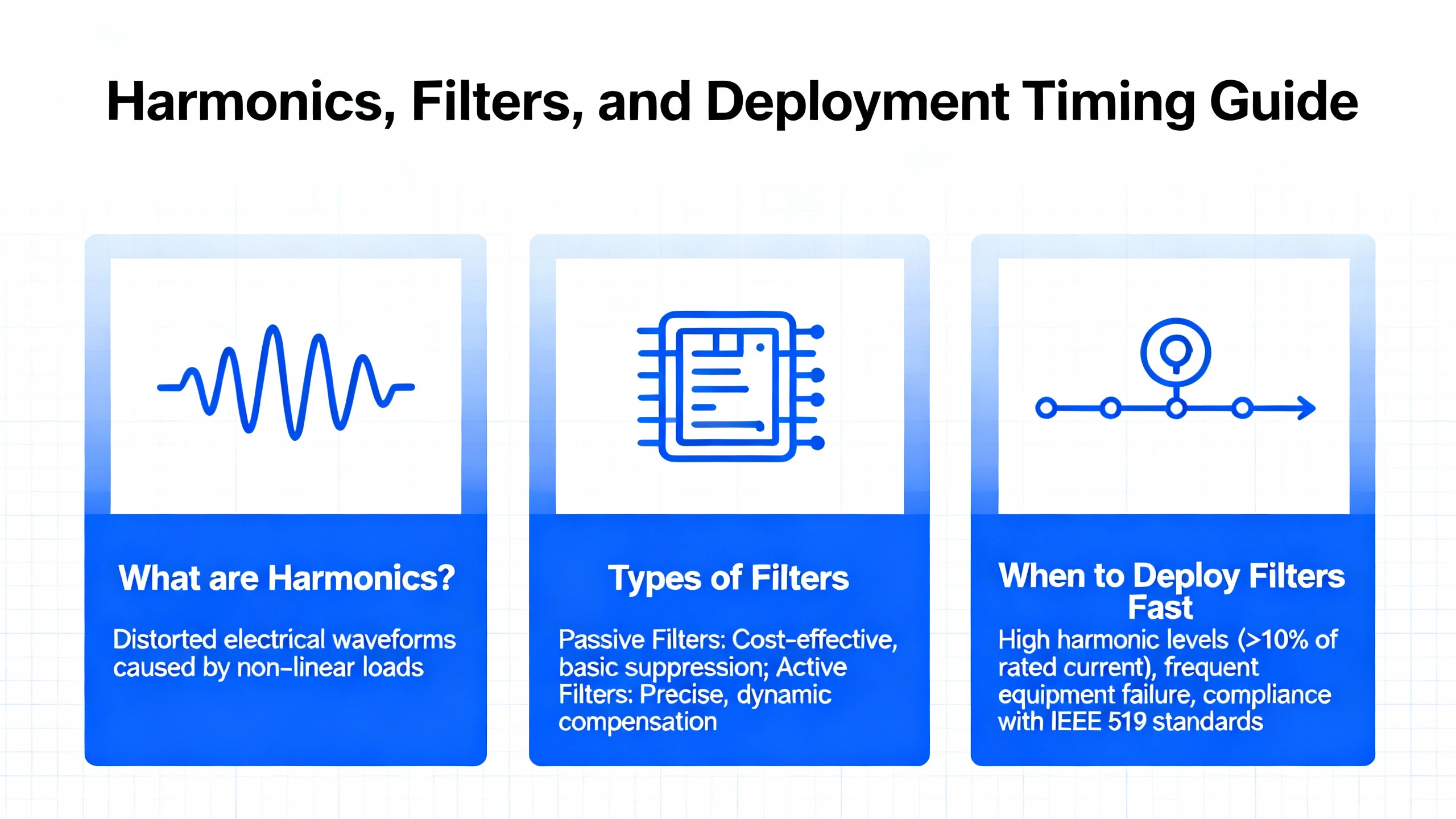
Harmonics, Filters, and When to Deploy Them Fast
Harmonics are a chronic issue in VFD sites and sometimes the acute cause of your overnight fault. ADM Engineering Inc. summarizes the practical options. Passive harmonic filters use a tuned inductor‑capacitor network in parallel with the drive; they are cost‑effective when the harmonic profile is well known and the goal is to shunt specific bands. Above their tuning point, they behave like inductors; below, they act like capacitors that also help power factor. Active harmonic filters measure distortion across a range with current transformers and a controller, then inject an equal‑magnitude, opposite‑phase current through IGBTs to cancel across multiple orders. They are more expensive but solve variable profiles in light and medium‑voltage contexts. If your emergency is tied to periodic trips in a mixed‑load panel, installing an active filter can be the shortest route to stability while you plan a permanent fix.
The table below summarizes how these parts stabilize your system quickly.
| Device or Part | Purpose in an Emergency | Strengths | Watch‑outs |
|---|---|---|---|
| Cooling fans | Restore airflow and reduce drive temperature | Cheap, fast to replace, common failure | Does not fix root thermal load or blocked ducts |
| DC bus capacitors | Reduce ripple, stabilize DC bus voltage | Addresses aging failure, improves ride‑through | Requires safe discharge and qualified work |
| Fuses/breakers | Restore input power after fault isolation | Immediate restoration for diagnosis | Blown again if short or surge not resolved |
| MOV/SPD | Clamp input transients | Critical with reactors for ride‑through per EPRI | Size correctly; coordinate with upstream protection |
| AC line reactor | Add impedance, limit current spikes/harmonics | Improves current quality | Drops voltage; may induce undervoltage trips |
| DC link choke | Reduce DC bus ripple current | Eases stress on capacitors | Adds losses; must be sized to bus rating |
| Braking resistor | Absorb regenerative energy on decel | Prevents decel overvoltage trips | Thermal management; ensure correct ohmic value |
| Passive harmonic filter | Shunt tuned harmonics and aid PF | Cost‑effective when spectrum is known | Mis‑tuning reduces effectiveness; adds components |
| Active harmonic filter | Cancel variable harmonics adaptively | Broad mitigation; fast stabilization | Higher cost; commissioning required |
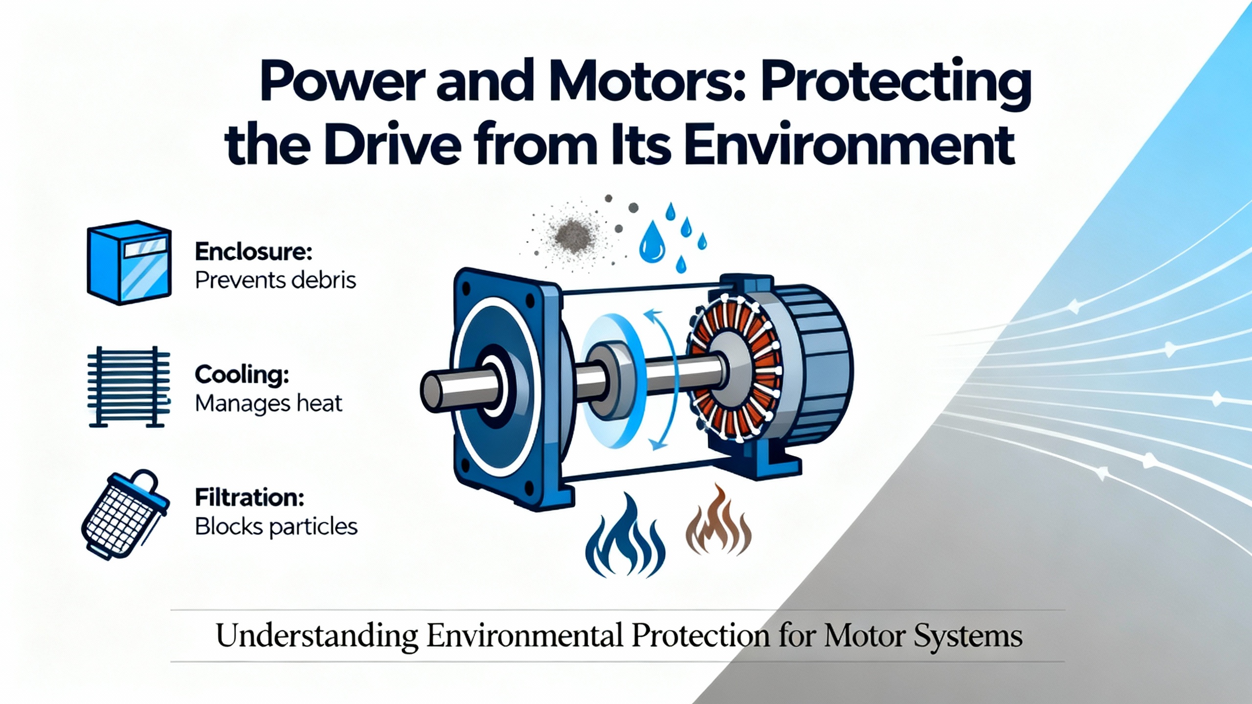
Power and Motors: Protecting the Drive from Its Environment
If your failure mode shows up as persistent overvoltage at the motor terminals, reflected wave spikes and long lead lengths might be part of the story. Joliet Technologies points to NEMA MG 1 Parts 30 and 31 for VFD‑rated motors and notes that PWM drives can create two to four times the line‑voltage spikes at motor terminals. If your installation includes long output runs, add output filtering or use motors rated for inverter duty to avoid insulation stress. When temperatures run high, every degree above the rated ambient takes a measurable bite out of component life; Canroon’s guidance on thermal and humidity controls reinforces that keeping the enclosure at or below about 104°F and controlling moisture is not just good practice but a life‑extension tactic.
Electrical noise and grounding problems show up as erratic behavior and false trips. Vocal Media’s troubleshooting overview points to proper grounding, shielded motor cables with correct terminations, and reducing switching frequency to reduce EMI. When input power is unstable, use surge protectors and line reactors in combination; Maxivolt and EPRI describe how pairing devices results in better overall immunity than either device alone.
Fast, Reliable Measurements That Decide the Next Part
In an emergency, instrumentation accuracy matters. Fluke recommends starting with a true‑RMS meter to verify balanced line voltage and an in‑range DC bus; that single step separates upstream power issues from internal failures. If your meter shows the DC bus roughly twenty percent below nominal and nothing else explains it, expect capacitor health or excessive ripple. When readings don’t match behavior, move to an oscilloscope to see high‑frequency noise and transient spikes that average numbers hide. For motor health and wiring faults, Emotron’s toolkit of a megohmmeter and clamp meter helps confirm insulation integrity, phase balance, and abnormal current draw; a thermal camera quickly highlights hot spots on bus bars, terminals, and heat sinks.
The quick reference below translates those measurements into immediate, parts‑oriented actions.
| Check | What to Look For | Likely Cause | Part or Action |
|---|---|---|---|
| L1‑L2, L2‑L3, L3‑L1 equal and within spec | Balanced voltages | Healthy feed | Proceed to DC bus check |
| DC bus near expected rectified level | Stable VDC (e.g., about 678 VDC for 480 VAC class) | Rectifier and caps OK | Move downstream; check motor/load |
| DC bus low or unstable | Significant ripple or depressed VDC | Aged capacitors, input sag | Replace bus capacitors, add line reactor or DC choke, check SPD |
| Overvoltage on decel | Fault during rapid stop | Regeneration without path | Install or verify braking resistor; lengthen decel |
| Overcurrent on accel | Trip during ramp | Mechanical binding or too steep ramp | Reduce acceleration ramp; inspect load; check motor current with clamp meter |
| Erratic speed or false faults | EMI or poor grounding | Unshielded or mis‑terminated cables | Correct shields, improve grounding, consider output filter |

Repair Versus Replace Under Time Pressure
Fast, expert repair is often the cheapest path back to throughput. UpFix reports typical turnarounds of two to five business days and claims cost savings up to eighty percent versus buying new; in my experience those numbers are plausible for mainstream brands and sizes when the fault is on the board level and spares are in stock. Some providers like Global Electronic Services underscore that even well‑maintained drives eventually reach end of life; that reality means you should weigh the repair with a realistic view of age, the environment, and how critical harmonics or power problems are in your plant. In an emergency, your decision criteria are straightforward: if repair brings you back within your acceptable downtime window and the vendor warranties the work, proceed; if firmware, obsolescence, or catastrophic damage prevents a reliable fix, stage a pre‑parameterized replacement drive to minimize commissioning time.
Stocking Strategy: What Belongs in Your VFD Emergency Kit
The best emergency kit blends consumables, common failure items, and power‑quality stabilizers rather than a single spare drive for every size. Make room for cooling fans and DC bus capacitors matched to your fleet’s key frame sizes so you can restore airflow and DC stability immediately. Add input fuses and a few correctly rated SPDs for your common voltages; when a surge event hits multiple panels, you will run out of this category first. Keep at least one braking resistor capable of handling your largest deceleration duty, especially in conveyor and hoist areas. Include an AC line reactor and a DC link choke sized for a representative midrange drive; a quick add at the panel can turn noisy power into acceptable power long enough to run a shift. If harmonics are a recurring pain, pre‑select a passive filter tuned for your worst offender or stage an active filter sized to the bus. Round out the kit with the instruments that pay for themselves in minutes: a true‑RMS DMM, a clamp meter, a megohmmeter, and a thermal camera.
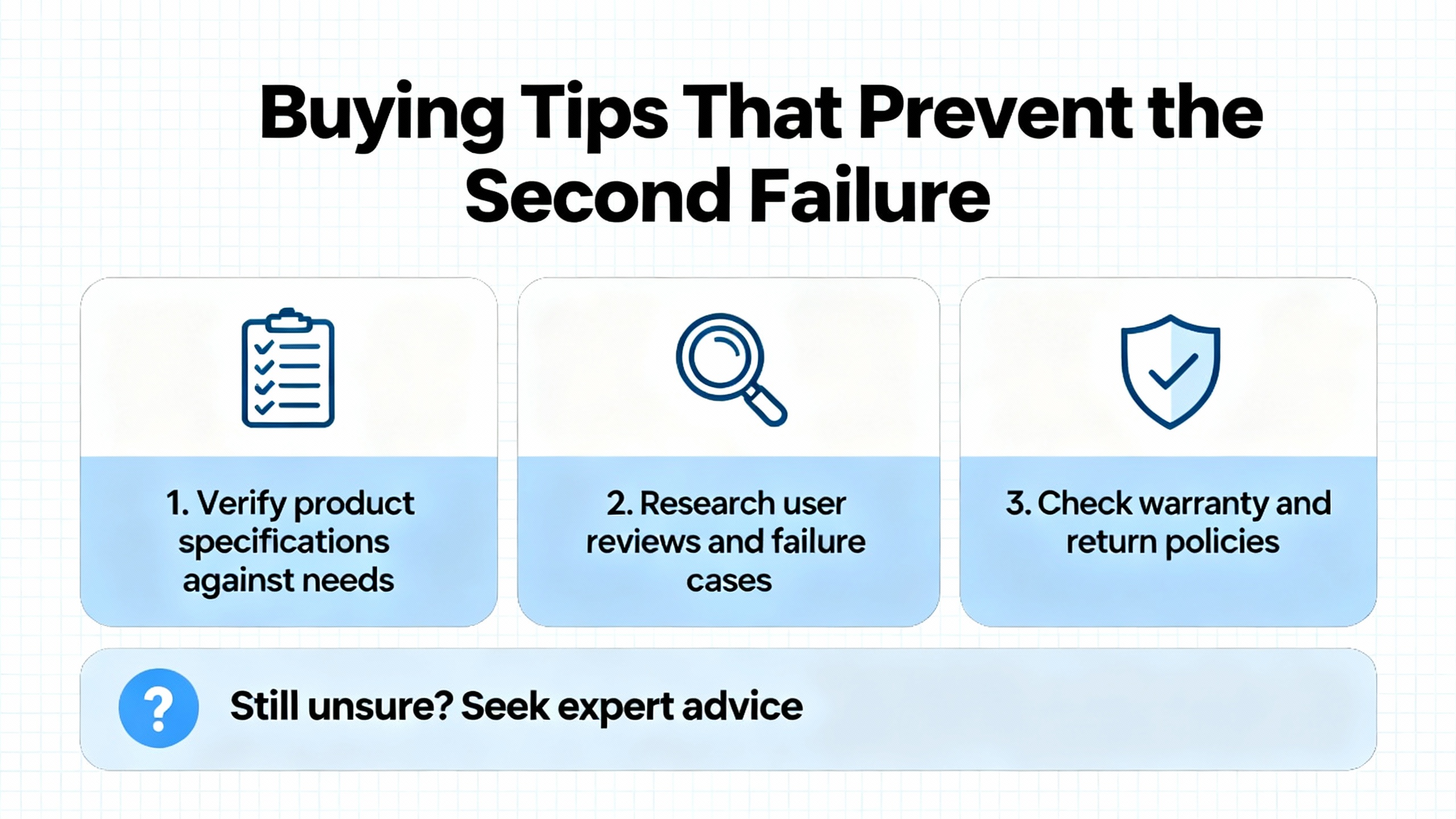
Buying Tips That Prevent the Second Failure
Match parts to actual drive ratings and application duty, not just horsepower. Drives carry different current ratings for normal duty and heavy duty; Joliet Technologies reminds that heavy‑duty ratings are lower and align with constant‑torque loads. For motors exposed to fast PWM edges and long leads, use VFD‑rated motors per NEMA MG 1 Parts 30 and 31 or add output filtering to protect insulation. When selecting SPDs, size to the system’s tolerance and coordinate with upstream protection so clamping levels make sense; place them at the drive input to protect the front end. Be deliberate with line reactors; added impedance improves current quality but drops voltage, which can trigger undervoltage trips where incoming voltage is already at the low edge. For harmonic filters, choose passive options where your spectrum is known and relatively stable; choose active when your load diversity changes across shifts or seasons. Finally, consider the provider’s repair discipline. UpFix cites IPC‑certified repairs, warranty options, and large customer savings; while marketing claims vary, a shop that documents root cause, replaces life‑limited components such as capacitors and fans proactively, and burns in the unit under load saves you repeat trips.
Care After the Crisis: Lock in Stability
Once production is back, close the loop on root causes. Dust and heat drive a large share of failures; Control Engineering and Canroon emphasize keeping heat sinks, fans, and enclosures clean, maintaining airflow, and preventing moisture ingress. PCTX’s schedule of daily noise and environment checks, monthly filter service, and annual torque checks and deep cleaning is a pragmatic pattern that applies across brands. Track firmware versions and apply updates deliberately; UpFix and Fluke both point to practical diagnostics that only help when your device is current and stable. Use the drive’s logs to trend current, frequency, and trips. A quick oscilloscope check of the DC bus ripple annually under a representative load tells you if capacitors are aging out before they surprise you. Document every emergency with fault codes, observed causes, and parts used; that history guides what you stock and which vendors earn repeat work.
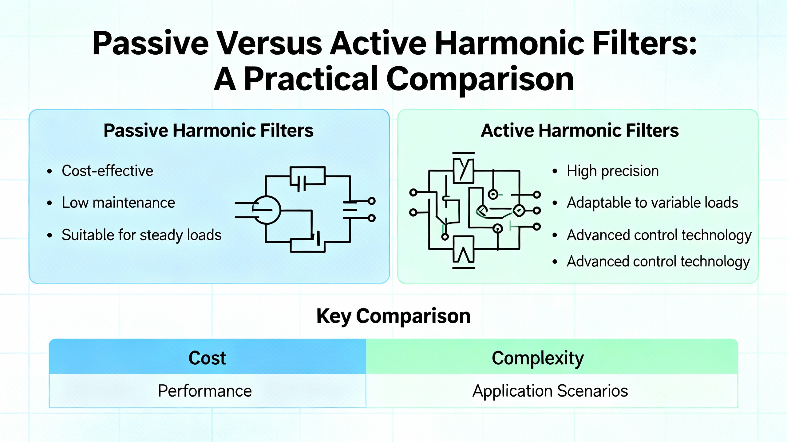
Passive Versus Active Harmonic Filters: A Practical Comparison
Harmonics do not only waste energy; they pile on heating and nuisance faults that look like random gremlins until you correlate trips with production patterns. ADM Engineering Inc. highlights how passive filters, built from tuned inductors and capacitors, efficiently shunt specific harmonic orders when you know the spectrum and want a cost‑effective fix. Active filters measure and inject opposite‑phase currents across multiple orders, which suits variable and mixed loads in light and medium‑voltage systems. The buying choice is pragmatic: go passive when your problem is narrow and stable; go active when it moves around with process changeovers and shift mixes. Align your goals with IEEE 519 guidelines cited by multiple troubleshooting sources to avoid solving your VFD trip only to move the problem to your transformers.
| Filter Type | Best Use Case | Advantages | Considerations |
|---|---|---|---|
| Passive harmonic filter | Known harmonic spectrum and cost sensitivity | Lower cost, simple, improves power factor below tuning | Needs correct tuning; limited coverage outside target bands |
| Active harmonic filter | Mixed or changing load profiles | Broad mitigation across orders; adaptive | Higher cost; requires commissioning and space |
Frequently Asked Questions
What are the first electrical checks I should do when a VFD trips?
Start with the display codes to classify the fault. Measure input line‑to‑line voltages with a true‑RMS meter to confirm balance and magnitude, then measure the DC bus to see if it sits near the expected rectified value. If the DC bus is notably low or unstable, examine capacitors and incoming power quality. If the DC bus is healthy, shift attention to the motor and mechanical load.
Which spare parts give me the fastest path back to production?
Cooling fans, DC bus capacitors, fuses, and an input SPD solve a significant share of urgent failures. When overvoltage trips happen during deceleration, a braking resistor clears the issue immediately. In noisy or marginal power scenarios, a line reactor or DC choke stabilizes current while you plan a permanent fix.
How do I decide between repairing a drive and replacing it during a breakdown?
Balance downtime, age, and the fault type. Board‑level failures on mainstream models are often repaired in a few business days with significant cost savings, as reported by UpFix. Obsolete hardware, heavy environmental damage, or firmware issues that block reliable operation favor replacement. Keeping a pre‑parameterized spare for your most critical size shortens replacement time drastically.
Will a line reactor always help my VFD ride through disturbances?
It helps with current quality but it also drops voltage. In plants with already low supply margins or frequent sags, that drop can trigger undervoltage faults. Pair the reactor with a correctly sized SPD at the input as EPRI research cited by Maxivolt suggests, and verify the resulting voltage stays within the drive’s tolerance under load.
When should I invest in a harmonic filter rather than just a reactor?
A reactor reduces current distortion but does not target specific harmonic orders. If nuisance trips correlate with other drives running, or if transformer and upstream equipment run hot due to distortion, a filter is the right tool. Choose a passive filter when you know your harmonic profile and an active filter when the spectrum changes with production.
What instrumentation should be part of my emergency kit?
Carry a true‑RMS digital multimeter, a clamp meter, a megohmmeter for insulation checks, and a thermal camera. The DMM and clamp meter resolve most power questions quickly, the megohmmeter verifies motor health before energizing, and the thermal camera reveals hot spots that point straight to loose connections, blocked airflow, or overloaded components.
Key Takeaway
Emergency VFD work is won or lost on preparation. Stock the parts that fail most and the devices that stabilize power. Verify the electrical basics with instruments you trust. Use passive and active filtering deliberately to eliminate harmonic‑driven instability. When you choose between repair and replacement, pick the path that meets your downtime window without creating a new risk. The evidence across Fluke’s test guidance, EPRI’s ride‑through findings, NEMA’s motor standards summarized by Joliet Technologies, and the maintenance playbooks from PCTX, Control Engineering, and others points to the same simple truth: clean power, cool electronics, correct parameters, and a small set of well‑chosen parts will turn your next 2:00 AM call into a short interruption rather than a long outage.
References
Fluke; EPRI; NEMA guidance summarized by Joliet Technologies; ADM Engineering Inc.; Control Engineering; PCTX; Do Supply; HARS; Maxivolt; Vocal Media; Emotron; UpFix; Franklin Electric; Global Electronic Services.
- https://wce.macomb.edu/index.cfm?method=course.classinformation&coursenumber=CMNF-8282
- https://do-server1.sfs.uwm.edu/mirror/$25B3X74842/chap/35B8X54/variable+frequency+drive+design+guide+abhisam.pdf
- https://admeng.com/troubleshooting-issues-caused-by-vfd.html
- https://www.hars-vfd.com/basic-troubleshooting-methods-for-variable-frequency-drives-vfds.html
- https://blog.upfix.com/how-to-troubleshoot-a-faulty-variable-frequency-drive-vfd
- https://www.canroon.com/Industry-Insights/How-to-Avoid-Common-Frequency-Regulation-Failures-in-VFDs
- https://www.controleng.com/10-essential-maintenance-and-troubleshooting-tips-for-vfds/
- https://www.csemag.com/10-essential-maintenance-and-troubleshooting-tips-for-vfds/
- https://gesrepair.com/why-your-industrial-vfds-are-failing-and-how-to-prevent-it/
- https://pctx.us/variable-frequency-drive-maintenance/
Keep your system in play!
Top Media Coverage
Categories


Related articles Browse All
-
 amikong NewsSchneider Electric HMIGTO5310: A Powerful Touchscreen Panel for Industrial Automation2025-08-11 16:24:25Overview of the Schneider Electric HMIGTO5310 The Schneider Electric HMIGTO5310 is a high-performance Magelis GTO touchscreen panel designed for industrial automation and infrastructure applications. With a 10.4" TFT LCD display and 640 x 480 VGA resolution, this HMI delivers crisp, clear visu...
 -
 BlogImplementing Vision Systems for Industrial Robots: Enhancing Precision and Automation2025-08-12 11:26:54Industrial robots gain powerful new abilities through vision systems. These systems give robots the sense of sight, so they can understand and react to what is around them. So, robots can perform complex tasks with greater accuracy and flexibility. Automation in manufacturing reaches a new level of ...
 -
 BlogOptimizing PM Schedules Data-Driven Approaches to Preventative Maintenance2025-08-21 18:08:33Moving away from fixed maintenance schedules is a significant operational shift. Companies now use data to guide their maintenance efforts. This change leads to greater efficiency and equipment reliability. The goal is to perform the right task at the right time, based on real information, not just ...


- Q&A
- Policies How to order Part status information Shipping Method Return Policy Warranty Policy Payment Terms
- Asset Recovery
- We Buy Your Equipment. Industry Cases Amikong News Technical Resources Why choose us
- Registered Address
-
32D Guomao Building, No.388, Hubin south Road, Siming district, Xiamen,Fujian, China

Leave Your Comment