
-
Please try to be as accurate as possible with your search.
-
We can quote you on 1000s of specialist parts, even if they are not listed on our website.
-
We can't find any results for “”.
Flow Meter Signal Loss Troubleshooting: A Diagnostic Approach
When a flow meter goes silent or its signal starts dropping out, the plant does not just lose a number on a screen. It loses control over dosing, safety margins, and product quality. In concrete batching, for example, poor water flow measurement directly affects strength and durability, as highlighted by IPEC. Sierra Instruments points out that across oil and gas, manufacturing, and utilities, inaccurate or missing flow data drives downtime, higher energy use, and compliance risk. As a systems integrator, I have learned that the difference between a quick fix and days of trial and error is a disciplined diagnostic approach, not guesswork and parts swapping.
This article walks through a practical, field-tested way to troubleshoot flow meter signal loss. The goal is not to turn you into a specialist on every meter technology but to give you a consistent method that respects how the instruments actually fail in the real world, backed by manufacturer and industry guidance.
Why Signal Loss Is More Than an Instrument Problem
Signal loss is often treated as a purely instrument issue, but the research and field experience say otherwise. Holykell notes that more than ninety percent of flow measurement issues start with incorrect selection and application, before the meter even sees fluid. Turbines Incorporated, Sierra Instruments, and multiple manufacturers emphasize installation quality, fluid conditions, and environment as dominant contributors to failure and drift.
In water systems, IPEC has shown that poor meter performance does not just affect one reading; it cascades into bad batching, increased material waste, and higher carbon emissions. In harsh services, Sierra Instruments describes how fouling, wear, and poor calibration practice change a small measurement error into a chronic production problem. Signal loss in that context is the visible part of a larger reliability issue.
A good troubleshooting approach therefore starts wide: power, wiring, process conditions, and meter selection all get considered before you condemn the instrument.
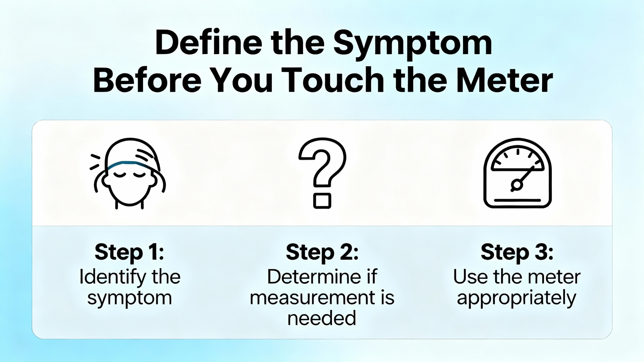
Define the Symptom Before You Touch the Meter
Before you grab a meter or laptop, it is important to define exactly what “signal loss” looks like in your system. Manufacturers and practitioners repeatedly make the same point: you cannot diagnose what you have not described.
Many sources, from GAIMC to BJSSAE and Manas, differentiate between a total loss of output, a zero reading, intermittent dropouts, and unstable or wildly fluctuating signals. A flow meter that reads exact zero when you can see flow in a sight glass, as IPEC notes, suggests issues like broken signal cables, faulty pulse transmitters, or damaged internal measuring elements. GAIMC and BJSSAE describe apparent signal loss when power is still present but outputs are misconfigured, wiring is reversed, or sensors are damaged.
On the control.com forum, experienced troubleshooters stress the importance of context. They ask whether the problem affects a single transmitter or multiple ones on the same power supply or cable tray, whether the problem started after a shutdown, configuration change, or mechanical modification, and whether the symptom is continuous, periodic, or weather related. That basic history often separates a systemic power or grounding problem from a localized sensor failure.
In practice, I recommend capturing four things before you start: what the operator believes is wrong, how the signal behaves over time, what changed in the plant recently, and which other instruments share the same power, cabling, or process line.
Step 1 – Prove the Electrical and Signal Chain
Most structured troubleshooting guides, from GAIMC and Microsensor to Primary Flow Signal and the control.com experts, begin with power and signal integrity. The reasoning is simple: if the meter and loop are not electrically sound, no amount of mechanical or process checking will recover a stable signal.
Verify Power and Basic Health
GAIMC and Microsensor document many “dead” or blank meters that turned out to be power problems rather than sensor failures. Common issues include using multiple power types at once, miswiring 24 V and 220 V to the wrong terminals, loose internal connectors from transport, and undersized power modules that cannot supply enough current. Manas and BJSSAE also emphasize basic checks for blown fuses, tripped breakers, and unstable supplies.
Start by measuring the supply at the meter terminals instead of at the panel. Confirm that the voltage matches the meter’s rating and that it stays stable under load. Microsensor describes cases where using an undersized power module prevents the meter from starting properly, even when the nominal voltage looks correct. If the display is blank or unstable, disconnect nonessential loads on the loop and retest.
Inspect Wiring, Shielding, and Grounds
Signal loss very often comes from wiring, not from exotic sensor issues. Manas, BJSSAE, GAIMC, and Primary Flow Signal all highlight loose terminals, corroded connectors, damaged cables, and reversed polarity as typical causes of no output or erratic behavior. Control.com contributors repeatedly ask about cable length and routing, because long 4–20 mA runs and poor shielding invite noise and voltage drop.
Visually inspect all terminations at the meter, junction boxes, and control system. Tighten terminal screws, reinsert improperly stripped conductors, and look for moisture or corrosion. For analog loops, verify that positive and negative conductors are not reversed. Primary Flow Signal recommends checking loop voltage and total loop load to ensure the power supply can drive the full loop impedance, and confirming there are no unintended additional grounds that create loops and noise.
Electrical interference is another major source of apparent signal loss. Holykell, Kleev, Manas, and Turbines Incorporated describe signal distortion when unshielded cables run near variable frequency drives, high-current feeders, welding machines, or large motors. Control.com experts recommend using shielded cable and grounding the shield at one end only to avoid ground loops. If your flow meter cable shares a tray with power conductors, reposition it if possible or upgrade to shielded cable and proper grounding.
Check Output Configuration and Communication
Even with good wiring, misconfigured outputs can look like signal loss. Microsensor explains how mismatches between displayed flow and 4–20 mA current often come down to improper zero and span settings, where zero flow corresponds to something like 3.9 mA instead of the expected 4 mA. Their guidance is to perform multimeter-based current zero adjustment or use software auto-zero so the current output correctly aligns to the display.
GAIMC notes that incorrect output range, incorrect engineering units, and misconfigured digital communications can all present as missing or invalid data at the control system, even though the meter itself is measuring correctly. Microsensor specifically calls out RS485 communication failures when the device was not ordered with that option, when addresses or baud rates do not match, or when incorrect cable types are used.
Primary Flow Signal adds another subtle but real configuration trap: in differential pressure systems, square root extraction must be applied exactly once to derive flow from pressure. If it is applied twice (in both transmitter and control system), readings go high; if it is omitted, readings remain low. While this is more of an accuracy issue than a total signal loss, incorrect configuration often gets misdiagnosed as an instrument failure.
When you suspect configuration issues, compare the device setup against the datasheet, P&ID, and control logic. Confirm range, units, damping, output type, and any special functions such as square root extraction, empty-pipe detection, or temperature compensation.
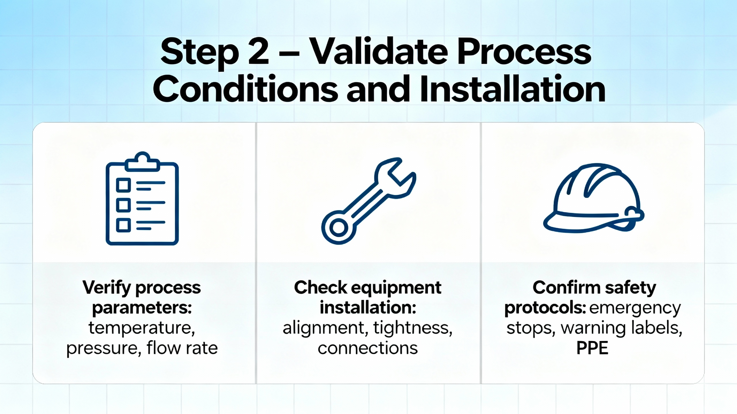
Step 2 – Validate Process Conditions and Installation
Once power, wiring, and configuration have been checked, the next priority is to make sure the meter’s environment and installation are still within what the device can handle. Across the literature from Holykell, Sierra Instruments, Kobold, Turbines Incorporated, Cannon Water, and others, three themes dominate: pipe filling and air, flow profile and location, and mechanical and environmental stress.
Pipe Filling and Air Entrapment
Air and gas pockets are a recurring villain in flow meter troubleshooting. Cannon Water discusses air bubbles in liquid systems as a cause of distorted readings, especially in ultrasonic and magnetic meters. BJSSAE and Manas both note that air bubbles or partially filled pipes can mimic zero flow or intermittent readings. IPEC highlights trapped air as a reason water meters show zero when fluid is clearly moving.
Microsensor points out that electromagnetic meters installed at the top of rising lines or in locations where the pipe is not completely full frequently show unstable readings. Their troubleshooting guidance calls for enabling the empty-pipe alarm with an appropriate resistance threshold and avoiding high points where air accumulates. Soaring Instrument’s ultrasonic guidance also dwells on pipes that are empty or only partially filled, which dramatically weakens the ultrasonic signal.
When you have signal loss or zero readings, physically verify that the meter is installed in a section of pipe that remains full under all operating conditions, and that venting or air elimination is adequate. In some cases, reorienting the meter or adding air eliminators upstreams is the only lasting solution.
Flow Profile, Straight Run, and Location
Poor hydraulics can make a healthy meter look sick. Holykell, Turbines Incorporated, Cannon Water, and IPEC all stress the need for straight pipe runs upstream and downstream to stabilize the flow profile, particularly for velocity-based technologies such as turbine and ultrasonic meters. Turbines Incorporated gives a commonly used guideline of about ten pipe diameters of straight run upstream and five downstream and recommends flow conditioners or straightening vanes when that is not feasible.
Cannon Water and IPEC warn that installing meters too close to pumps, elbows, or reducers can introduce turbulence and distorted profiles that show up as unstable or biased readings. Holykell adds that valves, reducers, and other fittings too close to the meter can also corrupt the measurement, even on advanced meters.
Location relative to pumps is especially important. Control.com experts suggest watching pressure both upstream and downstream of the flow meter to see whether pump pulsation or cavitation correlates with signal instability. In self-flow or low-pressure lines, Microsensor notes that entrained air at high points can cause severe fluctuations.
Vibration, Mechanical Stress, and Mounting
Mechanical stress is frequently overlooked until meters start failing early. Kobold explains that high mechanical vibration leads to sensor drift, electrical noise, and mechanical wear, and offers vibration-resistant designs for such cases. Turbines Incorporated and Knkeglobal describe situations where meters mounted too close to pump outlets or on weak supports experience pump shock and mechanical strain that distorts sensor signals and damages bearings.
Manas and BJSSAE both identify mechanical damage and loose supports as contributors to incorrect readings or failure, especially where pipes move or are subject to impact. The practical lesson is to support the piping so the meter is not carrying line stress, keep it out of direct structural vibration hot spots where possible, and choose ruggedized designs when vibration cannot be avoided.
Temperature, Moisture, and Environment
Temperature extremes and moisture ingress can cause subtle or sudden failures. Knkeglobal and Sierra Instruments both report accuracy problems and failures when meters are used outside their rated temperature range or in environments with large swings. Microsensor warns that in integrated electromagnetic meters operating significantly below ambient or above roughly 212 °F, internal condensation and liner expansion can cause electrode leakage, insulation breakdown, and signal interruption. Their recommendation in such cases is to use split-type designs that separate the sensor in the hot or cold area from the converter electronics.
Ingress and condensation also damage electronics. Turbines Incorporated discusses moisture entering through poorly sealed cable glands or enclosures, while Sierra Instruments advises selecting appropriate environmental protection, such as higher ingress protection ratings and physical shielding, in washdown or outdoor applications. In wet or corrosive areas, verify that cable entries are sealed, low points do not collect standing water, and the enclosure type matches the site conditions.
Step 3 – Technology-Specific Signal Loss Checks
With the basics covered, it becomes useful to focus on the specific meter technology, because each has characteristic ways to lose signal. The sources for ultrasonic, electromagnetic, turbine, positive displacement, differential pressure, and mass flow meters are consistent on this point.
Ultrasonic Flow Meters: Coupling, Alignment, and Parameters
Soaring Instrument focuses specifically on ultrasonic flow meter signal loss and identifies several common causes: poor acoustic coupling between transducers and pipe wall, misaligned transducers, empty or partially filled pipes, wrong parameter settings, and electronic failures. Environmental factors such as temperature extremes, mechanical vibration, electrical interference, and outdoor exposure are also mentioned as contributors to weak or unstable signals.
In practice, the first ultrasonic-specific checks after power and wiring are to confirm that the transducers are firmly coupled with the recommended couplant, that the couplant has not dried or cracked, and that the transducer spacing and orientation match the manufacturer’s geometry for the specific pipe diameter and material. Soaring Instrument recommends reviewing all parameter settings, including pipe size, wall thickness, material, fluid type, transducer type and spacing, and measurement mode.
Advanced diagnostics for ultrasonic meters include reviewing the meter’s reported signal strength and any error codes, analyzing the ultrasonic waveform, and checking logs to see whether signal strength drops correlate with temperature changes, flow regime shifts, or external events. Soaring Instrument suggests that persistent zero signal, highly erratic readings, error codes, and failure to respond to intentional flow changes are strong indicators of deeper transducer or electronic faults.
Their cleaning guidance for clamp-on units is practical: power off the device, carefully dismount the transducers, clean surfaces with a soft cloth and mild detergent, remove old couplant without scratching faces, avoid harsh chemicals or abrasives, then reapply couplant, reinstall, and verify signal strength and stability after restart.
Electromagnetic Flow Meters: Grounding, Empty Pipe, and Electrodes
Electromagnetic meters are widely used in water, wastewater, and chemical service. JM Industrial explains that they measure conductive liquid flow using Faraday’s Law of Electromagnetic Induction and rely on electrodes and liners that must remain clean and intact. The guidance from Microsensor, GAIMC, Manas, and JM Industrial converges on a few key issues: grounding, pipe filling, fouling, and power or configuration mistakes.
Microsensor lists unstable readings due to poor grounding, partially filled pipes, backflow, moisture or vapor on electrodes, liner damage, or electrode corrosion. Their recommendation is to verify proper ground connections and to configure the empty-pipe detection correctly so that the meter alerts on partially filled conditions instead of producing misleading flow values. They also describe cases of no signal output where electrodes are coated with dirt or scale and require cleaning.
JM Industrial emphasizes routine inspection and cleaning of electrodes, using only manufacturer-approved methods and chemicals to avoid damaging sensitive components. Manas and GAIMC echo this focus on corrosion, fouling, and material compatibility, recommending that fluid corrosiveness and abrasiveness be matched with appropriate meter materials.
Electromagnetic meters also depend on reliable power and communications. Microsensor highlights power supply miswiring, undersized supplies, and loose display cables as causes of no display or no output, and details RS485 communication issues when addresses, baud rates, wiring, or modules are wrong. Their troubleshooting steps include confirming that the meter was ordered with the needed communication option, checking RS485 terminal assignments and cable types, and ensuring modules have not loosened in transit or operation.
Turbine and Other Mechanical Meters: Moving Parts and Wear
Turbine flow meters and other mechanical devices such as positive displacement meters are vulnerable to wear, contamination, and hydraulic abuse. Turbines Incorporated describes measurement drift caused by bearing wear and rotor fouling, reduced accuracy from poor straight runs and turbulence, and pressure drop from internal obstructions or incorrect sizing. Their field troubleshooting guide walks through mechanical inspection, including removing the rotor and spinning it by hand to confirm smooth, noise-free rotation, and visually checking blades for chips, cracks, or distortion.
Manas and BJSSAE add common issues such as debris and dirt obstructing the flow path, sensor fouling, and mechanical damage from impacts or vibration. Knkeglobal emphasizes mechanical wear of internal components like rotors, gears, and bearings across mass flow meters as well, recommending scheduled inspections and prompt replacement of worn parts.
Kobold points out that high-viscosity and non-Newtonian fluids are particularly challenging for some mechanical meter types, and recommends positive displacement designs tailored to such media to maintain accuracy. They also note that pulsating flows and bidirectional flows can cause rapidly changing velocities and directions that many meters cannot track accurately without appropriate design.
For mechanical meters that appear to have lost signal, check for blockages, fouling, or seized rotors, verify that upstream filtration is in place where needed, and compare meter size against the actual flow range so that the rotor is neither stalled at low flows nor running excessively fast at normal conditions.
Differential Pressure Flow Systems: Primary Elements and Impulse Piping
Differential pressure flow meters, built around primary elements such as orifice plates, venturi tubes, or wedges, can also exhibit apparent signal loss. Primary Flow Signal’s troubleshooting guide focuses on four categories: low or no output, calibration problems, high or low output, and erratic output. For low or no output, they stress inspecting the primary element for correct installation and physical condition, as well as verifying that sufficient straight pipe exists upstream without changes in diameter or direction.
Another frequent source of trouble is the impulse piping between the primary element and the transmitter. Primary Flow Signal lists reversed pressure connections, leaks or blockages, entrapped gas in liquid service or liquid in gas service, sediment or debris in transmitter flanges, and incorrect valve positions as causes for low, high, or erratic readings. In many of these cases, the transmitter itself is healthy, but the pressure signals it receives are corrupted.
They also remind users that the sensing element inside a transmitter is generally not field repairable; if it is defective after all other causes are eliminated, replacement is required. That reinforces a broader theme: only condemn the transmitter after process, installation, wiring, and configuration have been systematically ruled out.
Step 4 – Use the Right Diagnostic Tools and Data
Good troubleshooting relies as much on simple tools as on experience. The control.com forum contributors recommend breaking the 4–20 mA loop and using a process calibrator as the receiving device to read the transmitter output directly. This isolates the transmitter from the control system and quickly reveals whether the instrument is producing a stable signal. They also suggest checking the power supply and, when available, viewing the signal on an oscilloscope to see noise or dropouts that average readings might hide.
Microsensor discusses using a multimeter to adjust analog output zero, verify power board channel voltages, and test RS485 modules. Primary Flow Signal emphasizes verifying pressure sources and calibrators when transmitter calibration appears faulty, and checking power directly at transmitter terminals.
Another powerful but often underused technique is comparative measurement. Microsensor describes comparing electromagnetic meter readings to other instruments on the same line, such as ultrasonic meters or glass rotameters, while noting that these reference devices have their own error ranges. Sierra Instruments recommends periodic performance checks using independent measurements like tank levels or batch weights for critical services. When signal loss or drift is suspected, temporarily installing a clamp-on ultrasonic meter as a reference, when fluid cleanliness allows, can help distinguish process issues from instrument problems.
Error codes and internal diagnostics, where available, should also be used. Soaring Instrument highlights the value of reviewing error messages, signal strength indications, and logs to distinguish installation, process, and electronic faults. Microsensor’s detailed list of fault conditions in electromagnetic meters illustrates how many issues can be detected and narrowed down through onboard diagnostics if technicians take time to interpret them.
Common Signal Loss Scenarios at a Glance
The following table summarizes some recurring signal-loss scenarios and their typical causes and checks, based on the combined guidance from GAIMC, Microsensor, Soaring Instrument, Turbines Incorporated, BJSSAE, Manas, Primary Flow Signal, and others.
| Symptom | Likely Causes (from field reports and manufacturers) | Initial Checks |
|---|---|---|
| Zero reading with visible flow | Power or wiring issues, broken or disconnected signal cable, faulty pulse transmitter, blocked rotor or sensor, empty or partially filled pipe | Measure supply at meter, inspect cabling and terminations, verify pipe is full, inspect rotor or sensor |
| Intermittent dropouts or spikes | Electrical interference, poor shielding or grounding, loose connections, vibration, pulsating flow, marginal power | Check cable routing and shields, tighten terminals, assess nearby EMI sources, review pump and flow regime |
| Unstable or noisy analog output | Ground loops, insufficient straight run, air entrainment, vibration, partially filled pipe, electromagnetic noise | Verify single-point grounding, check straight-run requirements, remove air, reinforce supports, isolate EMI |
| No communication over RS485 or similar | Wrong options ordered, incorrect addresses or baud rates, wrong terminals, wrong cable type, damaged modules | Confirm meter has the option, verify settings, wiring, and cable specification, reseat or replace modules |
| Low or drifting signal at normal flow | Calibration drift, electrode fouling, rotor wear, scaling or deposits, changing fluid properties | Compare to reference, inspect and clean internals, review calibration and fluid data, schedule recalibration |
This table is not exhaustive, but it reflects patterns repeatedly mentioned across manufacturer guides and independent troubleshooting discussions.
Preventive Strategy: Design Out Future Signal Loss
The most efficient signal-loss troubleshooting campaign is the one you do not need because the system was designed and maintained correctly. Across Holykell, Sierra Instruments, GAIMC, Manas, Kobold, Knkeglobal, Turbines Incorporated, and others, two preventive themes stand out: choosing the right meter and maintaining it intentionally.
On selection and application, Holykell underscores that instrument performance parameters, fluid characteristics, installation and piping conditions, environmental influences, and lifecycle cost must all be defined upfront. Their observation that most problems start at the selection stage is echoed by Sierra Instruments, who emphasize matching technology to volumetric versus mass measurement needs, fluid cleanliness, corrosiveness, and temperature limits.
Kobold reinforces the importance of technology choice for challenging media such as highly viscous or non-Newtonian fluids, recommending positive displacement designs where other meters struggle. Sierra Instruments points out that ultrasonic meters are non-intrusive and accurate for clean fluids but struggle when fluids are contaminated or bubbly, while differential pressure and vortex devices are robust but introduce pressure drop and can foul at low pressures or high viscosities. GAIMC highlights the need to select meters compatible with the specific fluid characteristics and to review specifications before changing media.
On maintenance and calibration, nearly every source makes the same basic recommendation: do not wait for failures. Manas, BJSSAE, and GAIMC recommend regular inspection, cleaning, and calibration, with GAIMC noting annual calibration as a common baseline and more frequent checks for harsh or high-criticality services. Sierra Instruments describes calibration to traceable standards as central to maintaining reliability, and Turbines Incorporated reminds operators that all meters drift over time and that calibration programs, often annual or semiannual for critical services, are necessary.
Preventive measures should also include electrical and environmental protection. Manas and Kleev recommend proper grounding, shielding, and noise filtering to prevent electrical interference, while Knkeglobal and Microsensor advocate for designs that separate sensitive electronics from extreme temperatures and for protecting against condensation and moisture ingress.
From a systems integrator’s perspective, building these practices into project standards and maintenance routines—not as optional extras, but as core requirements—does more to reduce signal-loss incidents than any single troubleshooting trick.
Repair or Replace: Making the Practical Call
Sooner or later, every plant has to decide whether a problematic meter is worth repairing. Turbines Incorporated offers sensible guidance here: minor wear, electronics failures, and pickup coil issues are often economical to repair using replacement parts and professional recalibration, especially when meter bodies are structurally sound. Bearings and rotors are commonly designed to be serviceable, and restoring them can return the instrument to near-original performance.
However, when wear is extensive, problems recur frequently, or the meter’s technology no longer integrates well with modern digital control systems, replacement can be the more practical path. Knkeglobal notes that mass flow meter failures stemming from sensor damage, circuit faults, or severe mechanical wear often require replacement rather than repair, depending on severity and age. GAIMC reminds users that repair versus replacement decisions depend on fault severity, meter age, and economic trade-offs, and that many meters have expected service lives on the order of several years to a decade under proper maintenance.
An experienced integrator looks at three things: how critical the measurement is, how much downtime replacement versus repair will cause, and whether the existing technology still matches the process. If the meter is in a critical dosing loop, if it has a history of recurring faults, or if your process has evolved significantly, renewing the installation with a better matched technology may be the most reliable choice.
Short FAQ
Why does my flow meter read zero when I clearly have flow?
IPEC, BJSSAE, and GAIMC all describe this symptom. Common causes include disconnected or broken signal cables, faulty pulse transmitters or scaler boards, blocked or fouled measuring elements, and air pockets or partially filled pipes. Begin by confirming power and cabling integrity, then verify that the line is full and free of trapped air, and finally inspect the sensor or rotor for fouling or mechanical damage before assuming the transmitter is bad.
How often should I calibrate to avoid signal problems?
GAIMC suggests annual calibration as a common baseline, with more frequent checks in harsh environments or high-criticality applications. Sierra Instruments notes that many users and regulations require regular calibration against traceable standards. Combining manufacturer recommendations with your risk profile is the best approach: critical custody-transfer or safety loops often justify more frequent verification than noncritical monitoring points.
What is one quick way to separate wiring issues from a bad transmitter?
The control.com discussion and Primary Flow Signal both advocate isolating the loop. Disconnect the meter’s output from the control system and use a process calibrator or a known-good measuring device to read the transmitter output directly or to inject a reference signal into the loop. If the transmitter output is stable at the device but not at the control system, the issue lies in wiring or input configuration. If the transmitter output itself is unstable or absent after power and wiring checks, focus on the instrument and its immediate environment.
As a veteran systems integrator, I have rarely seen a flow meter fail in isolation. Signal loss is almost always the visible symptom of a broader issue involving power, grounding, hydraulics, or application fit. When you approach troubleshooting methodically—starting with the electrical basics, examining installation and process conditions, then applying technology-specific checks—you protect your schedule, your budget, and your operators’ trust in the instrumentation.
References
- https://reclaim.cdh.ucla.edu/fetch.php/papersCollection/y0QzuK/Flow-Measurement-Engineering-Handbook.pdf
- https://admisiones.unicah.edu/Resources/mCU4ng/0OK006/abb__flow-meter_manual.pdf
- https://www.bjssae.com/a-common-issues-with-flowmeters-and-how-to-troubleshoot-them.html
- https://holykell.com/5-Reasons-Your-Flowmeter-Is-Inaccurate.html
- https://news.ipecsales.com/5-faqs-on-troubleshooting-your-water-flow-meter-system
- https://www.microsensorcorp.com/Details_common-troubleshooting-for-electromagnetic-flow-meters.html
- https://www.gaimc.com/Newsinfo/flow-meter-faq-common-problems-solutions
- https://www.kleevusa.com/troubleshooting-flow-meters-common-issues-and-effective-solutions/
- https://www.linkedin.com/posts/vizen-solutions1_flowmeasurement-processtroubleshooting-activity-7366696046938292224-DruO
- https://manasmicro.com/common-flowmeter-problems-and-how-to-solve-them/
Keep your system in play!
Top Media Coverage
Categories


Related articles Browse All
-
 amikong NewsSchneider Electric HMIGTO5310: A Powerful Touchscreen Panel for Industrial Automation2025-08-11 16:24:25Overview of the Schneider Electric HMIGTO5310 The Schneider Electric HMIGTO5310 is a high-performance Magelis GTO touchscreen panel designed for industrial automation and infrastructure applications. With a 10.4" TFT LCD display and 640 x 480 VGA resolution, this HMI delivers crisp, clear visu...
 -
 BlogImplementing Vision Systems for Industrial Robots: Enhancing Precision and Automation2025-08-12 11:26:54Industrial robots gain powerful new abilities through vision systems. These systems give robots the sense of sight, so they can understand and react to what is around them. So, robots can perform complex tasks with greater accuracy and flexibility. Automation in manufacturing reaches a new level of ...
 -
 BlogOptimizing PM Schedules Data-Driven Approaches to Preventative Maintenance2025-08-21 18:08:33Moving away from fixed maintenance schedules is a significant operational shift. Companies now use data to guide their maintenance efforts. This change leads to greater efficiency and equipment reliability. The goal is to perform the right task at the right time, based on real information, not just ...


- Q&A
- Policies How to order Part status information Shipping Method Return Policy Warranty Policy Payment Terms
- Asset Recovery
- We Buy Your Equipment. Industry Cases Amikong News Technical Resources Why choose us
- ADDRESS
-
 32D UNITS,GUOMAO BUILDING,NO 388 HUBIN SOUTH ROAD,SIMING DISTRICT,XIAMEN
Leave Your Comment