
-
Please try to be as accurate as possible with your search.
-
We can quote you on 1000s of specialist parts, even if they are not listed on our website.
-
We can't find any results for “”.
I/O Module Communication Loss Repair: Practical Solutions
I/O module communication loss is one of those problems that looks “mysterious” to operators and painfully familiar to anyone who has spent nights on a plant floor. One bad module, one marginal power supply, or one poorly terminated bus segment can take down a packaging line, a mixer, or a filler, even when the PLC and HMI appear healthy.
As a systems integrator, I have seen the same patterns repeat across ControlLogix racks, Siemens S7 islands, AS-i networks, RS485 I/O buses, and newer IO-Link Wireless architectures. The good news is that the failure modes are predictable, and the repair paths are repeatable once you approach them methodically.
This article distills proven practices from real-world case studies and vendor guidance from sources such as Control.com, Industrial Automation Co., RealPars, Domat, ifm, CoreTigo, and several PLC troubleshooting specialists. The focus is not theory, but practical, stepwise repair methods you can apply on a live system without guesswork.
Why I/O Communication Loss Is So Disruptive
I/O modules sit between your PLC and the physical world. They translate sensor states and analog signals into data the CPU can understand and convert CPU decisions into outputs that drive valves, motors, solenoids, and safety devices. When that communication path fails, the PLC stops trusting its own eyes and hands.
Industrial Automation Co. describes how ControlLogix I/O faults disrupt data flow and can cause downtime, safety risks, and bad counts in packaging and pharmaceutical plants. A similar Siemens S7 case study showed a line in a Midwest facility losing communication to its I/O modules during a critical run, putting about $15,000.00 per day of production at risk until the faulty module was replaced.
RealPars points out that roughly three quarters of control system failures are caused by field devices, with the remaining quarter attributed to PLC I/O modules, while PLC programs themselves rarely fail. The implication is important: when you see “I/O communication loss,” you are usually chasing an electrical or network problem, not a logic bug.
I/O modules also fail gradually. GES Repair notes that issues often start as intermittent or misleading events: flickering outputs, nuisance fault codes, sluggish responses, or channels that drop in and out. Operators describe “random trips” long before a module dies completely. If you treat these as operator error or “ghosts in the machine,” the problem is likely to escalate into extended downtime.
What “Communication Loss” Really Means In The Field
Communication loss is not a single failure mode. It is the symptom you see when something breaks at one of several layers: power, field wiring, I/O bus, network, module electronics, or configuration.
Control and troubleshooting guides highlight several distinct categories.
At the electrical layer you see open or short circuits, unstable supplies, and noise. CoreTigo describes short circuits that burn components and shut down I/O channels, and open circuits from disconnected wires that block signals entirely. PLC troubleshooting resources emphasize power supply issues and loose or corroded connections as recurrent root causes.
At the module and channel layer you encounter input tracking failures and output control failures. The module is powered and visible to the PLC, but analog changes are not tracked correctly, or outputs are incorrect or mistimed. CoreTigo points out that such logical failures can create quality and safety risks even when hardware is still “alive.”
At the local I/O bus level, Domat documents how a faulty I/O module power supply that drops to about 6 V can cause the module to continually reset, flooding the RS485 bus with interference. Improper RS485 termination or too many devices with their “bus end” switches turned on can destabilize an otherwise healthy bus as more modules are added.
On device-level networks you see protocol and address issues. Ifm explains that on AS-i networks each node must be simultaneously detected, projected, and active. If any of those states is missing, the master reports a configuration fault even if the wiring looks correct. Solidot shows a CC-Link IE Field Basic example where remote I/O couplers stopped communicating because their start address overlapped the PLC’s local reserved points.
On industrial Ethernet networks you face IP conflicts, cable damage, and firmware mismatches. Industrial Automation Co. describes ControlLogix EtherNet/IP and ControlNet systems where wrong module types, misaddressed I/O, congested networks, or incompatible firmware cause I/O modules to drop off the system.
You repair communication loss efficiently by first deciding which layer you are dealing with. The table below summarizes typical clues and tools.
| Layer or focus | Typical symptom | Main diagnostic tools |
|---|---|---|
| Power and grounding | Resets, hot modules, flickering LEDs | Multimeter, thermal checks, power sizing |
| Field devices and wiring | Inputs or outputs wrong or intermittent | Wiring diagrams, DMM, visual inspection |
| Local I/O bus (RS485, AS-i) | Some or all modules vanish or show bus errors | Bus LEDs, termination switches, converters |
| Ethernet or fieldbus | Remote racks lost, sporadic comms, error codes | Studio 5000, TIA Portal, network diagnostics |
| Addressing and firmware | “Unsupported parameters,” configuration faults | CPU diagnostics, address maps, firmware lists |
With that mental model, you can work through a communication loss incident systematically instead of swapping cards at random.
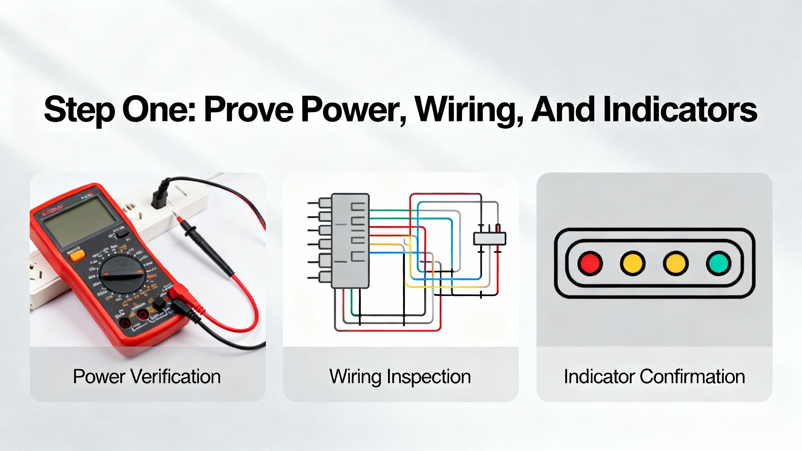
Step One: Prove Power, Wiring, And Indicators
Experienced technicians and integrators all start in the same place: power, connections, and status lights. PLC troubleshooting guides from PLC Department, GIC, RealPars, and Industrial Automation Co. converge on this point, and control-specific sources like Domat and ifm reinforce it for I/O buses and AS-i networks.
Confirm Stable Power At The I/O Rack
Unstable or undersized power supplies are a classic cause of communication loss. Domat describes an I/O module whose supply transformer sagged to about 6 V, causing the module to constantly reset and inject interference into the bus. The symptom on the network resembled random communication noise, but the root cause was simply an undervoltage supply.
PLC troubleshooting references consistently recommend:
Validate power at the I/O rack or bus with a multimeter, not just by looking at a green LED. On 24 V DC systems, measure at the terminals feeding the modules and compare to the specified range. If the supply is marginal under load, I/O communication can fail intermittently as current demand changes.
Compare total I/O and field load against the power supply’s rated capacity. ControlLogix guidance from Industrial Automation Co. emphasizes verifying that the sum of module currents plus field loads leaves adequate margin. When a supply is near its limit, adding one more module or device can push it into a fault condition.
Check grounding and bonding. GIC and PLC Department both note that poor grounding and loose power connections lead to intermittent system-wide failures and can corrupt data or trigger spurious resets. These problems often present as communication issues before they reveal themselves as outright power failures.
If the power supply is undersized or unstable, the repair is straightforward: replace or upgrade it and re-distribute loads as needed before you chase more exotic causes.
Inspect Physical Wiring And Topology
Physical wiring faults are more common than bad modules. PLC troubleshooting resources repeatedly stress visual inspections before deep diagnostics. In practice that means opening the panel, tugging on terminals, and inspecting cable runs.
Industrial Automation Co. recommends checking all terminations for tightness, looking for broken strands, and using continuity tests to identify open conductors in ControlLogix systems. PLC Department and PLC Technician resources add that field cables frequently suffer from corrosion, fraying, or damage caused by vibration and mechanical stress.
On RS485-based I/O buses, Domat advises verifying physical topology and termination. The recommended layout is a line or daisy-chain with termination at both ends, usually activated by DIP switches labeled for bus end settings. If termination is missing or if many intermediate modules have their bus end switches turned on, signal reflections and attenuation can cause modules to disappear from the bus as more devices are added. The repair is simple but precise: identify the true ends of the bus and ensure only those modules are terminated.
Domat also highlights that the choice of RS485 converter matters. Some converters switch too slowly from transmit to receive mode and miss the fast responses from I/O modules, making healthy modules appear faulty. The practical fix is to replace slow converters with faster models specifically designed for the modules in use.
Read What The LEDs Are Telling You
Front-panel LEDs on I/O modules and network devices are not decorative; they are your first diagnostic interface. ControlLogix documentation summarized by Industrial Automation Co. emphasizes three key indicators on many I/O modules: OK, I/O, and Network Status. A solid green OK LED usually means the module’s internal health is good, while flashing or solid red patterns correspond to documented fault codes. An off or red I/O LED can indicate a problem with field device communications. Network Status LEDs show whether the module has a clean connection to the controller or network.
AS-i systems, as described by ifm, rely heavily on LED and node-state diagnostics. Green power and I/O LEDs confirm correct module operation, while local fault indicators signal short circuits, communication problems on the yellow AS-i cable, loss of auxiliary power on the black cable, or overload conditions.
Domat notes that a constantly flashing red transmit LED on an RS485 I/O module is a sign the module is repeatedly trying and failing to communicate, often due to power resets or gross bus faults. Under normal conditions, transmit LEDs flicker briefly as modules respond to controller queries in sequence.
If your LEDs tell you that a module is powered, participating on the bus, but certain channels or nodes are unhealthy, the next step is to distinguish between a failing field device and a failing I/O channel.
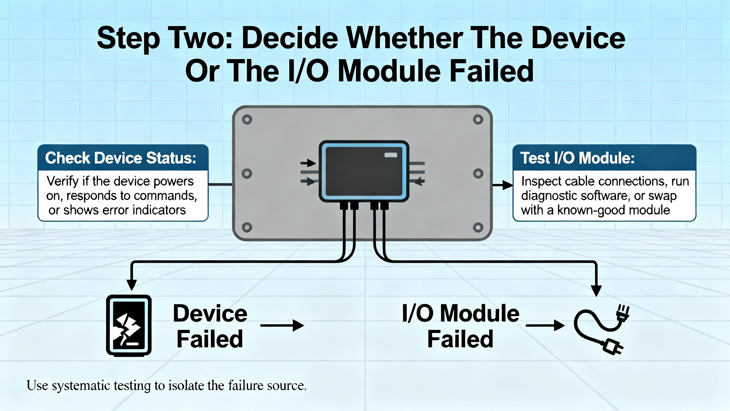
Step Two: Decide Whether The Device Or The I/O Module Failed
RealPars reminds us that about three quarters of control system failures come from field devices and their wiring, with only about a quarter from I/O modules. Yet technicians often replace cards first. That is both expensive and misleading.
The most reliable way to separate device faults from module faults is to measure real currents and voltages under operating conditions. Control.com emphasizes that modern solid-state I/O and sensors do not behave reliably under simple continuity tests. Their internal resistance changes under voltage, so unpowered ohm checks are not a trustworthy way to judge their health.
Use Current-Based Tests On Inputs
For input modules, Control.com recommends using an inline ammeter and a protective resistor to prove whether the input channel can still sink or source current. The process looks like this in practice.
First, verify the module’s supply and common voltage. For sourcing input modules, you should see about 24 V at the common terminal. For sinking modules, the common should be near 0 V before you assume hardware is damaged. This aligns with the “verify COM voltage first” guidance from PLC Department.
Next, temporarily wire an inline ammeter on the input terminal with an appropriate series resistor around 1 kΩ. For a sourcing input, place the meter’s common on the negative supply and measure the current when the input should be ON. A healthy channel typically draws around 5 to 50 mA. For a sinking input, reverse polarity by placing the meter’s common on the positive supply and look for a similar magnitude of current but in the opposite direction.
Zero current on a correctly wired test input, in the presence of proper supply voltage, indicates that the input terminal or the module itself has failed. If the current is in the expected range but the PLC does not register an ON state, you may be dealing with configuration or diagnostics issues rather than an electrical fault.
RealPars reinforces the importance of predicting the expected reading before you touch the meter. Their digital input example with an Allen-Bradley 1756 sinking module and a normally closed push button shows how comparing LED status, ladder logic state, and measured voltage at the input lets you pinpoint whether a failure sits at the module, the field device, or the power supply.
Test Outputs With A Safe Dummy Load
For outputs, Control.com recommends a similar approach using a resistor as a dummy load. Connect a resistor of about 1 kΩ or higher from the output terminal to the appropriate supply rail. Energize the output from the PLC program and measure the current through the resistor with an ammeter.
On a sourcing output, again place the meter’s common on the negative supply. On a sinking output, place it on the positive supply. A healthy 24 V DC output should deliver around 24 mA into a 1 kΩ load. If you read 0 mA while the output is commanded on and supply voltage is present, the output channel or module is likely failed.
RealPars provides a complementary troubleshooting workflow for outputs using live loads. In their example with an Allen-Bradley 1756-OB16D sourcing module driving a lamp through a fuse, a lit output LED with a dark lamp prompts a voltage check between the fuse and lamp. Zero volts suggests an open fuse, while 24 V suggests a downstream issue. Measuring at the lamp’s ground side then distinguishes between a bad lamp and an open or corroded return wire.
They also stress that semiconductor output modules are typically limited to relatively low currents, often up to about 2 A, and should not directly drive large inductive loads. Using interposing relays to control motors and heavy loads protects the module and avoids premature failure that might be misinterpreted as “random” communication loss.
Validate Sensors And Polarized Devices
Many perceived I/O communication problems trace back to miswired or misapplied sensors rather than module failures. Control.com notes that most NPN or PNP proximity sensors in industrial settings are three-wire devices with positive, negative, and load connections. Actual sensor electronics rarely fail outright. More often, the supply is missing, miswired, or of the wrong voltage.
Before suspecting an input card, verify supply voltage between the sensor’s positive and negative leads and confirm that it matches the sensor’s rated range, such as 10 to 30 V DC or 120 V AC. Different voltage models can look physically identical, and applying the wrong supply type or level can cause unreliable behavior or fatal damage.
To test sensor operation, Control.com suggests using the same 1 kΩ resistor on the load wire with an ammeter. With the sensor deactivated, current should be essentially zero. When the target is present, a healthy PNP sensor will source about 24 mA with the meter’s common on the negative supply, while an NPN sensor will sink a similar current with the common on the positive supply. Built-in sensor LEDs, when present, offer an extra visual check.
If both sensor supply and load current behave correctly yet the input module does not see the change, the fault is likely inside the module or in the wiring between sensor and rack.
Do not overlook electrical noise. Control.com and PLC Technician resources warn that inductive devices such as motors, coils, and solenoids can induce spikes on nearby wiring, leading to false or momentary sensor activations that look like communication glitches. Good practice includes using shielded sensor cables, such as shielded M12 quick-disconnects, and routing control and sensor wiring away from high-current inductive loads whenever layout allows.
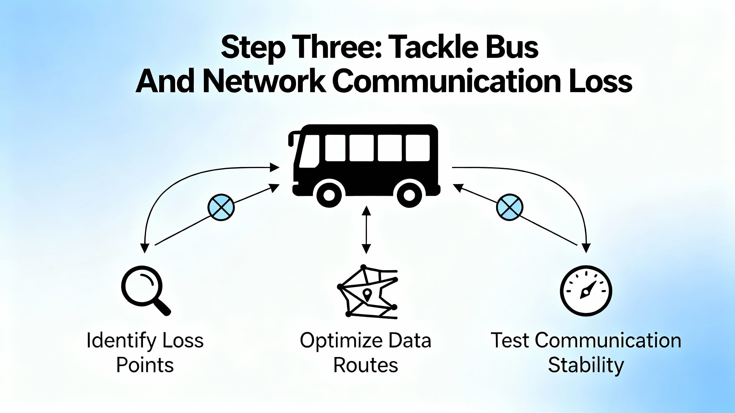
Step Three: Tackle Bus And Network Communication Loss
Once you are confident that local power, wiring, and channel-level behavior are sound, shift your attention to the I/O bus and network pathways. Here, the failure modes differ by technology, but the troubleshooting logic is similar.
Local Buses: RS485 And Proprietary I/O Networks
Domat’s guidance on I/O bus communication problems highlights two recurring issues: power instability at one module and incorrect bus termination. A resetting module injects noise, and incorrect termination distorts signals.
If a module’s transmit LED flashes constantly red, suspect a failing power supply or a module that is repeatedly rebooting. Confirm its local supply voltage and temperature. Replace the supply or module if necessary.
Then walk the bus, verifying that only the first and last modules have their bus end or termination switches turned on. If many modules are terminated, you effectively overload the line with termination resistances and reduce signal margins. Clear labeling and a bus layout drawing save significant time here.
Finally, check the RS485 converter or interface device. Domat reports that some general-purpose converters switch slowly between transmit and receive states, causing them to miss the fast replies from I/O modules. This can be especially problematic with newer, faster modules. Replacing a slow converter with a recommended fast-switching interface has resolved many otherwise puzzling communication losses.
AS-i Networks: Node States And Cable Integrity
On AS-i networks, ifm describes a simple but powerful diagnostic model based on node states and LED indicators. Each node progresses through three states: detected, projected, and active. A healthy system requires each node to be simultaneously detected by the master, taught to the master configuration, and active with an assigned address.
When communication problems appear, start by inspecting each AS-i module for physical damage and verifying that green power and I/O LEDs are lit. Then review the node list to see which states are missing. If a node is detected but not projected, it may not have been properly configured. If projected but not detected, a wiring or address problem is likely. Local fault indicators at the node can signal short circuits on I/O points, communication problems on the yellow AS-i cable, loss of auxiliary power on the black cable, or overload conditions.
Repair actions typically include re-terminating or replacing damaged cable segments, tightening screw terminals, resolving short circuits on field devices, and re-teaching nodes to the AS-i master.
Ethernet-Based Remote I/O: ControlLogix, S7, And CC-Link IE
On Ethernet networks, structured software diagnostics are your best friend. Industrial Automation Co. emphasizes the use of Studio 5000 for ControlLogix systems: Module Properties pages, controller fault logs, and monitoring of input and output tags provide a live view of I/O health. When a module or remote rack drops, the fault log often points to specific causes such as connection timeouts, IP conflicts, or firmware incompatibilities.
For Siemens S7 families, Industrial Automation Co. recommends using TIA Portal’s Diagnostic Buffer and Hardware Diagnostics. Engineers verify physical connections, confirm stable 24 V DC power to both PLC and I/O modules, and use TIA Portal’s “Accessible Devices” to ensure that all nodes on the PROFINET network are visible and correctly addressed. Network-related issues can involve firewalls blocking traffic, closed TCP port 102 for PROFINET, damaged Ethernet cables, or misconfigured IP addresses.
Solidot’s example on CC-Link IE Field Basic illustrates that even with good wiring, remote I/O can fail to exchange data when address mapping is misconfigured. The CPU diagnostic message “CC-Link IE Field Basic network has unsupported parameters” pointed to a subtle issue: the start address chosen for a remote I/O coupler overlapped with reserved local I/O points. Adjusting the coupler’s start address and refresh area to avoid reserved ranges resolved the communication fault.
Across all Ethernet-based remote I/O systems, best practice includes checking the following:
Confirm that each network device has a unique and correct IP address within the expected subnet.
Inspect network cables for physical damage, kinks, or crushed sections, particularly in high-vibration areas.
Monitor network traffic for congestion or collisions using appropriate tools when intermittent communication loss correlates with high production activity.
Verify firmware compatibility between controllers, communication modules, and I/O devices, since mismatched firmware can cause intermittent or unexplained behavior.
When a module is clearly failed or obsolete, follow the example from the S7 case study: swap it with a known-good replacement promptly to restore production, then use the detailed diagnostics to prevent recurrence.
Repair Or Replace? Making The Call On I/O Modules
Once you have isolated a faulty I/O module, you need to decide whether to repair or replace it. GES Repair provides a useful framework based on the extent of damage, cost, availability, and long-term reliability.
Minor and localized failures, such as damaged connectors, blown capacitors, or corroded contacts, are often good candidates for repair. Repair is especially attractive when it can be completed faster than sourcing a new unit, minimizing downtime, or when dealing with legacy or discontinued modules that are difficult or expensive to replace. Specialist repair shops can replace discrete components and restore modules at a lower cost than full replacement.
Replacement becomes the better option when modules show extensive wear, repeated failures, multiple component failures, or clear end-of-life degradation. Continuing to patch such hardware may keep it running briefly, but it increases the risk of future, harder-to-diagnose faults. If a module is no longer manufactured or supported, replacing it with a modern equivalent can reduce recurring faults and future support risk.
Industrial Automation Co. describes a packaging plant that lost communication with its S7-1500 I/O modules during a critical run, putting substantial daily revenue at risk. A replacement ET200SP module shipped by late morning, and with remote guidance, the line was running again in under six hours under a generous warranty. That case illustrates that having a trusted supplier with stocked spares and fast logistics can turn a major communication loss into a short interruption.
Decision-making here should be prompt. GES Repair warns that delaying diagnosis and action on small malfunctions allows localized I/O problems to cascade into broader system failures, increasing total cost of ownership. In practice, once you can reproduce a module fault and see consistent abnormal behavior, lean decisively either toward professional repair or toward replacement and document the rationale.
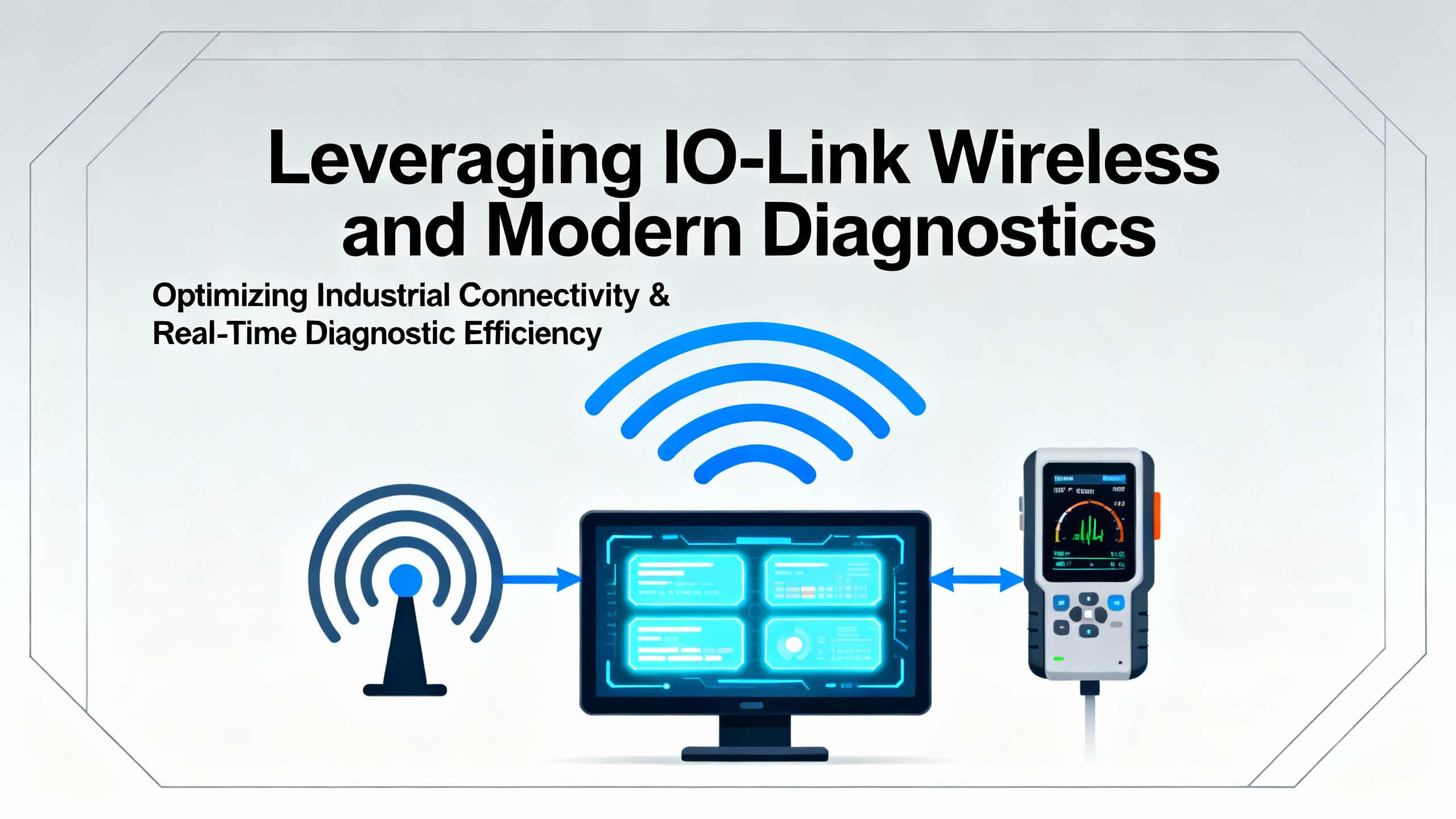
Leveraging IO-Link Wireless And Modern Diagnostics
Traditional wired I/O modules and buses are not going away, but newer technologies can significantly reduce time to detect and repair communication issues. CoreTigo positions IO-Link Wireless as a bidirectional protocol that not only carries I/O data but also serves as a diagnostic and condition monitoring channel.
In the context of communication loss repair, there are two practical benefits.
First, IO-Link Wireless devices can act as plug-and-play replacements for malfunctioning wired I/O channels, enabling temporary workarounds that keep production running while permanent fixes are arranged. Because IO-Link Wireless relies on an IO-Link Wireless Master rather than a fixed bus cable, re-routing or reassigning I/O points is often faster than rewiring.
Second, IO-Link Wireless supports continuous condition monitoring and higher-level IIoT applications. Instead of verifying module health only at commissioning or during failure events, you can track signal quality, error counts, and environmental parameters over time. Combined with analytics, this allows you to spot degrading performance before it appears as a hard communication fault.
CoreTigo’s article highlights how environmental stressors such as temperature extremes, humidity and corrosion, vibration, and physical impact all contribute to I/O failures. By combining ruggedized hardware with continuous monitoring, and guided by experienced engineering leadership such as their technical expert Reut, plants can move from reactive repair to predictive intervention.
Preventing The Next Communication Loss
Repairing an I/O communication failure under pressure is an important skill. Preventing the next one is what makes you a reliable project partner.
Several themes recur across PLC troubleshooting sources, and they are worth integrating into your maintenance and design standards.
Preventive maintenance schedules matter. PLC Technician guidance and PLC Department recommendations both argue for regular inspections focused on power supplies, I/O modules, and communication modules at least every six months, and more frequently in harsh environments. These inspections should include visual checks for dust, corrosion, and physical damage, tightening of electrical connections, and cleaning or replacement of filters and cooling components to prevent overheating.
Environmental control is a long-term investment. Articles from PLC Technician and GIC stress that excessive heat, moisture, and dust degrade both PLCs and I/O over time. Keeping hardware in clean, temperature-controlled enclosures and keeping backup storage away from interference, heat, and humidity reduces memory corruption and premature hardware failures.
Noise management is not optional. EMI and RFI from large motors, lightning, antennas, and handheld transmitters can interfere with PLCs and I/O modules. Recommended mitigations include limiting the use of handheld RF devices near control equipment, physically segregating noisy machinery from control panels, and improving shielding, grounding, and power conditioning.
Backup and recovery capabilities are part of communication reliability. Power disruptions, blackouts, and grid failures can crash PLCs and corrupt memory. Installing uninterruptible power supplies or backup generators that provide enough ride-through for controlled shutdowns, and maintaining up-to-date backups of PLC programs and configurations, mean that a communication loss does not become a prolonged restart effort.
Network hygiene matters as much as cabling. Vista Projects and Industrial Automation Co. both call out protocol mismatches, firmware incompatibilities, and misaligned IP addressing as recurring causes of communication issues. Keeping firmware aligned with software tools, documenting address allocations, and periodically reviewing configurations against manufacturer recommendations will prevent many invisible problems from maturing into visible failures.
Finally, structured troubleshooting and documentation close the loop. RealPars, Vista Projects, and PLC troubleshooting guides all emphasize methodical trial and error, changing one variable at a time, verifying fixes, and documenting both the problem and the solution. Over time, this builds a local knowledge base tailored to your equipment, not just generic vendor advice.

FAQ: Field-Proven Answers To Common Questions
Q: When a production line stops due to I/O communication loss, what is the fastest place to start?
A: Begin at the basics: verify stable power to the PLC and I/O racks, inspect wiring and terminations, and read module and network LEDs. Sources such as Industrial Automation Co., PLC Department, and Domat repeatedly show that many outages are resolved at this level before sophisticated diagnostics are needed. Once power and wiring are proven, use tools like Studio 5000, TIA Portal, AS-i diagnostics, or CC-Link IE CPU messages to pinpoint the next layer.
Q: How long should I troubleshoot a suspect I/O module before swapping it?
A: After you have confirmed proper supply voltages, performed input and output current tests as described by Control.com, and ruled out field device and wiring issues using the RealPars-style workflows, a module that still behaves abnormally is a strong candidate for replacement. GES Repair recommends deciding promptly between repair and replacement once you see consistent symptoms, rather than spending excessive time on a module that has clearly reached end-of-life.
Q: Do I need to redesign everything around IO-Link Wireless or newer protocols to improve reliability?
A: Not necessarily. CoreTigo presents IO-Link Wireless as a powerful tool for faster diagnostics, temporary workarounds, and continuous condition monitoring, especially in challenging environments. However, many communication loss problems are solved by applying rigorous maintenance, power sizing, wiring practices, and documented troubleshooting to existing wired systems. A pragmatic approach is to integrate modern technologies selectively where they clearly reduce downtime or unlock monitoring you cannot easily achieve with the installed base.
Reliable I/O communication is not magic; it is the cumulative result of solid design, disciplined maintenance, and systematic troubleshooting. When you approach communication loss as a layered problem and repair each layer with the right tools, you shorten outages, protect safety, and earn the trust of operators and managers who just want the line to run. As a systems integrator and project partner, that trust is the most valuable piece of hardware you will ever install.
References
- https://ece.uah.edu/~gaede/cpe633/08s_cpe633_chap7.pdf
- https://upcommons.upc.edu/bitstreams/27e15f7b-cd9a-4420-9fa6-086986cf07ce/download
- https://courses.grainger.illinois.edu/cs241/sp2010/lectures/36-IO.pdf
- https://www.plctalk.net/forums/threads/best-practice-for-ethernet-i-o-communication-fault.110396/
- https://www.coretigo.com/how-to-recover-from-an-i-o-module-inefficient-production/
- https://www.domat-int.com/en/i-o-bus-communication-most-common-problems
- https://www.gicindia.com/plc-troubleshooting-tips-common-issues-and-how-to-resolve-them/
- https://www.plctechnician.com/news-blog/five-common-issues-plcs-how-solve-them
- https://www.realpars.com/blog/plc-digital-io-troubleshooting
- https://www.vistaprojects.com/how-to-troubleshoot-plc-errors/
Keep your system in play!
Top Media Coverage
Categories


Related articles Browse All
-
 amikong NewsSchneider Electric HMIGTO5310: A Powerful Touchscreen Panel for Industrial Automation2025-08-11 16:24:25Overview of the Schneider Electric HMIGTO5310 The Schneider Electric HMIGTO5310 is a high-performance Magelis GTO touchscreen panel designed for industrial automation and infrastructure applications. With a 10.4" TFT LCD display and 640 x 480 VGA resolution, this HMI delivers crisp, clear visu...
 -
 BlogImplementing Vision Systems for Industrial Robots: Enhancing Precision and Automation2025-08-12 11:26:54Industrial robots gain powerful new abilities through vision systems. These systems give robots the sense of sight, so they can understand and react to what is around them. So, robots can perform complex tasks with greater accuracy and flexibility. Automation in manufacturing reaches a new level of ...
 -
 BlogOptimizing PM Schedules Data-Driven Approaches to Preventative Maintenance2025-08-21 18:08:33Moving away from fixed maintenance schedules is a significant operational shift. Companies now use data to guide their maintenance efforts. This change leads to greater efficiency and equipment reliability. The goal is to perform the right task at the right time, based on real information, not just ...


- Q&A
- Policies How to order Part status information Shipping Method Return Policy Warranty Policy Payment Terms
- Asset Recovery
- We Buy Your Equipment. Industry Cases Amikong News Technical Resources Why choose us
- Registered Address
-
32D Guomao Building, No.388, Hubin south Road, Siming district, Xiamen,Fujian, China

Leave Your Comment