
-
Please try to be as accurate as possible with your search.
-
We can quote you on 1000s of specialist parts, even if they are not listed on our website.
-
We can't find any results for “”.
Thermocouple Input 8 Channel with Cold Junction Compensation Technology
When you move from one or two thermocouple loops to an eight‑channel input module, problems that were “good enough” on the bench can quietly become plant‑wide headaches. I have seen multi‑zone ovens run 40–50°F off spec, not because the sensors were bad, but because the cold junction on a crowded input card was never treated as a first‑class measurement. If you want eight channels of reliable thermocouple data on a PLC or data acquisition system, you have to understand both the thermocouple and the cold junction compensation behind it.
This article walks through how thermocouple input works, why cold junction compensation (CJC) is non‑negotiable, and what really matters in an eight‑channel thermocouple module. The focus is practical: what you should look for in hardware and how to install and commission it so the numbers you log are the numbers your process actually sees.
Thermocouple Basics You Actually Need
How a Thermocouple Really Measures Temperature
A thermocouple is one of the simplest sensors in the plant: two dissimilar metals welded at one end, the measuring or hot junction. According to classic thermocouple theory and sources such as National Instruments and Analog Devices, the pair generates a small electromotive force when there is a temperature difference between the hot junction out in the process and the cold or reference junction where the wires land on copper in your module. This is the Seebeck effect.
Two points are critical for system design. First, the signal is tiny. A common type K thermocouple produces only on the order of a few tens of microvolts per degree Fahrenheit near room temperature. Second, the sensor does not measure an absolute temperature. It measures the difference between the hot junction and the cold junction. If you do not know the temperature at the cold junction and do not compensate for it, you do not know the true process temperature.
Thermocouples are attractive in multi‑channel modules because, as the Instrunexus and Analog Devices notes emphasize, they are rugged, inexpensive, self‑powered, and cover a very wide range, roughly from cryogenic conditions up to well over 3,000°F depending on type. That makes an eight‑channel thermocouple card a natural fit for furnaces, kilns, engines, and industrial ovens where you want many measurement points and you are willing to trade some accuracy and complexity for range and robustness.
Common Thermocouple Types and Where They Fit
In practice, you do not design an eight‑channel input around a generic “thermocouple.” You design around specific standardized types with known materials and characteristics. Typical types, summarized from Instrunexus and Analog Devices, look like this.
| Type | Materials (positive / negative) | Approx range (°F) | Approx sensitivity near room temp (µV/°F) | Typical uses |
|---|---|---|---|---|
| J | Iron / Constantan | about −40 to 1,380 | about 31 | General industrial, older equipment, oxidizing environments |
| K | Chromel / Alumel | about −330 to 2,280 | about 23 | General purpose, furnaces, engines, kilns, wide use in process plants |
| T | Copper / Constantan | about −330 to 660 | about 24 | Food, environmental, cryogenic work where moisture is present |
| E | Chromel / Constantan | about −330 to 1,650 | about 38 | Higher sensitivity, low‑temperature and cryogenic work |
| N | Nicrosil / Nisil | about −330 to 2,370 | about 22 | High‑temperature, improved stability over K in harsh service |
| R/S/B | Noble metals (platinum‑based) | roughly 0 to 3,270 | about 3 to 6 | Very high temperature furnaces, glass and metallurgy |
The wide range and ruggedness are why nearly two‑thirds of industrial temperature points in the United States still use thermocouples, as noted in Thermal Processing. The tradeoffs are just as important. Compared with RTDs and thermistors, thermocouples are more nonlinear, more susceptible to electrical noise, and typically offer only medium accuracy. They also drift with age and high‑temperature exposure, so long‑term critical loops require calibration and occasional replacement.
In an eight‑channel module you gain density and lower cost per point, but you also multiply the number of tiny, noisy signals that have to share analog front‑end resources. That is where cold junction design and signal conditioning make or break the product.
Why Cold Junction Compensation Is Non‑Negotiable
What the Cold Junction Really Is
The cold junction is not a mystical point in a datasheet. It is the physical place where your thermocouple metals transition into copper: usually the screw terminals or connector on the eight‑channel card, and then the copper traces just behind them.
Thermocouple reference tables published by bodies such as NIST and the former National Bureau of Standards assume that this reference junction sits at the ice point, 32°F. In classical lab work, you literally plunged the cold junction into an ice bath to make this true. In the real world, your panel or data acquisition box sits in a control room or on a mezzanine and the terminals float somewhere between winter nights and summer afternoons.
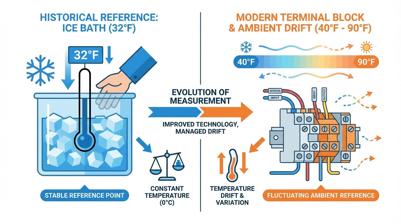
National Instruments and other vendors are very clear on the impact. Because the thermocouple only measures the difference between hot and cold junction, any error in the assumed cold junction temperature shows up almost one‑for‑one in the indicated process temperature. If your eight‑channel module silently assumes the cold junction is held at 32°F, but the terminals are actually at about 77°F, you have introduced roughly a 45°F error before you even start worrying about sensor tolerances or noise.
That is the problem cold junction compensation is designed to solve.
How Cold Junction Compensation Works
Cold junction compensation replaces the physical ice bath with an electronic equivalent. Sources from Fluke, Advanced Energy, and DwyerOmega all describe the same core idea.
First, a separate temperature sensor sits at or very near the thermocouple terminals on the card. Depending on the design, this may be a platinum RTD, a thermistor, a silicon temperature‑sensing IC, or even a diode sensor. National Instruments terminal blocks, for example, often use a factory‑calibrated sensor mounted on the board right next to the thermocouple connections. Kistler describes similar practice with integrated thermistors or diodes in the input stage.
Second, the module measures this cold junction sensor and converts that reading into an equivalent thermocouple voltage referenced to 32°F using standard thermocouple tables or polynomials. In other words, the firmware asks: “If I had a thermocouple whose hot junction was at 32°F and whose cold junction was at the current terminal temperature, what voltage would I see?”
Third, the module adds that computed cold junction voltage to the actual thermocouple voltage coming from the field. Thanks to what Thermal Processing calls the law of successive temperatures, this sum corresponds to the voltage that a thermocouple would produce if its cold junction were physically at 32°F and its hot junction were at the actual process temperature.
Finally, the corrected total voltage is converted to a temperature using the same tables or polynomial equations.
If the cold junction is below 32°F the compensation term is subtracted instead of added, but the principle is the same: measure the terminal temperature once, turn that into an equivalent thermocouple voltage, and mathematically move your reference to the ice point.
How Much Error a Bad Cold Junction Adds
Several sources quantify what happens when cold junction compensation is wrong or ignored. The archived National Instruments knowledge base points out that if the cold junction is at about 77°F but you treat it as 32°F, you will be off by roughly 45°F. DwyerOmega gives a concrete example: a process at about 752°F with a cold junction around 86°F produces a thermocouple voltage corresponding to a differential of about 666°F. If the instrument assumes a 32°F reference, the indicated hot junction temperature will be around 718°F, about 34°F low.
Cold junction sensor accuracy matters just as much. All About Circuits and Analog Devices note that for a typical type K thermocouple, an error of about 1°F at the cold junction produces roughly a 1°F error in the final reported temperature, because the Seebeck coefficient is nearly constant over small ranges. Modern integrated thermocouple interface ICs often specify cold junction accuracy on the order of around ±2°F to ±4°F over a wide ambient range; that accuracy can dominate the overall module performance.
In an eight‑channel module where every channel shares one or two cold junction sensors, a poorly placed or slow sensor, or a hot spot near a power component, can bias all eight readings at once. This is why serious vendors and application notes put so much emphasis on isothermal design: they group all thermocouple‑to‑copper transitions in a tight, well‑coupled region, shield that area from drafts and hot components, and tie the cold junction sensor thermally to the terminals.
Inside an Eight‑Channel Thermocouple Input with CJC
Signal Path from Tip to Controller
Although packaging varies, the internal signal chain of a modern eight‑channel thermocouple module with cold junction compensation follows a fairly standard pattern that matches the guidance from Analog Devices, Maxim Integrated, and others.
Out in the field, each thermocouple loop brings a few millivolts back to the input card. At the terminal block the thermocouple wires meet copper, forming the cold junction. Immediately behind the terminals, the card routes each pair as a differential signal into a low‑noise analog front end. This is often an instrumentation amplifier or the front end of a precision delta‑sigma ADC.
Because thermocouple signals are so small and noisy, the analog front end has to focus on low offset voltage, low bias current, and high common‑mode rejection. The Analog Devices application notes recommend gains on the order of 100 or more, along with radio‑frequency filters at the input and strong rejection of 50/60 Hz mains interference. Many modern delta‑sigma ADCs integrate the programmable gain amplifier and digital filtering, which makes eight‑channel scanning practical without an external analog multiplexer farm.
Parallel to these eight thermocouple channels, one or more cold junction sensors feed either an internal ADC channel or a dedicated sensor interface. In one Maxim example, a temperature‑sensing IC sits near the terminals and its analog output is digitized alongside the thermocouple voltages. In others, the ADC includes its own on‑chip temperature sensor located close to the package pins.
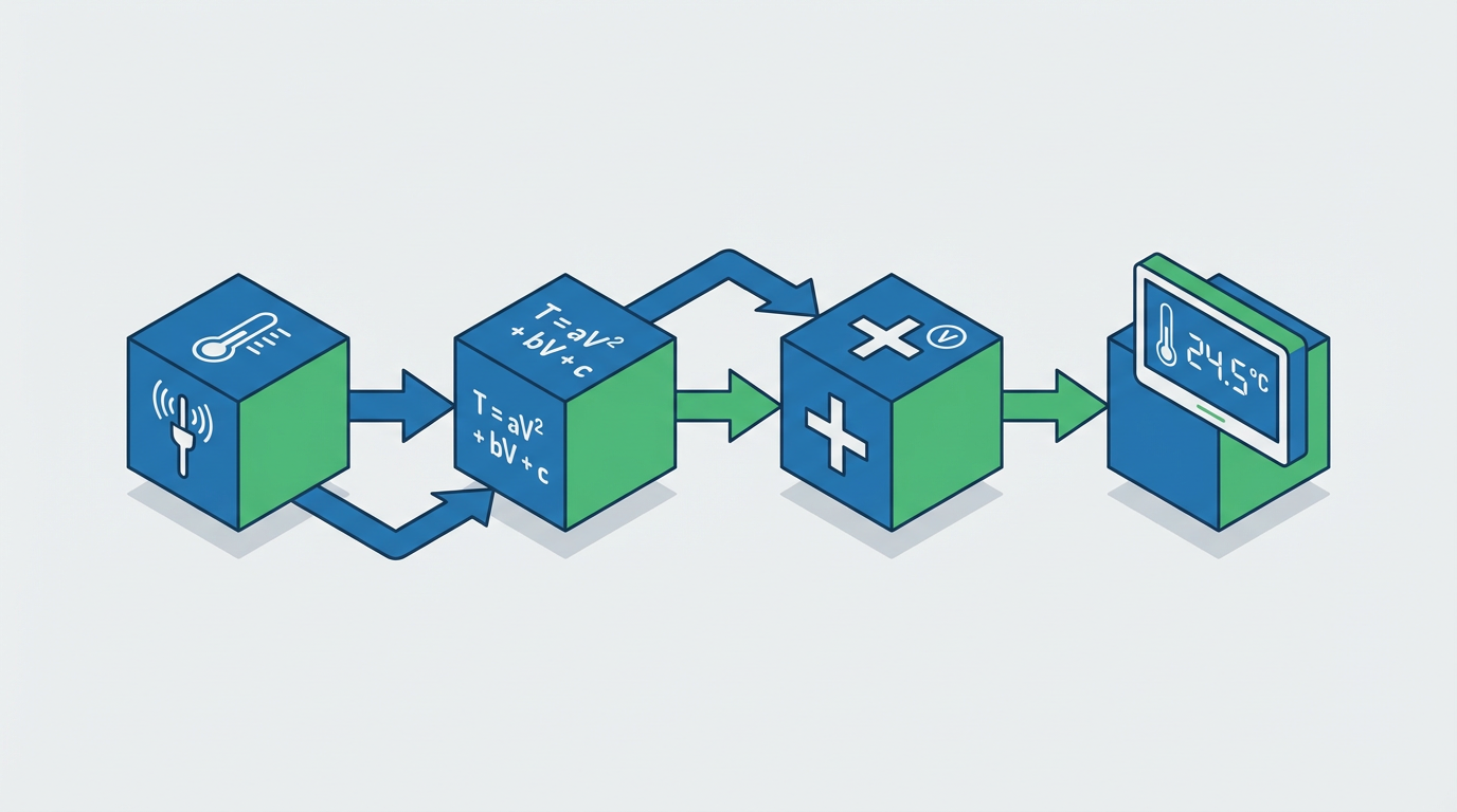
From there, firmware does the rest. It converts the cold junction reading into an equivalent thermocouple voltage using stored coefficients or tables, combines that with the measured thermocouple voltage, and then runs an inverse polynomial or lookup to obtain hot junction temperature. An educational paper from the Polytechnic of Bari describes this exact sequence: use a direct polynomial to compute the cold junction’s equivalent voltage, add it to the hot junction voltage, and then apply the inverse polynomial to get the process temperature.
On some eight‑channel modules, this math happens on the card and the PLC or PC sees scaled engineering units per channel. On others, particularly flexible DAQ systems, the module returns raw or lightly scaled values and the driver library (for example NI‑DAQmx in the National Instruments world) performs thermocouple type selection, CJC, and linearization in software.
Per‑Channel vs Per‑Block Cold Junction Sensing
Most practical eight‑channel thermocouple cards do not carry eight separate cold junction sensors. Instead, they rely on shared sensing at the connector. National Instruments documentation describes several arrangements: modules with one built‑in CJC sensor on the terminal block, modules that expect an external CJC sensor wired to one analog input, and systems that assume a constant reference when the cold junction is physically controlled at a known temperature.
The general rule, which NI and others stress, is that all thermocouples that share a cold junction sensor should experience the same terminal temperature. In a typical compact I/O slice with eight thermocouple channels on one connector, a single well‑placed sensor is appropriate. In larger systems with multiple terminal blocks or remote junction boxes, each cluster of connections should have its own CJC sensor or its own task configuration so that compensation is not incorrectly shared across physically different locations.
If you ever see an eight‑channel module spec that offers only one CJC sensor but expects you to land thermocouples from multiple cabinets or enclosures on it, consider that a red flag. The cold junction reading will be correct only for the thermal environment around the sensor, not for all those remote junctions.
Noise, Grounding, and Isolation in Multi‑Channel Cards
With eight thermocouples entering one card, grounding and noise control deserve as much attention as cold junction design. The Analog Dialogue series from Analog Devices highlights that thermocouples are microvolt‑level sources that run through long leads in electrically hostile environments. Without differential inputs and proper filtering, interference can swamp small temperature changes.
Grounded probe tips can create ground loops if they tie a high‑energy structure into the measurement ground. Insulated tips avoid that but require a defined bias path in the input amplifier so the differential pair does not float. Eight channels with mixed grounding schemes on one non‑isolated card are an invitation to intermittent, cross‑coupled faults.
Thermal Processing points to additional error sources that are especially relevant on dense cards: non‑isothermal junctions at the terminals, temperature gradients along copper traces, heat from power‑dissipating components near one side of a connector, unstable air currents, and insufficient warm‑up time. In our projects we have had good results treating an eight‑channel thermocouple slice more like an analog measurement instrument than a generic I/O block: keep high‑dissipation power electronics off the same PCB area, provide ventilation that avoids direct drafts on the terminals, and allow the module a defined warm‑up period before you capture baseline data.
Isolation strategy is another practical point. Some modules provide channel‑to‑channel isolation, but many provide only group‑to‑bus isolation for all eight inputs. Neither is wrong; however, if you know you have multiple grounded thermocouples at different potentials, a non‑isolated card can easily violate common‑mode limits and saturate the amplifiers. Reading the small print and matching isolation to the plant grounding reality matters much more than the marketing headline.
Thermocouples, RTDs, and Thermistors on Multi‑Channel Inputs
Thermocouple‑only cards are popular because of their range and robustness, but they are not the only option. Instrunexus and Pico Technology both lay out the broader landscape: thermocouples offer the broadest range and ruggedness, RTDs offer higher accuracy and better linearity over a moderate range, and thermistors provide very high accuracy over a narrower range with less ruggedness.
A concise comparison in Fahrenheit terms helps frame eight‑channel module decisions.
| Sensor family | Typical range (°F) | Typical accuracy class | Linearity and stability | Ruggedness and notes |
|---|---|---|---|---|
| Thermocouple | about −330 to 3,270 across types | often around ±2°F or more without calibration | Poor linearity, drift at high temperature, requires CJC and tables | Very rugged, fast response, cheap wiring, ideal for harsh and very hot zones |
| RTD (platinum) | about −420 to 1,200 | can reach about ±0.1 to ±0.4°F with good hardware and calibration | Very linear and stable, good long‑term behavior | Less tolerant of vibration and mechanical abuse, requires excitation current and careful wiring |
| Thermistor | about −150 to 300 | can reach about ±0.2°F or better over a limited span | Highly nonlinear, but very sensitive in a narrow band | Good for compact assemblies, not for very high temperatures, more fragile than thermocouples |
On an eight‑channel temperature card, thermocouples shine when your process includes very hot zones, big gradients, or aggressive atmospheres, or when you already have installed thermocouple probes in the field. If you are instrumenting a test stand or calibration bath in the 70–250°F range and care about fraction‑of‑degree accuracy, an RTD‑based multi‑channel module may be simpler and more accurate because it avoids CJC entirely.
From the systems integrator’s perspective, the key is to avoid mixing design intents. If the marketing sheet promises an eight‑channel thermocouple input that does everything from −300°F cryogenics to 2,000°F kilns with laboratory accuracy, be skeptical. The thermocouple physics, cold junction accuracy, and real plant environments rarely support that without careful calibration and a clear error budget.
Practical Installation and Commissioning Advice
Wiring and Termination Practices That Actually Matter
The best eight‑channel thermocouple input in the catalog cannot rescue poor field wiring. The research literature and vendor guidance converge on a few practices that consistently pay off.
Use proper thermocouple extension or compensating cable all the way from the probe head to the input module. Mixing in ordinary copper for convenience introduces extra junctions of dissimilar metals, and unless those junctions are perfectly isothermal, they generate unwanted thermoelectric voltages that defeat cold junction compensation. Thermal Processing and National Instruments both stress keeping all thermocouple‑to‑copper transitions within a small, thermally uniform region.
Keep each thermocouple pair twisted and, in electrically noisy areas, shielded. Route them away from high‑current motor leads, variable‑frequency drives, and contactor bundles. Pico Technology highlights how mains pickup and switching noise can easily spoil microvolt‑level signals if you treat thermocouple pairs like generic control wiring.
At the input card, land all eight thermocouples on the designated terminals and avoid creative “field fixes” such as wire‑nut splices of different alloys. Make sure the cold junction region is as isothermal as the mechanical design allows. That often means mounting the eight‑channel card away from hot components, adding simple shielding plates to block radiant heat, and making sure air flow is gentle rather than a direct blast.
In the process, remember that you are always measuring the sensor’s temperature, not some idealized “process point.” Pico’s examples show how large, poorly immersed probes can cool a hot fluid locally and read low. In multi‑channel thermocouple systems, it is common to see adjacent channels disagree by several degrees because one probe is properly immersed and the neighboring one is partly in stagnant air or touching a cold wall.
Configuration and Scaling in the Control System
Once the wiring is in place, configuration is where many eight‑channel modules get misused. Following the recommendations from National Instruments and Fluke, you should verify at least four things for each channel: the thermocouple type, the cold junction source, the units, and any linearization or filtering options.
Thermocouple type is straightforward but easy to get wrong when a panel mixes J and K or other types. The lookup tables, polynomials, and even cold junction conversion are type‑dependent. In an NI environment, for example, selecting type J versus type K changes the entire math path. On a generic PLC analog card, the distinction may be buried in a configuration register.
Cold junction source must match the hardware. If the card has an internal CJC sensor, the safest choice is to use that internal source and leave the sensor wiring to the vendor’s design. If you have mounted an external RTD or thermistor in a field junction box, you must assign that analog input as the CJC channel in the configuration, and you should validate that the module and software both use the correct scaling for that sensor.
Units and scaling should be set explicitly to Fahrenheit in line with plant conventions. Many libraries default to Celsius internally because the underlying standards are written that way. That is fine as long as the conversion to Fahrenheit happens once, cleanly, at the user interface or tag level. Shadow conversions performed in multiple places, or mixed‑unit historian tags, are a classic source of confusion.
Filtering and averaging are worth some thought on eight‑channel thermocouple cards. Delta‑sigma converters offer configurable digital filters that can heavily attenuate 50/60 Hz interference at the cost of slower response. For typical industrial temperature loops, slower, cleaner readings are almost always the right trade. In one multi‑zone furnace project, simply enabling the built‑in mains rejection filter on an eight‑channel module removed several degrees of apparent “temperature noise” that maintenance staff had been chasing in the burners.
Calibration and Ongoing Maintenance
Even with perfect cold junction compensation and wiring, thermocouples age. High temperatures, thermal cycling, oxidation, and contamination all change the metals’ thermoelectric behavior over time. Instrunexus, Pyromation, and the academic CJC lab notes all emphasize the value of calibration.
For an eight‑channel module, calibration has two layers: the module itself, including the cold junction sensing and ADC, and the field sensors and wiring. Many vendors calibrate the module at the factory and specify stability over a given ambient range. In critical applications, it is sensible to have the entire card checked periodically with a thermocouple simulator that can generate precise millivolt levels and a known cold junction condition.
For the field sensors, a practical approach is to pick a few key points, bring them to a known, stable temperature such as a stirred water bath near 212°F or a dry‑block calibrator, and compare the indicated temperatures to the reference. If several thermocouples on the same eight‑channel card agree closely with each other but are all offset by a similar amount, the card’s cold junction or scaling is suspect. If one or two channels drift while the rest are stable, that points to the probes and wiring.
The academic work from the Polytechnic of Bari demonstrates that software‑based cold junction compensation is flexible and inexpensive, but its accuracy still depends entirely on the cold junction sensor’s calibration and the quality of the polynomial coefficients. The same holds for integrated thermocouple ICs such as AD8495 or classic AD595 amplifiers described by Analog Devices. When you build or buy an eight‑channel module around such parts, it is worth understanding both their cold junction accuracy rating and how the final system has been trimmed and tested.
Pros and Cons of Eight‑Channel Thermocouple Input Modules with CJC
From a systems integrator’s point of view, an eight‑channel thermocouple module with solid cold junction compensation is often the sweet spot between wiring simplicity and measurement density.
On the positive side, you have many signals per slice of panel space and I/O rack capacity. You only have to bring one kind of cable, thermocouple extension, into the cabinet. The module’s shared cold junction sensors and firmware handle ice‑point referencing, linearization, and scaling, and modern delta‑sigma ADCs give you high resolution and strong noise rejection. For furnaces, kilns, environmental chambers, and thermal test rigs, an eight‑channel card lets you instrument multiple zones, redundancy points, or both without sprawling analog hardware.
The tradeoffs follow directly from the physics and the shared design. Accuracy is bounded by the cold junction sensor’s performance and placement, plus the inherent thermocouple tolerances and drift. All eight channels are exposed to the same thermal and electrical environment on the card. A hot spot near the terminals, a ground loop through a grounded probe, or a configuration error in the module affects many points at once. In very high‑accuracy work, RTD‑based modules or dedicated thermocouple instruments with tighter cold junction control can outperform generic eight‑channel cards.
In my experience, the most reliable results come when you treat the eight‑channel thermocouple module as a measurement instrument, not just another address on the backplane: understand its analog front end, respect its thermal needs, and give its cold junction compensation the same attention you give to the process sensors themselves.
Short FAQ
Do I always need cold junction compensation on an eight‑channel thermocouple module?
If you care about absolute process temperature, you do. Stack‑exchange style discussions and vendor notes agree that thermocouples inherently measure only a temperature difference. Without CJC, you can watch trends and relative changes, but you cannot trust the actual temperature in degrees. In real plants, ambient around the terminals moves enough during a day to make uncompensated readings unusable for control and quality.
Is one cold junction sensor enough for eight channels?
One well‑placed sensor on an isothermal terminal block is sufficient when all eight thermocouples terminate in the same physical region. As National Instruments points out, you should not share a single CJC sensor across groups of thermocouples that live at different terminal temperatures. If you have remote junction boxes, multiple enclosures, or large thermal gradients, each physical group of terminations needs its own cold junction sensor and configuration.
How accurate can an eight‑channel thermocouple module with CJC really be?
Overall accuracy depends on sensor type and class, cold junction sensor accuracy, ADC performance, and installation. Modern integrated thermocouple ICs and precision delta‑sigma ADC solutions described by Analog Devices and All About Circuits can deliver cold junction errors on the order of a few degrees Fahrenheit and noise‑limited resolution significantly finer than that. In practice, thermocouple tolerances, drift, and installation dominate. With good hardware, proper wiring, and periodic calibration, an eight‑channel module is entirely capable of delivering stable, repeatable readings suitable for demanding industrial control.
In the end, an eight‑channel thermocouple input with well‑designed cold junction compensation can be a very dependable partner for your process. When you respect the small voltages, keep the cold junction honest, and commission the system with the same discipline you apply to safety‑instrumented functions, you get temperature data you can actually run a plant on.
References
- https://www.academia.edu/20860603/Laboratories_practices_in_engineering_educational_courses_the_problem_of_thermocouple_cold_junction_compensation_with_calibration_error_correction
- https://pages.mtu.edu/~tbco/cm416/Lab_5_Thermocouple_2k8.pdf
- https://knowledge.ni.com/KnowledgeArticleDetails?id=kA00Z000000P6wvSAC
- https://resources.system-analysis.cadence.com/blog/msa2021-using-a-thermocouple-cold-junction-compensation-method-for-accurate-temperature-measurement
- https://instrunexus.com/understanding-thermocouples-working-principle-cold-junction-compensation-and-types/
- https://thermalprocessing.com/reducing-measurement-error-when-making-thermocouple-transmitter-connections/
- https://www.vtiinstruments.pl/files/implementing-advanced-coldjunction-compensation-techniques-to-improve-temperature-measurement-accura.pdf
- https://www.allaboutcircuits.com/industry-articles/improving-temperature-sensor-accuracy-thermocouples-RTDs-with-delta-sigma/
- https://www.dwyeromega.com/en-us/resources/thermocouple-junction-principles?srsltid=AfmBOop5X3JsOvO-1pZLCrctK7tASv8JFfQPmv8lRS4Pq91cGpTKz13O
- https://www.pyromation.com/downloads/doc/training_tc_theory.pdf
Keep your system in play!
Top Media Coverage
Categories


Related articles Browse All
-
 amikong NewsSchneider Electric HMIGTO5310: A Powerful Touchscreen Panel for Industrial Automation2025-08-11 16:24:25Overview of the Schneider Electric HMIGTO5310 The Schneider Electric HMIGTO5310 is a high-performance Magelis GTO touchscreen panel designed for industrial automation and infrastructure applications. With a 10.4" TFT LCD display and 640 x 480 VGA resolution, this HMI delivers crisp, clear visu...
 -
 BlogImplementing Vision Systems for Industrial Robots: Enhancing Precision and Automation2025-08-12 11:26:54Industrial robots gain powerful new abilities through vision systems. These systems give robots the sense of sight, so they can understand and react to what is around them. So, robots can perform complex tasks with greater accuracy and flexibility. Automation in manufacturing reaches a new level of ...
 -
 BlogOptimizing PM Schedules Data-Driven Approaches to Preventative Maintenance2025-08-21 18:08:33Moving away from fixed maintenance schedules is a significant operational shift. Companies now use data to guide their maintenance efforts. This change leads to greater efficiency and equipment reliability. The goal is to perform the right task at the right time, based on real information, not just ...


- Q&A
- Policies How to order Part status information Shipping Method Return Policy Warranty Policy Payment Terms
- Asset Recovery
- We Buy Your Equipment. Industry Cases Amikong News Technical Resources Why choose us
- ADDRESS
-
 32D UNITS,GUOMAO BUILDING,NO 388 HUBIN SOUTH ROAD,SIMING DISTRICT,XIAMEN
Leave Your Comment