
-
Please try to be as accurate as possible with your search.
-
We can quote you on 1000s of specialist parts, even if they are not listed on our website.
-
We can't find any results for “”.
RTD Input, 4-20 mA Output Modules: A Field‑Proven Approach to Temperature Measurement
As a systems integrator, I rarely walk into an existing plant without finding at least a few RTD input, 4-20 mA output modules buried in junction boxes and control panels. They are the quiet workhorses in temperature measurement: a platinum RTD at the process, a short run of sensor wiring into the module, and a 4-20 mA loop back to the PLC, DCS, or a display across the room.
When they are specified and installed correctly, these modules give you stable, noise‑immune temperature signals over long distances, even in harsh electrical environments. When they are chosen or wired poorly, you get drifting readings, mysterious noise whenever a drive starts, and technicians chasing “bad sensors” for weeks.
This article walks through how RTD input, 4-20 mA output modules work, why they remain a best‑practice choice for industrial temperature systems, and what to watch for when you design and commission them. The perspective is practical and field‑oriented, drawing on guidance from sources such as Fluke, AutomationDirect, Prelectronics, Ashcroft, and others, combined with the kinds of issues that show up on real projects.
Where RTD–to–4-20 mA Modules Fit in the System
An RTD input, 4-20 mA output module sits between a resistance temperature detector in the field and your control or monitoring system.
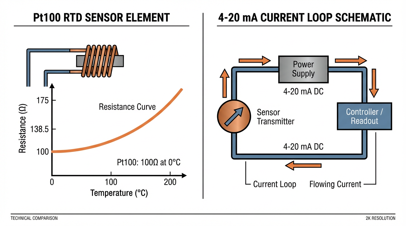
On the sensing side, you typically have a Pt100 RTD element. As Andivi explains, this is a platinum resistor that measures 100 Ohm at 0 °C, with resistance increasing in a predictable way as temperature rises. Industrial Pt100 probes are commonly built for ranges on the order of about -58 to 752 °F, depending on sensor class and construction.
On the transmission side, you have a 4-20 mA current loop. Fluke and other instrumentation vendors describe this as a DC‑powered series circuit where a transmitter converts the measured variable into a current between 4 and 20 mA. The lower end of the range, 4 mA, corresponds to the minimum temperature of interest, and 20 mA corresponds to the maximum. Current flows through the loop wiring, the input burden in your PLC or indicator, and often a precision shunt resistor.
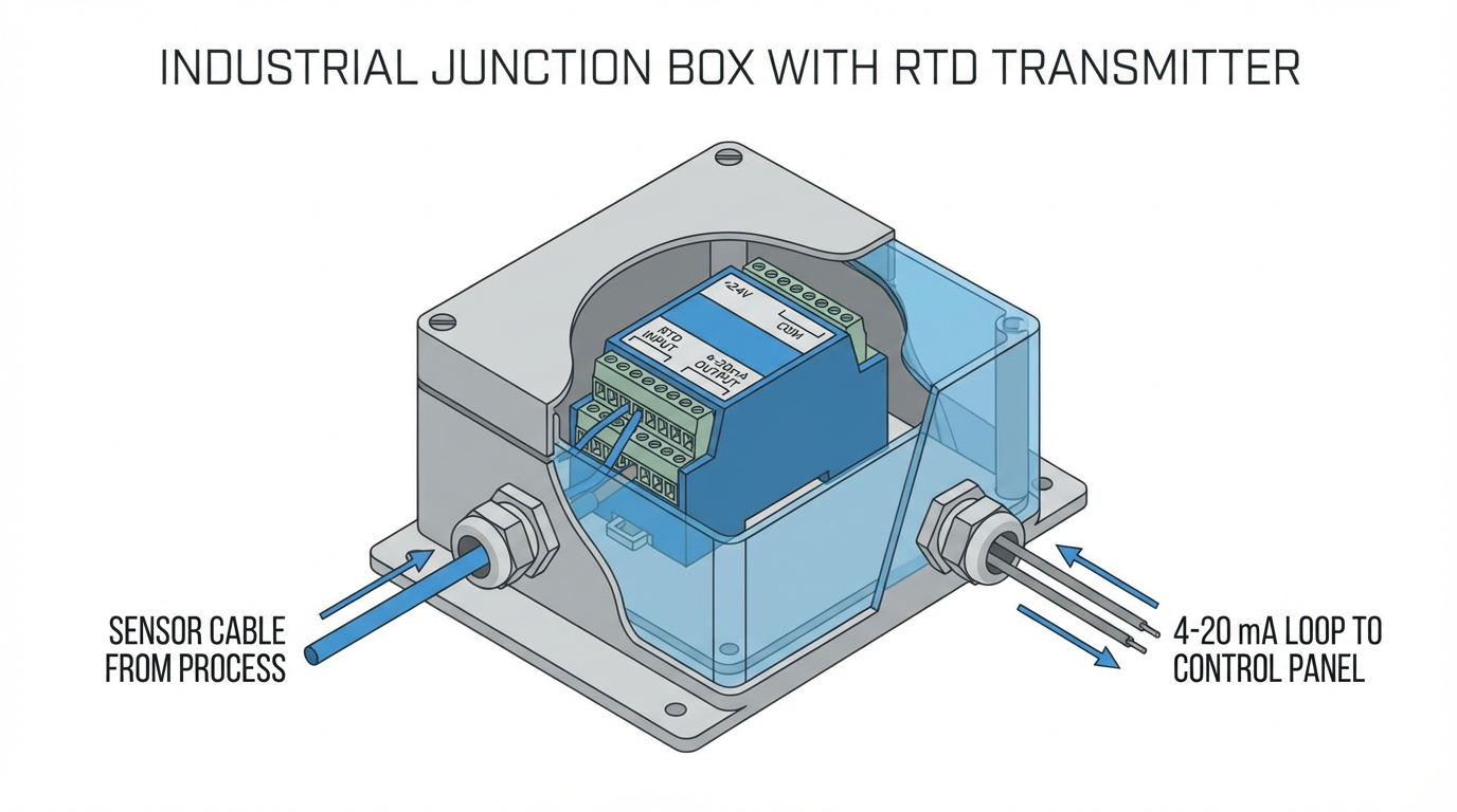
The RTD input module sits at the point where those two worlds meet. It measures the RTD’s resistance, converts that measurement into temperature in engineering units, then modulates loop current so that 4 to 20 mA represents the chosen temperature span. In practice the architecture looks like this in the field:
An RTD probe leaves the process and terminates either in a head‑mount transmitter on the sensor body, or in a remote DIN‑rail module in a nearby junction box or control panel. That transmitter drives a two‑wire or three‑wire 4-20 mA loop back to PLC analog input cards, panel displays, or both.
Predig and Fluke both emphasize that the same pattern repeats across process variables: temperature, level, pressure, and flow, but here we focus on temperature.
RTDs and 4-20 mA in Plain Language
It helps to be clear about what is a sensor and what is a signal type.
A Pt100 RTD is a sensing element. It does not speak 4-20 mA by itself. It simply changes resistance with temperature in a well defined, nearly linear way. Andivi notes that a Pt100 shows about 100 Ohm at freezing and a higher resistance at elevated temperatures, with industrial‑class devices achieving roughly plus or minus a few tenths of a degree Celsius under controlled conditions. Translated to Fahrenheit, that is on the order of about plus or minus 0.2 to 0.5 °F for quality industrial probes.
A 4-20 mA loop, by contrast, is a transmission method. Fluke and Control.com describe it as the dominant analog standard in industrial instrumentation. In a standard loop, 4 mA represents zero percent of the measurement span and 20 mA represents 100 percent. That 16 mA span carries the information.
In many “temperature transmitters” or ambient temperature modules, the two are combined. Andivi points out that the device you buy as a “4-20 mA temperature sensor” is usually a Pt100 element plus electronics that convert its resistance into a 4-20 mA signal. Comet’s outdoor and indoor ambient temperature transmitter is a good example: it measures local air temperature and outputs a two‑wire 4-20 mA signal in a watertight housing, with a configurable range and an integral display.
For control systems, this combination is powerful.
Many PLCs and building controllers have robust 4-20 mA analog inputs but limited or no dedicated RTD inputs. By using an RTD input, 4-20 mA output module, you can leverage standard current‑loop analog cards rather than specialized RTD modules.
Why Convert RTD Signals to 4-20 mA?
Direct RTD inputs to PLC analog cards look attractive on paper. You avoid extra hardware and you are measuring resistance directly. In practice, as Prelectronics points out, the accuracy of direct RTD or thermocouple inputs is often worse than expected once you install them in a real industrial environment. There are several reasons integrators still prefer RTD‑to‑4-20 mA conversion in most field applications.
Noise immunity and EMI in the real world
Thermocouples and RTDs generate very small electrical signals. Prelectronics notes that typical thermocouples create less than 50 mV and have almost no current‑drive capability. RTD sense wires carry only tiny currents, around a few tenths of a milliamp or less, and in three‑wire or four‑wire configurations the sense leads see virtually no current. In practice those long, lightly loaded wires behave like antennas.
Prelectronics lists the familiar culprits: 50 or 60 Hz mains fields, lightning, static discharges, handheld radios, commutator noise from DC motors, and variable‑frequency drives. With long sensor runs, especially in cable trays alongside power feeders, that noise couples easily into low‑level RTD and thermocouple signals.
The symptoms are the ones many of us have seen on site. Temperature readings jump whenever a nearby motor or heater starts, drift when a process section switches on or off, spike when a handheld radio transmits, or wander with time of day and weather. In some cases, simply moving a sensor cable changes the reading.

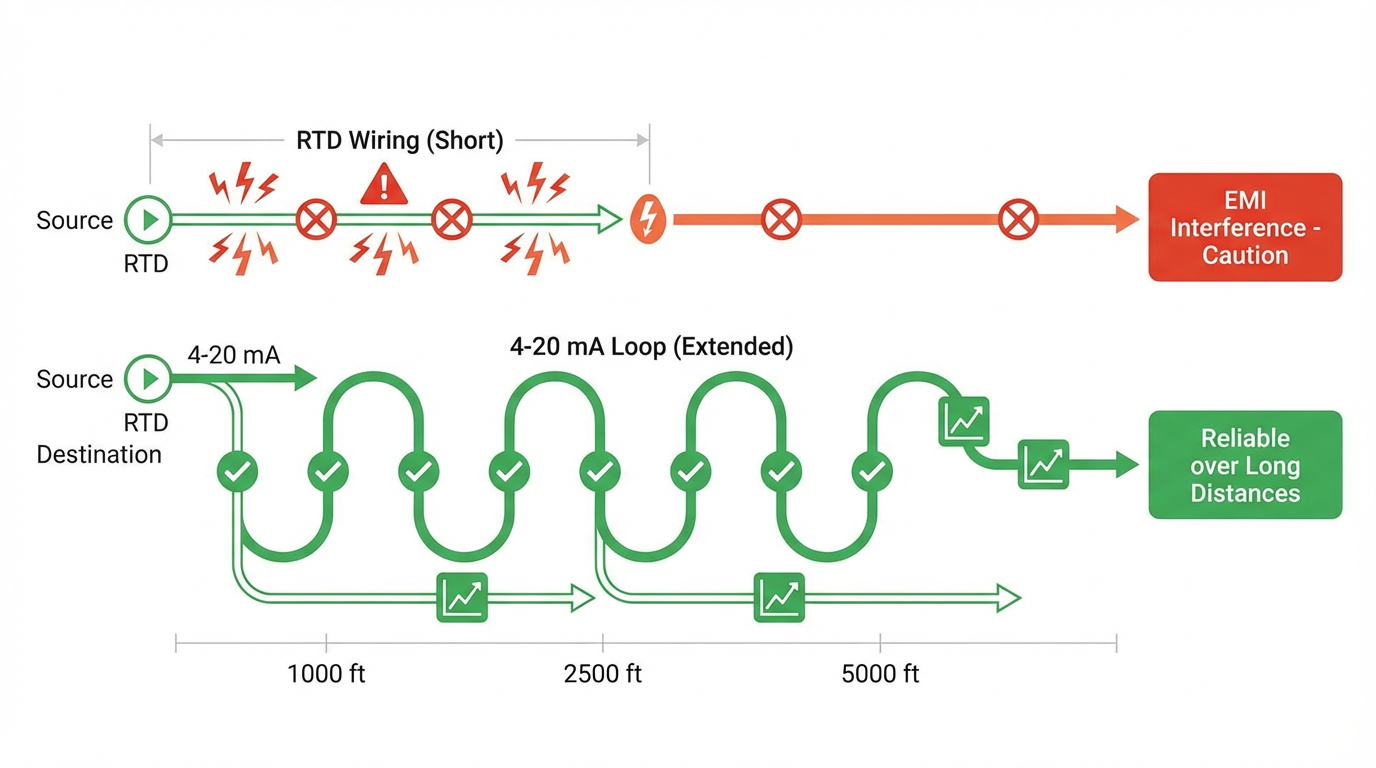
The remedy described by Prelectronics is to move the sensitive measurement as close as practical to the sensor, then convert to a robust 4-20 mA current. Once you convert to a current loop, the signal behaves very differently. A 4-20 mA loop carries the same current in both conductors but in opposite directions. EMI that happens to aid current in one conductor tends to oppose it in the other. The net loop current changes very little. Twisting the pair of loop conductors reinforces this effect by exposing both wires equally to induced fields and creating many small magnetic fields that oppose each other along the cable. As a result, a 4-20 mA loop can pass through areas of significant EMI with minimal disturbance.
Prelectronics also calls out cases where the field wiring is acceptable but the control panel itself is electrically noisy because of variable‑frequency drives, SCR controllers, soft starters, and DC drives. In these cases a DIN‑rail temperature transmitter inside the panel can convert low‑level RTD signals to 4-20 mA and provide galvanic isolation, dramatically reducing common‑mode noise.
Long distance and cable reuse
Fluke, Ashcroft, and Control.com all emphasize another key advantage: current loops tolerate long cable runs far better than voltage or direct resistance measurements. Because the same current flows through all series elements, moderate changes in wiring resistance have little effect as long as the loop power supply can still drive 20 mA through the total loop resistance.
Ashcroft notes that with appropriate loop design, 4-20 mA signals can be transmitted reliably over several thousand feet of cable.
SensorsOne points out that current loops do not suffer the same voltage‑drop‑induced errors as 0-10 V signals, and that they remain largely unaffected by moderate changes in load impedance or supply voltage.
Real‑world projects reflect this. In a multi‑zone floor heating system discussed on AutomationDirect’s forum, the designer wanted to reuse existing two‑conductor thermostat cabling from each room to a PLC cabinet. The chosen architecture was to install an RTD at each location, pair it with a low‑cost Pt100 transmitter configured for roughly -58 to 122 °F, and send a 4-20 mA signal back to the PLC over the existing wiring. RTD‑to‑current conversion at the wall sensor location turned aging thermostat cable into a viable industrial signaling medium without depending on a home‑automation server for the core control loop.
Live zero and fault detection
Control.com and Fluke explain that one of the reasons 4-20 mA became the dominant standard over an older 0-20 mA scheme is the “live zero” at 4 mA. When 0 mA and 0 percent of span are the same thing, a controller or PLC cannot tell a valid zero reading from a broken wire or dead transmitter. By raising the lower measurement limit to 4 mA, any reading near 0 mA can be treated as a fault.
Temperature transmitter vendors echo this. The bcstvalve article on temperature transmitters highlights that a current below 4 mA is used as an alarm condition to flag wiring problems, reducing downtime and improving overall system reliability. Some designs, as described in a general overview from Zeroinstrument, even reserve slightly below 4 mA and slightly above 20 mA to signal diagnostic conditions according to conventions such as NAMUR‑style fault currents.
For operators and maintenance, that behavior is extremely helpful.

A PLC can be configured so that 4 mA is the lowest valid temperature, while any value near 0 mA sets an alarm and marks the measurement as bad, triggering fallback strategies instead of quietly driving a loop based on nonsense.
Simplicity, compatibility, and visibility
A recurring theme in articles from Fluke, Predig, Microframe, and SensorsOne is that 4-20 mA remains popular because it is simple to design, easy to troubleshoot, and compatible with a wide range of equipment. Many PLC and DCS analog cards are designed to accept 4-20 mA directly, and if not, an external precision resistor can convert 4-20 mA to 1-5 V or similar spans that match standard voltage inputs.
Microframe describes how their analog‑input LED displays tap into 4-20 mA loops, convert them into large, easy‑to‑read numbers, and present process variables such as temperature or tank levels in plant areas where operators need immediate visibility. Because the display input represents only another loop burden, it can often be added without re‑engineering the entire system.
In short, converting RTD signals to 4-20 mA aligns with installed infrastructure, plant standards, and the skill set of technicians who already carry loop calibrators and handheld multimeters.
Inside an RTD Input, 4-20 mA Output Module
Although every manufacturer has its own implementation, the internal architecture of an RTD input, 4-20 mA output module follows a common pattern.
Front end: measuring the RTD accurately
The first task is to measure the RTD’s resistance accurately while compensating for lead resistance. Andivi notes that Pt100 sensors can be wired with two, three, or four wires. Three‑wire and four‑wire schemes are used to compensate for the resistance of the cable itself, which would otherwise add error. Prelectronics points out that in three‑ and four‑wire RTDs, the sense wires carry virtually no current, which is part of why they are so susceptible to EMI when run long distances.
In a typical module, a constant, very small excitation current flows through the RTD element, and the resulting voltage drop is measured by an internal amplifier and analog‑to‑digital converter.
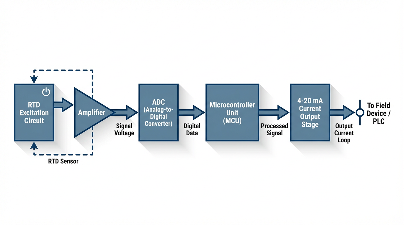
The module’s firmware then converts that resistance value into temperature based on the RTD curve.
An Analog Devices design note illustrates a similar concept for a semiconductor sensor: a temperature sensor with a known millivolt‑per‑degree scale factor feeds an operational amplifier and a resistor that sets the current scale. The analog principle is the same when the source is an RTD rather than a silicon sensor: convert temperature‑dependent voltage into a proportional loop current.
Scaling temperature into 4-20 mA
Once the temperature is known in engineering units, the module needs to map that temperature onto the 4-20 mA range. Several of the research notes walk through explicit examples.
In a MeteoDrenthe project, an off‑the‑shelf Pt100 transmitter was ordered with a default range of about -58 to 212 °F and then reconfigured, using the manufacturer’s software, to a more practical outdoor range of about -22 to 113 °F. The transmitter was set so that 4 mA represented the low temperature and 20 mA the high temperature, with a linear interpolation in between.
Electronics Stack Exchange contributors describe the generic math behind this: treat the 16 mA span between 4 and 20 mA as the full engineering span between minimum and maximum temperature. Once you know the loop current, you can calculate where you are between 4 and 20 mA and map that proportionally into degrees Fahrenheit.
That linear relationship is what makes 4-20 mA so straightforward. Whether your input module is loop‑powered or has an external supply, inside it will drive a loop current based on a simple linear transform of the measured temperature.
Loop powering: 2‑wire, 3‑wire, and 4‑wire options
Ashcroft and The Transmitter Shop both describe the common loop power configurations.
In a two‑wire, or loop‑powered, design, the module takes both its operating power and the measurement signal from the same two conductors that form the loop. The transmitter acts as a controlled current sink, “stealing” a small amount of voltage from the loop to power its electronics while modulating the current between 4 and 20 mA. This is the most common configuration for compact temperature transmitters and ambient probes such as Comet’s T0110. It minimizes wiring and simplifies field installation.
In a three‑wire design, two wires provide DC power (for example plus 24 V and common), and a third wire carries the 4-20 mA signal referenced to that common. As Ashcroft and The Transmitter Shop note, this arrangement gives the electronics more power headroom for features such as local displays, keypads, or more intensive diagnostics while keeping the signal path separate from the main power conductors.
In a four‑wire transmitter, two wires provide an independent power source, which can be AC or DC, and two separate wires carry the isolated 4-20 mA signal.
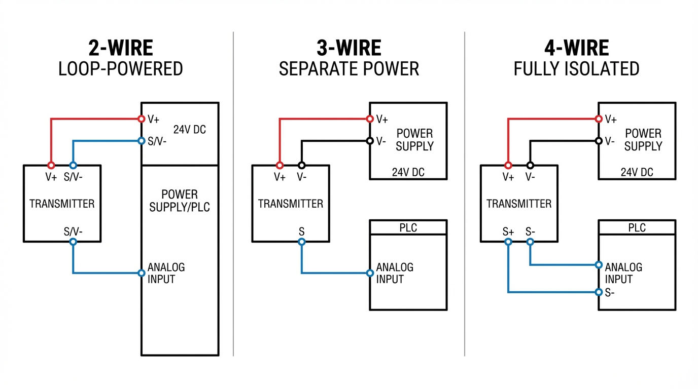
The Transmitter Shop emphasizes that this complete separation provides the highest level of isolation and noise immunity and effectively eliminates ground loop issues. Four‑wire designs are typically reserved for analytical instruments or transmitters with heaters or more complex internal processing, where power demand and the need for isolation justify the extra wiring.
The RTD input modules used in temperature systems are often two‑wire loop‑powered devices for field mounting, with three‑wire or four‑wire transmitters used where displays, advanced diagnostics, or isolation requirements justify them.
Accuracy, ADC resolution, and component quality
The mapping from RTD resistance to loop current is only as good as the components and converters behind it. The MeteoDrenthe project is instructive here. When the author read an RTD directly using a generic interface board, the system required relatively large calibration offsets. Switching to an original, higher‑quality board reduced the required offset dramatically. Later, when they moved to a 4-20 mA Pt100 transmitter, the internal measurement of the transmitter calibrated very close to freezing in an ice bath, while the overall system accuracy still depended on the precision of the shunt resistor and the external analog‑to‑digital converter.
Resistor tolerance is a major contributor. In that project, a 165 Ohm resistor was selected to convert 4-20 mA into about 0.66 to 3.3 V for a 3.3 V microcontroller analog input. A cheap five percent resistor would have allowed the actual value to drift over a wide range, introducing several degrees of temperature uncertainty. Moving to a 0.1 percent precision resistor reduced that contribution to well under a degree Celsius, which corresponds to well under a degree Fahrenheit of potential error.
ADC resolution is the other side of the coin. The on‑board 10‑bit ADC in the microcontroller yielded temperature steps of about a few hundredths of a degree Celsius over the chosen span, which the author considered marginal for the precision they wanted. Switching to an external 16‑bit ADC (an ADS1115) provided far finer resolution.

The author also discovered that inexpensive ADC “clones” sometimes behaved like lower‑resolution devices, underscoring the value of genuine components in precision temperature applications.
In a pure industrial module, those design decisions are hidden from the integrator, but the same principles apply. Vendors such as Prelectronics explicitly highlight the benefits of high‑quality transmitters with isolation, linearization, and filtering to deliver accurate and repeatable 4-20 mA temperature signals even in EMI‑heavy environments.
Practical Design Guidance for Integrators
From an integrator’s perspective, there are a few recurring decisions every time you specify RTD input, 4-20 mA output modules on a project.
Decide where to convert: at the sensor, in the panel, or both
Prelectronics outlines two practical locations for conversion: at the sensor and in the panel. Mounting a transmitter on the RTD head or in a nearby junction box keeps RTD lead lengths very short, which minimizes their exposure to EMI and removes the need to run delicate sensor wiring through cable trays or across building structures. From that point forward, you enjoy the robustness of a 4-20 mA loop.
When rerouting or replacing field wiring is difficult, a panel‑mounted DIN‑rail transmitter can still help. It takes in the low‑level RTD signal on a short run inside the panel, converts it to 4-20 mA with isolation, and feeds a PLC analog input card. This approach is especially valuable when EMI inside the panel is the main issue, for example when several drives and soft starters share the same enclosure.
In high‑value or high‑noise applications, Prelectronics describes the use of two transmitters: one at the sensor to convert to 4-20 mA and a second in the panel to provide isolation, signal splitting, added diagnostics, and local display. This configuration minimizes sensor lead length, maximizes immunity to EMI, and provides flexibility to feed the same temperature to multiple PLCs, indicators, or safety systems.
Size and verify the 4-20 mA loop
Fluke, Seametrics, and AutomationDirect all stress that a current loop has to be treated as a complete series circuit that obeys Ohm’s law. The loop power supply must provide enough voltage to drive 20 mA through the total loop resistance, which includes wiring, analog input burdens, shunt resistors, and the internal voltage drop of the transmitter itself.
Design notes typically recommend checking that the total loop resistance stays below a value calculated as the available supply voltage minus the transmitter’s minimum operating voltage, divided by 20 mA. Practitioners often use 24 V DC supplies because they provide comfortable headroom. Many transmitters are designed to operate over a wide compliance range; Analog Devices, for example, describes a loop‑powered temperature circuit that runs from around 3.75 to 28 V.
AutomationDirect’s troubleshooting guide gives a practical field method to confirm the transmitter output with basic tools. Disconnect the transmitter’s signal lead from the PLC, place a precision 250 Ohm resistor between the signal and the loop return, and measure the voltage across the resistor with a multimeter. At 4 mA you should see about 1 V, at mid‑span about 2.5 V, and at 20 mA about 5 V. If the voltage range matches expectations, the transmitter and its loop are healthy, and attention should shift to the PLC input scaling or wiring.
The same article describes a quick test for the PLC analog input card itself: drive it with a simple current generated by a 1.5 V battery in series with a 250 Ohm resistor. That combination produces around 6 mA, which corresponds to roughly one eighth of the 4-20 mA span. If the PLC input does not register a value in the expected region when driven by this known current, the issue is likely in the wiring or the module configuration.
Interfacing loops to PLCs, DAQs, and microcontrollers
PLC and DCS analog input cards designed for 4-20 mA often include an internal burden resistor and handle current directly. In other cases, especially with microcontrollers or small DAQs, you measure the loop voltage across an external resistor.
Several sources converge on practical resistor values. A 250 Ohm resistor converts 4-20 mA into roughly 1-5 V, a range commonly expected by industrial analog inputs. This is the value AutomationDirect and many 4-20 mA primers use in their examples. In a low‑voltage microcontroller system, as in the MeteoDrenthe project, a 165 Ohm resistor converted 4-20 mA into about 0.66 to 3.3 V, staying within a 3.3 V ADC range. In a Duet3D controller scenario, a 150 Ohm resistor provided about 0.6 to 3.0 V for an analog input.
Community discussions on Arduino and Electronics Stack Exchange underline two practical points. First, you must ensure that the sensor or transmitter has the required supply voltage. One Arduino forum case involved a 4-20 mA sensor that needed at least 15 V DC; powering it from a 5 V microcontroller rail simply could not work. Second, while the math is straightforward, you should not assume scaling parameters; always confirm the specified temperature range that 4 and 20 mA represent from the transmitter’s datasheet and then verify with known temperatures.
For safety and isolation, the Duet3D example also warns that when the 4-20 mA device’s output ground is not common with the control system ground, you may need an isolated ADC or a floating power supply to avoid ground loops or damage. That is another reason industrial RTD‑to‑4-20 mA modules with built‑in isolation are attractive for PLC‑level systems.
Using displays and auxiliary outputs
Once you have a clean 4-20 mA temperature loop, additional visibility is easy to provide. Microframe shows how analog‑input LED displays can mirror existing loops without significantly loading them, giving operators and maintenance staff large, readable temperature values in key locations. Prelectronics notes that panel‑mounted transmitters can offer backlit displays that show process values, relay status, and sensor or loop errors, as well as signal splitting to provide multiple isolated 4-20 mA outputs from a single RTD input.
These features are not strictly necessary for control, but they are often the difference between a system that operators trust and one they bypass whenever they can.
Comparing Architectures: Direct RTD vs RTD + 4-20 mA Module
The tradeoffs between wiring RTDs directly into a PLC and using RTD input, 4-20 mA output modules can be summarized concisely.
| Aspect | Direct RTD into PLC | RTD Input, 4-20 mA Output Module |
|---|---|---|
| Noise immunity | Low for long sensor runs; RTD and thermocouple leads behave like antennas in EMI, as highlighted by Prelectronics | High; current loops are strongly resistant to EMI, especially with twisted pairs and proper routing |
| Cable length | Best for short, clean runs; long cables require careful shielding and routing | Well suited for long runs; Fluke and Ashcroft note reliable operation over thousands of feet when loop design is correct |
| Wiring and modules | Requires PLC cards with dedicated RTD inputs and careful 2-, 3-, or 4‑wire terminations | Uses standard 4-20 mA analog inputs; RTD wiring is short and local to the transmitter |
| Fault detection | Requires logic to detect open or shorted RTDs; failures can be ambiguous | Live zero at 4 mA means near‑zero current is a clear fault; diagnostic ranges below 4 mA or above 20 mA can signal specific errors |
| EMI inside panels | Low‑level RTD signals are vulnerable to noise from drives and power electronics | Properly isolated transmitters largely eliminate common‑mode noise and panel EMI issues |
| Flexibility and visibility | Harder to split signals or add displays without extra modules | Panel transmitters and displays can split and mirror signals to multiple PLCs and large indicators |
For most industrial environments with any significant distance or electrical noise, the RTD‑plus‑transmitter architecture is the safer and more maintainable choice.
Direct RTD connections tend to make sense only where distances are short, EMI is well controlled, and the highest possible intrinsic accuracy justifies more careful wiring and specialized PLC I/O.
Advantages and Tradeoffs of 4-20 mA Temperature Modules
The SensorsOne overview on 4-20 mA advantages and disadvantages matches what most of us see in practice.
On the positive side, 4-20 mA signals can be run over long distances with minimal signal loss, they are rugged and have low susceptibility to electromagnetic interference, and they only require two wires in a loop‑powered configuration. The live zero at 4 mA serves as a built‑in electrical health indicator: if the loop current collapses toward 0 mA, you likely have a wiring issue or a failed transmitter, not a valid process zero. Fluke and Predig both stress the simplicity of designing, commissioning, and troubleshooting current loops with ordinary multimeters and loop calibrators.
On the tradeoff side, SensorsOne notes that current loops do consume more power than some other analog methods. There is also the conceptual nuance that zero reading corresponds to 4 mA rather than 0 mA, which must be handled in PLC scaling and operator training. As total loop resistance increases with longer cables or additional devices, the voltage available to power the transmitter falls; this limits how many loads you can put in series and ultimately constrains loop length for a given supply.
In temperature measurement, those tradeoffs are usually acceptable. Loop power consumption is modest relative to other industrial loads, and the benefits in robustness and diagnostics outweigh the complexity of scaling 4-20 mA into engineering units.
Brief FAQ
How do I choose the temperature range for an RTD input, 4-20 mA output module?
Start from the real operating conditions rather than the extreme rating of the sensor. In the MeteoDrenthe project, a Pt100 transmitter shipped with a default range around -58 to 212 °F, but the author reconfigured it to cover a narrower outdoor range of about -22 to 113 °F. That tighter span gave better effective resolution and made better use of the 16 mA current span. Many transmitters, like those discussed by Prelectronics and Comet, can be configured over a wide range using vendor software and a USB interface. Always confirm that the PLC or controller scaling matches the configured range so that 4 mA and 20 mA convert to the intended temperatures.
What loop configuration should I use: 2‑wire, 3‑wire, or 4‑wire?
For most simple temperature loops where the transmitter does not need much power, a two‑wire loop‑powered module is ideal. It keeps wiring simple and leverages the inherent noise robustness of 4-20 mA. As Ashcroft and The Transmitter Shop explain, if your transmitter requires more power for a large display, advanced diagnostics, or internal processing, a three‑wire configuration with separate power and signal conductors gives you extra headroom. Four‑wire transmitters, with fully isolated power and signal pairs, are best reserved for demanding analytical instruments or very noisy environments where eliminating ground loops is critical.
How do I verify that a temperature loop is actually working?
AutomationDirect’s troubleshooting note provides a practical method that does not require exotic tools. First, confirm that the transmitter has its specified supply voltage and that loop polarity is correct. Next, temporarily disconnect the PLC input and place a precision resistor, often 250 Ohm, across the loop. Measure the voltage across that resistor at different process conditions; 4-20 mA should translate to roughly 1-5 V. If the transmitter passes this test, inject a known current into the PLC input using a small battery and resistor, as described earlier, and verify that the PLC registers the expected scaled value. This approach isolates transmitter and PLC issues without guessing.
Closing Thoughts
RTD input, 4-20 mA output modules are not glamorous pieces of hardware, but when you are responsible for keeping a plant running, their behavior matters more than their marketing. The combination of a precise Pt100 sensor with a well‑designed current‑loop transmitter gives you stable, diagnosable temperature signals over long distances and through heavy electrical noise, using infrastructure and skills that every industrial maintenance team already has.
If you treat each loop as a complete system, pay attention to EMI, loop resistance, and scaling, and choose the right two‑wire, three‑wire, or four‑wire architecture for the job, these modules will give you years of trouble‑free service. That is why, project after project, they remain one of the most reliable tools in a temperature integrator’s toolbox.
References
- https://www.plctalk.net/forums/threads/how-to-get-scaled-4-20ma-temperature-sensor-signal-in-plc.117376/
- https://blog.ashcroft.com/two-wire-loop-powered-transmitter
- https://microframecorp.com/Using-4%E2%80%9320-mA-Analog-Signals-for-Display-Control-%E2%80%94-What-You-Need-to-Know_b_30.html?srsltid=AfmBOopwIfgIjwwUgMwo6w1JFqD7bEDqcd8pzA-vdpPggLCSgycNoiAj
- https://www.andivi.com/whats-the-difference-between-4-20-ma-and-pt100-sensors/
- https://library.automationdirect.com/4-20ma-analog-transmitter-troubleshooting/
- http://bcstvalve.com/why-the-temperature-transmitter-4-20ma-is-the-best-choice-for-reliable-signal-transmission/
- https://www.predig.com/indicatorpage/back-basics-fundamentals-4-20-ma-current-loops?srsltid=AfmBOoqB6W2432ZwJQTTW_6KUEQuh15ZG_SI9WtesIN4RlSBI5bTQg17
- https://www.sensorsone.com/4-20ma-use-advantages-disadvantages/
- https://zeroinstrument.com/why-is-the-4-20ma-signal-used-for-instrumentation-transmission/
- https://forum.arduino.cc/t/how-can-i-conect-a-4-20-ma-sensor-with-external-electrical-supply/245992
Keep your system in play!
Top Media Coverage
Categories


Related articles Browse All
-
 amikong NewsSchneider Electric HMIGTO5310: A Powerful Touchscreen Panel for Industrial Automation2025-08-11 16:24:25Overview of the Schneider Electric HMIGTO5310 The Schneider Electric HMIGTO5310 is a high-performance Magelis GTO touchscreen panel designed for industrial automation and infrastructure applications. With a 10.4" TFT LCD display and 640 x 480 VGA resolution, this HMI delivers crisp, clear visu...
 -
 BlogImplementing Vision Systems for Industrial Robots: Enhancing Precision and Automation2025-08-12 11:26:54Industrial robots gain powerful new abilities through vision systems. These systems give robots the sense of sight, so they can understand and react to what is around them. So, robots can perform complex tasks with greater accuracy and flexibility. Automation in manufacturing reaches a new level of ...
 -
 BlogOptimizing PM Schedules Data-Driven Approaches to Preventative Maintenance2025-08-21 18:08:33Moving away from fixed maintenance schedules is a significant operational shift. Companies now use data to guide their maintenance efforts. This change leads to greater efficiency and equipment reliability. The goal is to perform the right task at the right time, based on real information, not just ...


- Q&A
- Policies How to order Part status information Shipping Method Return Policy Warranty Policy Payment Terms
- Asset Recovery
- We Buy Your Equipment. Industry Cases Amikong News Technical Resources Why choose us
- ADDRESS
-
 32D UNITS,GUOMAO BUILDING,NO 388 HUBIN SOUTH ROAD,SIMING DISTRICT,XIAMEN
Leave Your Comment