
-
Please try to be as accurate as possible with your search.
-
We can quote you on 1000s of specialist parts, even if they are not listed on our website.
-
We can't find any results for “”.
ABB ACS880 Industrial Drive Manual: Installation and Commissioning Done Right
The ACS880 family is one of those drive platforms you see everywhere once you start looking. I have seen it on cranes, in paper mills, next to cooling towers, and buried in OEM machinery. When an ACS880 installation behaves, it quietly runs for years. When the installation or commissioning is sloppy, the same hardware becomes a source of nuisance trips, EMC headaches, and safety risk.
The official hardware and quick installation manuals from ABB are written to prevent exactly that. This article walks through how to use those manuals effectively when installing and commissioning ACS880 industrial drives, with a focus on practical field practice rather than theory. It does not replace the ABB documentation; instead it explains how a systems integrator should apply it on the floor.
Why The Hardware Manual Matters More Than The Datasheet
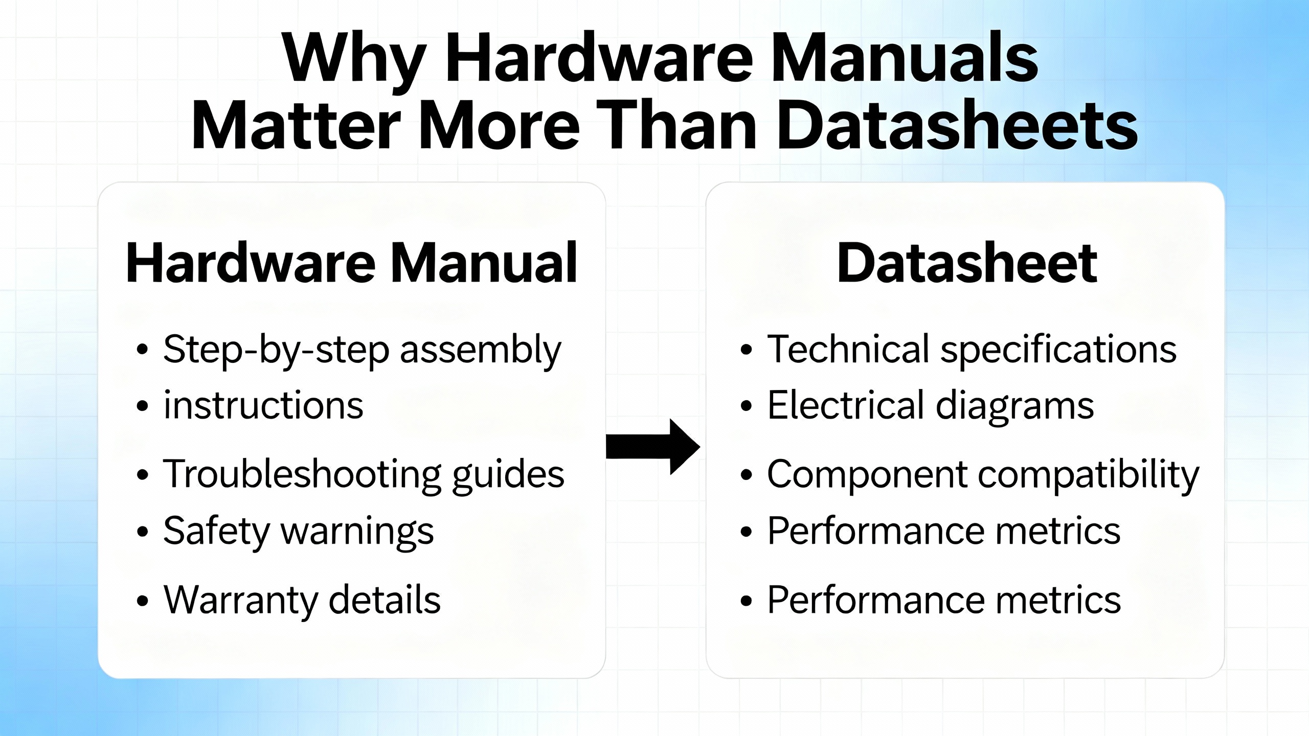
In the ACS880 documentation set the hardware manual and quick guides do the unglamorous work. They define frame dimensions, clearances, torque values for terminals, cable types, derating rules, and maintenance tasks. They also capture safety definitions such as DANGER, WARNING, and CAUTION, and make it explicit that only qualified electricians are allowed inside the drive.
ABB’s ACS880 hardware manuals and quick installation guides consistently cover:
Product identification and type codes so you know exactly which variant you have, for example ACS880-01 single drives or ACS880-11 ultra‑low‑harmonic modules. Ratings and technical data by frame size, including nominal supply voltages, output currents, and short‑circuit withstand levels. Mechanical dimensions and mounting requirements. Terminal layouts and recommended wiring practices for mains, motor, braking or regenerative connections, control I/O, and communication options. Environmental and EMC requirements: ambient temperature limits, altitude derating, humidity, pollution degree, vibration limits, and EMC‑compliant cabling and grounding. Routine inspection, cleaning, and component replacement.
In other words, the manual is the engineering basis for your panel layout, protection coordination, and commissioning checklist. If you size breakers from a brochure and guess clearances, you are accepting avoidable risk.
Safety First: How ABB Structures Warnings And What They Mean In Practice
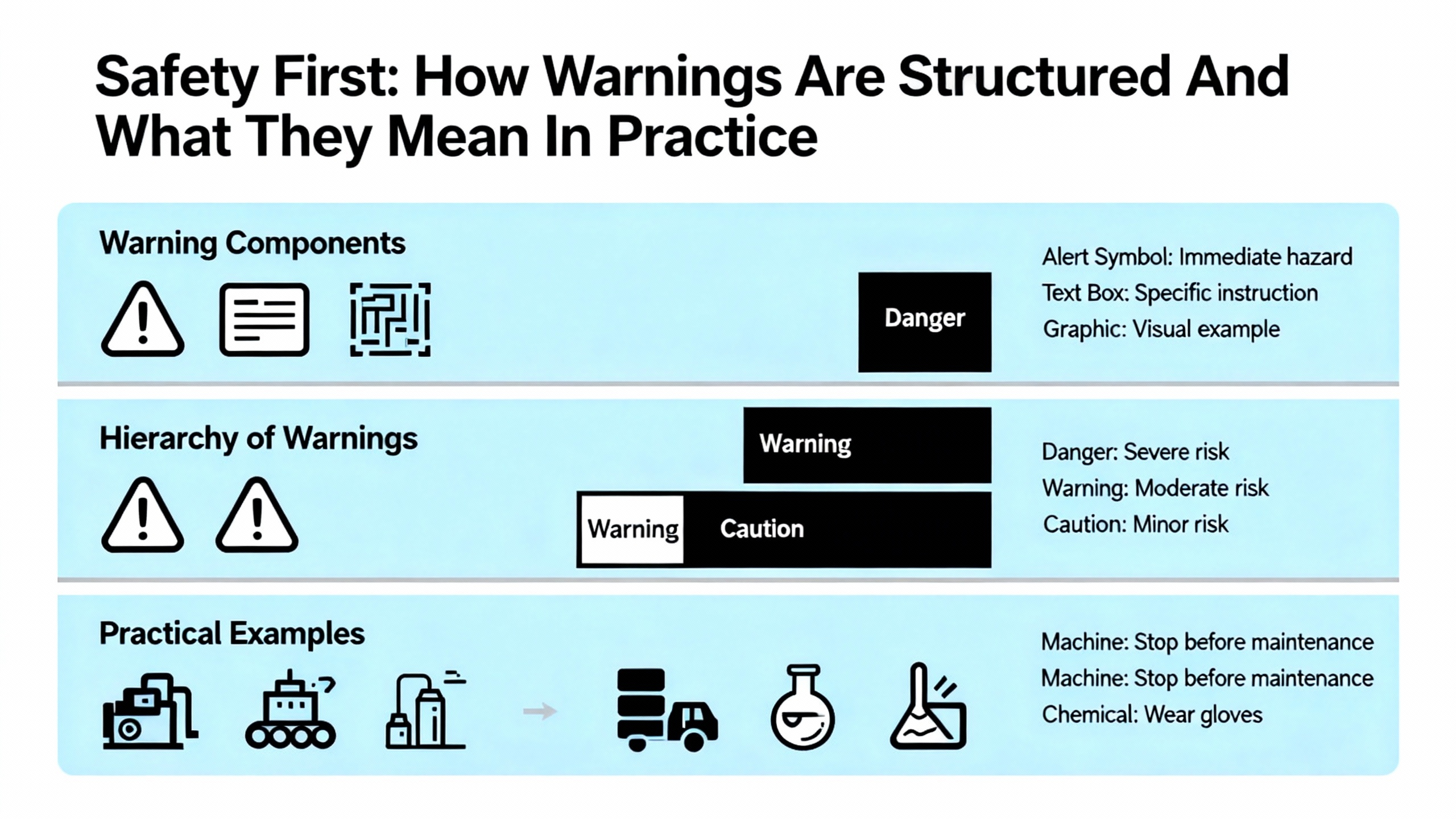
ABB uses standardized safety signal words across ACS880 hardware documents. DANGER indicates a hazardous situation that will result in serious injury or death if not avoided, typically associated with live parts or rotating machinery. WARNING indicates a risk that could cause injury or major equipment damage. CAUTION is used for hazards that may cause minor injury or equipment damage. NOTE is reserved for important guidance that improves reliability or usability.
In practical terms, the safety section of the manual is non‑negotiable. It assumes a few things that must be true before you start:
Only trained personnel with responsibility for industrial electrical systems are installing or servicing the drive. Lockout‑tagout procedures are in place, not just a verbal “it’s off.” The supply is isolated on all phases, and you wait the specified DC bus discharge time before removing covers. You verify absence of voltage with appropriate instruments on mains, motor, and braking terminals. You treat the motor and any mechanically coupled load as potentially dangerous even when the drive is off; gravity and stored mechanical energy ignore your assumptions.
The manuals also stress appropriate personal protective equipment and compliance with local electrical regulations and relevant IEC or UL standards. That might sound like boilerplate, but after you have seen one drive with a charred DC bus because someone defeated interlocks, you tend to take those pages seriously.
Understanding Your ACS880 Variant And The Document Set
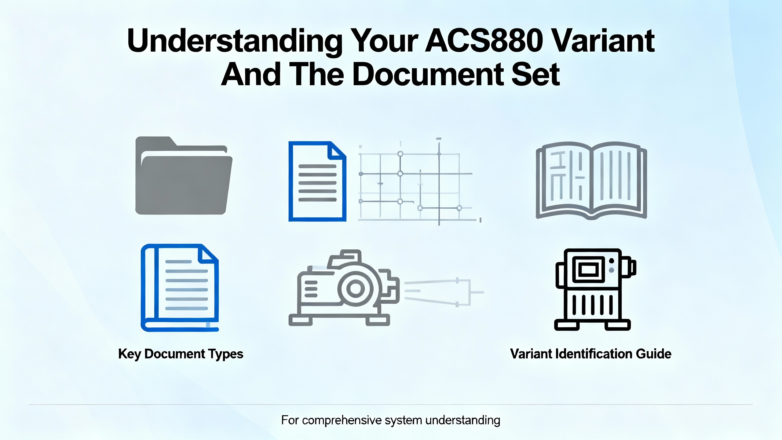
One recurring headache on projects is confusion between drive variants and their documentation. The ACS880 family includes single drives like ACS880‑01, ultra‑low‑harmonic modules such as ACS880‑11, regenerative or supply modules such as ACS880‑17, and various multi‑drive configurations. Each has its own hardware manual and quick installation or quick installation and safety guide.
A simplified view of the document set looks like this:
| Document type | Main focus | When you rely on it |
|---|---|---|
| Hardware manual (ACS880‑xx HW) | Mechanical design, wiring, ratings, cooling, maintenance, safety | Panel design, cable selection, protection coordination, servicing |
| Quick Installation Guide (QIG / QISG) | Essential mounting, wiring, and first start‑up steps | Onsite install where basic configuration is enough to run the motor |
| Firmware or control program manual | Parameters, control modes, application macros, diagnostics | Commissioning, tuning, troubleshooting, integration to controls |
| Option module manuals (fieldbus, I/O) | Pin‑outs, LEDs, configuration for each communication or I/O module | Network integration and advanced I/O schemes |
Before you start designing or wiring, match the type code on the drive nameplate to the exact manual revision. With ACS880‑11 and other specialized variants, using a generic ACS880 manual instead of the correct hardware document is an easy way to miss ULH‑specific or regenerative‑specific requirements.
Planning The Installation: Environment, Power System, And Layout
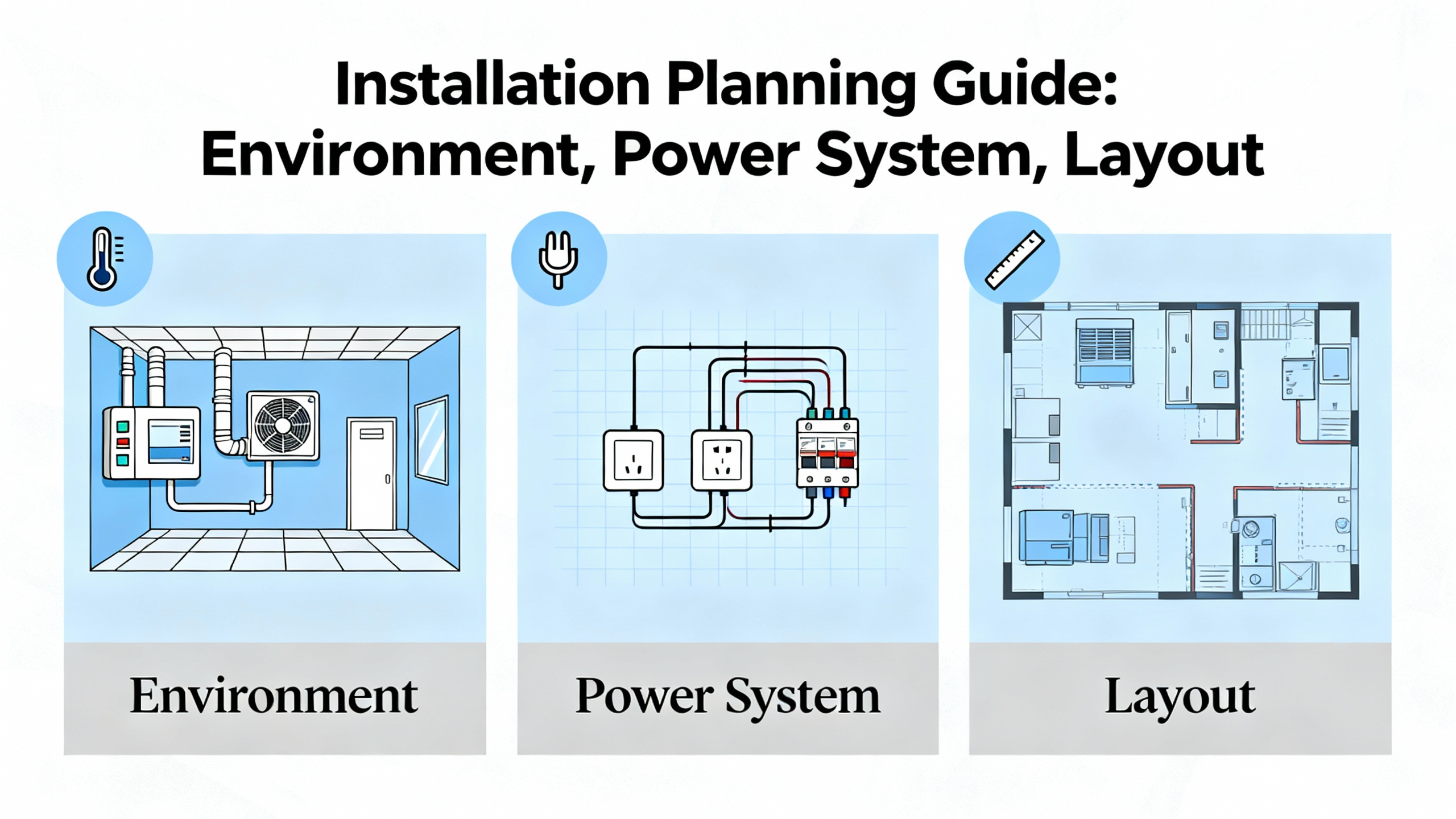
Good commissioning starts long before you hang a drive on a backplate. The hardware manual is explicit about where the product is allowed to live and what kind of power system it expects.
From an environmental perspective, ABB specifies acceptable ambient temperature bands, humidity, and pollution degree, and provides derating rules for higher temperatures and greater altitudes. In practice that means you design the enclosure so that internal air stays within the published Fahrenheit limits, not just the room temperature. Drives mounted in small, poorly ventilated panels near the roof of a hot plant will see much higher air temperatures than the operators do at floor level.
Altitude derating is equally easy to ignore until fans start running flat out. Above roughly three thousand feet, most ACS880 hardware manuals instruct you to reduce allowable current as air density drops. For installations in mountainous regions or tall buildings, you cannot treat nameplate current as a constant.
On the electrical side, the manuals assume a three‑phase industrial supply and define nominal voltage classes that, across the broader ACS880 family, span common low‑voltage levels. They also reference maximum permitted short‑circuit current at the point of common coupling. That number drives your selection of fuses or circuit breakers and informs whether additional protective devices, such as upstream reactors, make sense. ABB repeatedly advises selecting the drive and its protection based on motor current and duty cycle rather than nameplate kilowatts alone.
Mechanical Installation: Frames, Clearances, And Cooling
Physically mounting the ACS880 is more subtle than just “vertical on a wall,” although that is generally the required orientation. The hardware manuals lay out minimum free space above and below the unit for proper airflow, side‑to‑side clearances if you mount multiple frames in a lineup, and cabinet layout rules when the drive is used as a module inside a custom enclosure.
From field experience, two points matter most.
First, treat the cooling path as part of the design. If the manual calls for several inches of free space above the heatsink exhaust and recommends ducting hot air out of the cabinet, do not bury the drive under cable trays or push it tight to the top of a small panel. In cramped cabinets I have seen ACS880s that technically met the minimum clearances but still ran hot because the enclosure fans were undersized and airflow had no defined path.
Second, respect vibration and contamination limits. The hardware manuals specify acceptable vibration levels and pollution degree. If the drive is mounted on a structure that carries heavy mechanical shock, or in an area with conductive dust or corrosive gas, you must either relocate it or use an enclosure solution that meets the specified protection class. In practice that can mean moving drives out of the immediate process zone, using sealed cabinets with forced ventilation through filters, or adding vibration isolation.
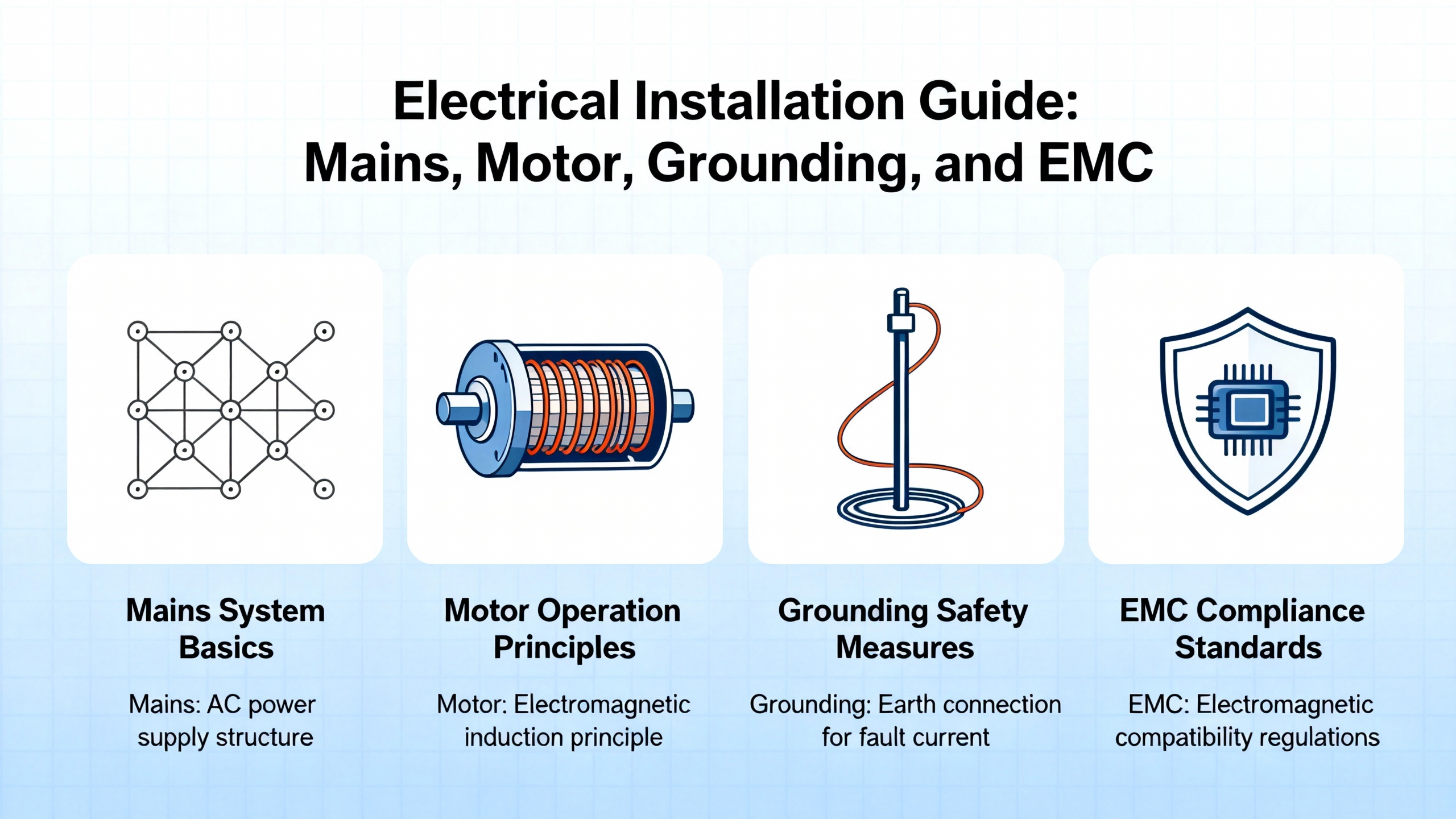
Electrical Installation: Mains, Motor, Grounding, And EMC
The electrical installation sections of ABB’s ACS880 manuals are dense for a reason. The decisions you make here determine not only whether the drive runs, but whether it coexists peacefully with the rest of the plant.
On the mains and motor side the manuals describe how to route and terminate incoming supply and motor cables, specify torque values for terminals, and give recommended protective device ratings. They emphasize using separate protective earth conductors with short, low‑impedance paths back to the main protective ground, and they warn against daisy‑chaining earths along a row of drives.
Segregation of cabling is particularly important. The hardware and quick installation guides repeatedly instruct you to keep motor and supply cables away from low‑level control and instrumentation wiring, to cross power and control conductors at right angles where they must intersect, and to avoid sharing conduits between high‑power and sensitive signal cables. If you run encoder, analog, and Ethernet cables through the same metallic conduit as motor leads on an ACS880 installation, you can expect intermittent faults and noisy feedback.
For EMC compliance the manuals usually recommend shielded motor and control cables, with the shields terminated using a 360‑degree clamp at the drive end and, in many cases, at the motor or control cabinet end as well. They also explain when and how to use built‑in EMC filters or external chokes depending on the supply system type, for example TN, TT, or IT networks in IEC terminology. In multi‑drive lineups or ULH applications like ACS880‑11, following those EMC instructions is the difference between passing and failing site acceptance testing with the local regulator.
Control And I/O: Getting Signals And Safety Right
ACS880 hardware documentation dedicates a fair amount of space to control terminals. You typically have digital inputs and outputs for start, stop, direction, interlocks, and ready or fault signals; analog inputs and outputs for speed, torque, or process references and feedback; relay contacts for run or fault indication; and connectors for encoder or resolver feedback. Optional fieldbus adapters add additional ports for networks such as Profibus, Profinet, EtherNet/IP, or other industrial Ethernet systems.
The manuals clarify default terminal functions, signal levels, and isolation boundaries. That is not just trivia. For example, if you repurpose a digital input without realizing it is part of the safe torque off (STO) chain, you can defeat a safety function or create a non‑obvious interlock that trips on every restart. Functional safety options, including STO and extended safety modules, are described in ABB literature as safety functions that must be wired and validated according to applicable functional safety standards. From a systems integrator’s perspective, that means the hardware manual, the safety option manual, and the machine’s safety concept all have to align.
Recommended wiring practices in the manuals include using twisted, shielded pairs for analog signals and encoder lines, keeping cable lengths within specified maxima, and terminating shields correctly. When those rules are ignored, I have seen drives that commission smoothly on day one but develop sporadic encoder loss faults whenever a nearby large motor starts.
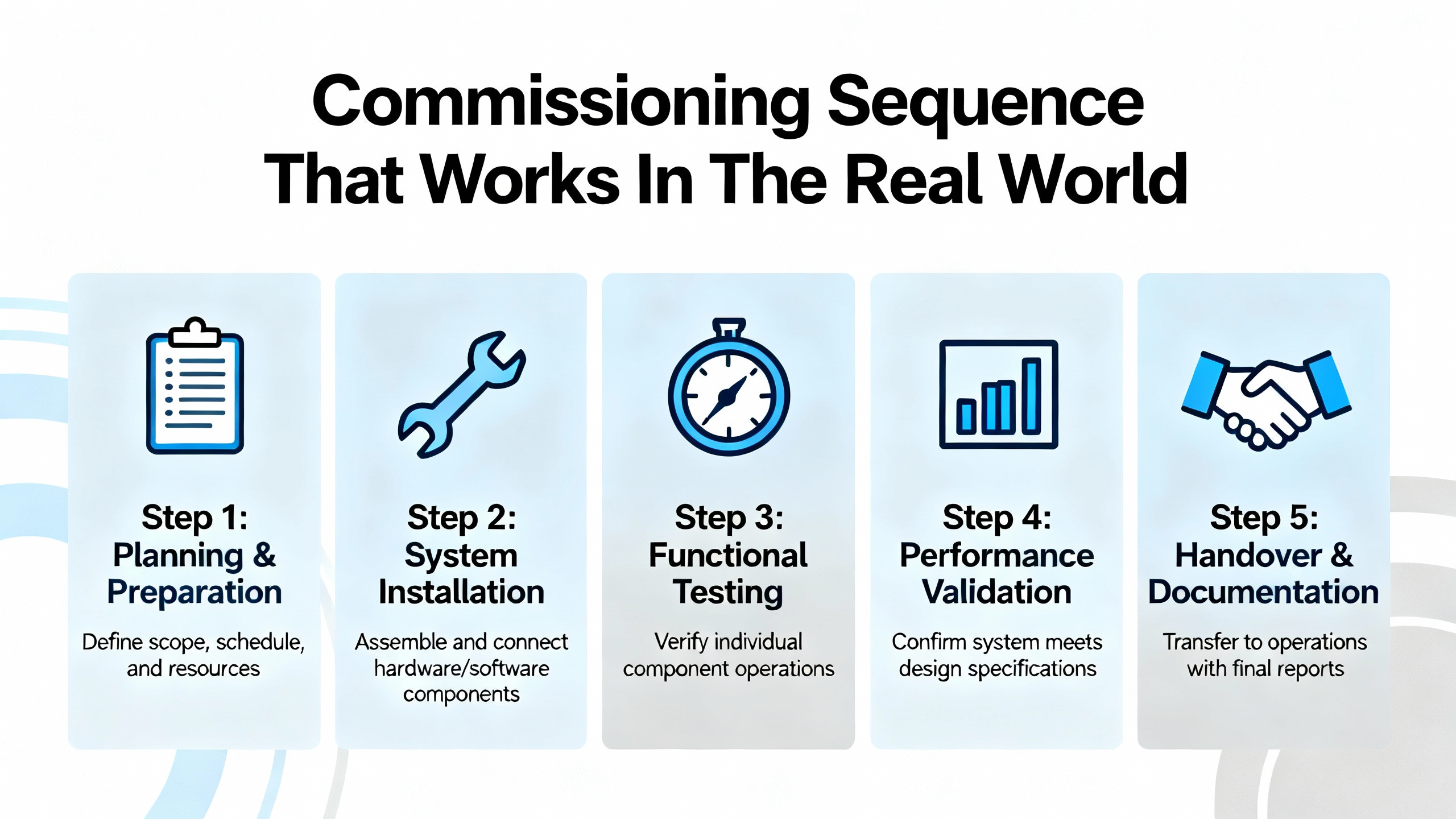
Commissioning Sequence That Works In The Real World
Every ACS880 quick installation or quick installation and safety guide outlines a basic start‑up sequence. The hardware manual adds more detail. Over time I have settled on a pattern that fits within ABB’s documented process but accounts for what actually goes wrong on site.
Begin with a cold review. Before energizing anything, confirm that mechanical installation matches the hardware manual: correct orientation, clearances, and cabinet ventilation. Verify that the nameplate type code matches your design and the correct manual revision. Ensure that ambient conditions in the panel, not just the room, will stay within the specified temperature band.
Next, perform electrical pre‑checks. With the supply locked out, check torque on main and motor terminals against the values in the manual. Verify protective earth connections. Run insulation resistance tests on the motor and cables per your company procedures, being careful to respect any ABB limits on test voltages for connected equipment. Confirm that fuses or breakers match the manual’s recommendations for the specific frame size and supply.
Once you are satisfied with the wiring, power the control electronics and check that the local control panel or keypad boots correctly. Verify that digital input and output status matches your wiring plan using the drive’s diagnostics or the input/output monitoring parameters described in the hardware manual and firmware documentation. It is much easier to debug a stubborn external interlock before you energize the DC bus.
For first start‑up you then energize the mains according to the quick installation guide, keeping the motor uncoupled or unloaded if possible. Using the keypad or ABB’s commissioning tools, enter motor nameplate data exactly as printed. Many ACS880 control programs support a motor identification or autotune routine; the general guidance in ABB manuals is to run that under safe conditions so that Direct Torque Control can build an accurate model of the machine. Skipping that step may leave you with a drive that technically runs but struggles with torque control or protection.
After a successful ID run, perform a low‑speed test in local mode, checking the direction of rotation, current, and any abnormal vibration or noise. Only then should you hand over control to the external system and run under normal load, watching currents, temperature indications, and the drive’s event log for early warning signs.
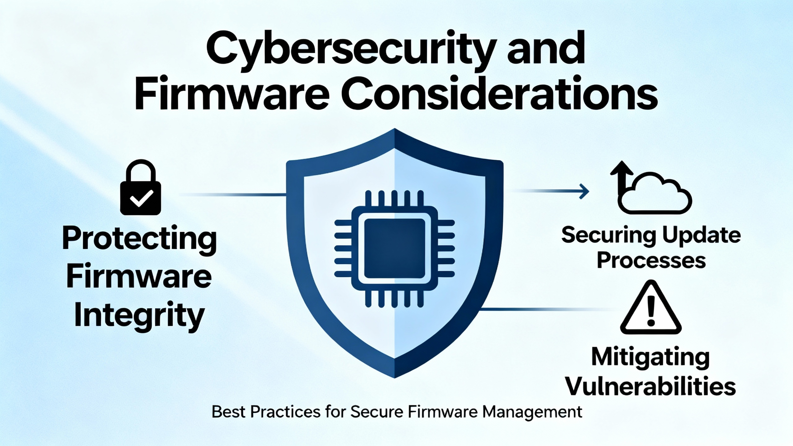
Cybersecurity And Firmware Considerations
In recent years, ABB and public agencies have published advisories about ACS880 variants that include an IEC 61131‑3 control environment based on a CODESYS runtime. A CISA advisory for ACS880 drives that use specific control programs notes vulnerabilities in older CODESYS runtime versions that could be exploited, after authentication, to cause denial‑of‑service or other undesired behavior. ABB’s own security bulletins describe patched firmware versions and recommend disabling online programming communication by default or using parameters to block file downloads when firmware updates are not immediately possible.
For installations where the ACS880 is reachable over plant networks, your installation and commissioning plan should treat the drive as a networked industrial computer as well as a power converter. That means segmenting automation networks behind firewalls, avoiding the temptation to leave programming ports exposed on general office networks, keeping drive firmware and engineering tools patched per ABB guidance, and using VPNs only as part of a defense‑in‑depth strategy rather than a security solution by themselves.
While the hardware manual understandably focuses on electrical and mechanical safety, the same principle applies here: the documented vendor guidance and public security notices are part of the safe‑installation baseline.
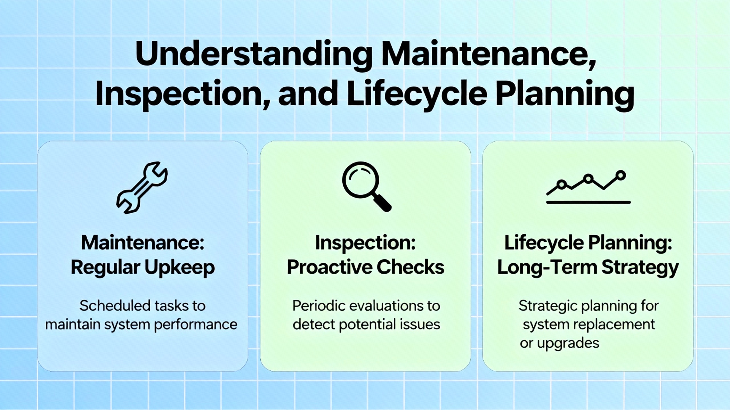
Maintenance, Inspection, And Lifecycle Planning
The ACS880 hardware manuals devote full sections to maintenance and lifecycle. Typical recommendations include periodic inspection of power terminals for tightness and discoloration, cleaning dust or contamination from heatsinks and cooling channels, checking fan operation and listening for unusual noise or vibration, and replacing wear components such as fans at intervals suggested by ABB.
From a practical standpoint, I suggest tying those tasks into your plant’s preventive maintenance program rather than treating them as ad‑hoc checks when a fault occurs. Drives installed in dusty or hot environments need more frequent filter cleaning and inspection. If an ACS880 is mounted in a cabinet that rarely gets opened, you want a planned inspection before the first summer heat wave, not after the drive trips on overtemperature during peak production.
Lifecycle also includes documentation discipline. Hardware manuals advise recording type codes, firmware versions, parameter backups, and any changes to protective settings. When a drive fails halfway through its service life, being able to reload a known‑good parameter set and verify against the hardware manual saves hours of reverse‑engineering anonymous parameter tweaks made during previous shift‑level debugging.
Common Pitfalls I Still See On ACS880 Installations
Even with good manuals, some mistakes are depressingly common.
A frequent one is selecting the drive purely by motor horsepower and voltage rather than motor current and duty cycle, ignoring ABB’s guidance to dimension based on current and overload capability. In applications with high starting torque or cyclic overloads, that often shows up as overcurrent trips during commissioning.
Another is treating EMC recommendations as theoretical. Ignoring shield terminations, mixing control and power wiring in long parallel runs, or leaving built‑in EMC filters incorrectly configured relative to the supply system tends to produce intermittent communication issues, nuisance faults on encoder inputs, or failed EMC compliance tests.
Safe torque off wiring is another recurring issue. I have seen STO circuits jumpered temporarily “just to get it running” and never restored, leaving safety relay contact monitoring non‑functional. The hardware manual and safety option documentation describe exactly how STO circuits must be wired and verified; ignoring that is not just non‑compliant, it is unsafe.
Finally, cabinet thermal design is often underspecified compared to the attention given to bus ratings and fault current. If the hardware manual calls for defined airflow and derating for higher ambient temperatures or altitude, build that into the panel design up front. It is far easier to size fans and ducting before the cabinet is fabricated than to fix overheating on a finished line.
Short FAQ
Do I really need shielded motor and control cables for ACS880 drives? ABB’s hardware manuals for ACS880 variants consistently recommend shielded motor and control cables, with 360‑degree shield terminations and careful routing, as part of EMC‑compliant installations. In my experience, following that guidance prevents a large class of noise‑related issues that are painful to debug later.
Can I rely only on the quick installation guide for commissioning? The quick installation or quick installation and safety guides are designed for essential steps: mechanical mounting, basic wiring, and first start‑up. They assume you will refer to the full hardware and firmware manuals for detailed parameter descriptions, special options, and application‑specific requirements. For anything beyond a very simple, standard application, treating the QIG as your only reference is asking for trouble.
Why does ABB insist on selecting the drive by current instead of motor kilowatts alone? ACS880 hardware manuals emphasize current‑based selection because motors with the same nominal horsepower can have very different nominal currents depending on efficiency, speed, and service factor, and because applications have different overload and duty‑cycle demands. Matching the drive’s current rating and overload capacity to the actual motor current and load profile is the only way to ensure reliable operation and correct protection.
Closing Thoughts
An ACS880 installation that follows the hardware and quick installation manuals looks unremarkable from the outside: clean routing, correct clearances, cool panels, and a drive that simply does its job. The difference is in the early design decisions and the discipline during installation and commissioning. If you treat the manual as part of the drive rather than as a box‑top accessory, your ACS880 projects will be easier to commission, safer to operate, and less likely to wake you up at two in the morning.

References
- https://manuals.plus/m/528f3f34f6415e05cd668bdab7e8a823d180a93c18c4028c82a7cc4df498e0a4
- https://library.e.abb.com/public/426332acfaff4cb98425edeecedd0831/EN_ACS880-11_HW_H.pdf
- https://docs.galco.com/techdoc/abbi/acs880_hm.pdf
- https://www.ittproservices.com/getmedia/8e2171bb-3db8-4f21-a609-708a8b4ba596/EN_ACS880-01_HW_P_A5.pdf
- https://pumpsmart.com/getmedia/5b05f4a2-2171-484f-b61c-29f3afd5915b/PS220-07-Hardware-Manual-75-700HP-(55-560kW).pdf
- https://www.halcyondrives.com/images/documents/drives/ACS880-Drive-Hardware-Manual.pdf
- https://cdn.logic-control.com/docs/abb-drives/acs880/ACS880-01%20Drives%20Frames%20R6%20to%20R9,%20Quick%20Installation%20Guide.pdf
- https://vfds.com/content/manuals/abb/abb-acs880-manual.pdf?srsltid=AfmBOooesIDUjbCzAmajXjuKezx_OdqqHYJTR3VBIEGSM-Z4ojk3Bpoc
- https://www.beta-power.co.uk/wp-content/uploads/2018/02/EN_ACS880-31_hw_B_A5_with-corrections.pdf
- https://www.precision-elec.com/wp-content/uploads/2016/08/ABB-ACS880-VFD-Cooling-Tower-Drive-Option-N5350-User-Manual.pdf?srsltid=AfmBOorn_yopy74ZiGAPlTOAhQNu79iyXXvGM3c4JfRkBim2MRD8-EDM
Keep your system in play!
Top Media Coverage
Categories


Related Products
-
 HIGH LEVEL ANALOG INPUT MODULEManufacturer: Honeywell
 -
CONTROL PROCESSOR MODULEManufacturer: Honeywell
-
DIGITAL OUTPUT CARDManufacturer: Honeywell
-
 variable speed driveManufacturer: Schneider Electric
 -
 FEEDER PROTECTION AND CONTROLManufacturer: ABB
 -
Redundant Power SupplyManufacturer: Honeywell
-
variable speed driveManufacturer: Schneider Electric
-
ANALOG OUTPUT PROCESSOR CARDManufacturer: Honeywell
-
POWER SUPPLYManufacturer: Honeywell
-
DIGITAL INPUT MODULEManufacturer: Honeywell

Related articles Browse All
-
 amikong NewsSchneider Electric HMIGTO5310: A Powerful Touchscreen Panel for Industrial Automation2025-08-11 16:24:25Overview of the Schneider Electric HMIGTO5310 The Schneider Electric HMIGTO5310 is a high-performance Magelis GTO touchscreen panel designed for industrial automation and infrastructure applications. With a 10.4" TFT LCD display and 640 x 480 VGA resolution, this HMI delivers crisp, clear visu...
 -
 BlogImplementing Vision Systems for Industrial Robots: Enhancing Precision and Automation2025-08-12 11:26:54Industrial robots gain powerful new abilities through vision systems. These systems give robots the sense of sight, so they can understand and react to what is around them. So, robots can perform complex tasks with greater accuracy and flexibility. Automation in manufacturing reaches a new level of ...
 -
 BlogOptimizing PM Schedules Data-Driven Approaches to Preventative Maintenance2025-08-21 18:08:33Moving away from fixed maintenance schedules is a significant operational shift. Companies now use data to guide their maintenance efforts. This change leads to greater efficiency and equipment reliability. The goal is to perform the right task at the right time, based on real information, not just ...


- Q&A
- Policies How to order Part status information Shipping Method Return Policy Warranty Policy Payment Terms
- Asset Recovery
- We Buy Your Equipment. Industry Cases Amikong News Technical Resources Why choose us
- ADDRESS
-
 32D UNITS,GUOMAO BUILDING,NO 388 HUBIN SOUTH ROAD,SIMING DISTRICT,XIAMEN
Leave Your Comment