
-
Please try to be as accurate as possible with your search.
-
We can quote you on 1000s of specialist parts, even if they are not listed on our website.
-
We can't find any results for “”.
Allen‑Bradley 1794‑IE8 FLEX I/O Specification: Complete Technical Documentation
The Allen‑Bradley 1794‑IE8 is one of those FLEX I/O modules that shows up everywhere: brownfield PLC‑5 and SLC upgrades, OEM machines that will run for decades, and Logix systems that need economical analog points out on the line. When you understand how this eight‑channel analog input module is built and specified, it becomes a very reliable building block. When you do not, it is easy to end up with one working channel and seven dead ones, or with noisy signals that never quite line up with the transmitter scale.
This article walks through the 1794‑IE8 from a system integrator’s perspective, using the structure and intent of Rockwell Automation’s FLEX I/O installation instructions and analog user manuals. It is meant to sit alongside official publications such as 1794‑IN100 for analog modules, 1794‑UM002 for FLEX I/O analog modules, and 1794‑IN009 for FLEX I/O installation, not to replace them. For final design work, power calculations, and code compliance you should always confirm exact values in those Rockwell Automation documents.
Where the 1794‑IE8 Fits in a FLEX I/O Architecture
The 1794 FLEX I/O family is a modular, distributed I/O platform. Individual I/O modules do not land field wiring directly. Instead, each module plugs onto a terminal base unit that provides the field terminals, backplane connector, and mechanical latching. Those bases then plug into a network or remote‑I/O adapter that connects the FLEX rack to the controller.
Publication 1794‑IN009 from Rockwell Automation describes this architecture clearly: terminal bases keyed to each module type, a common backplane, and adapters that speak Remote I/O, DeviceNet, ControlNet, EtherNet/IP, and other networks depending on catalog number. The 1794‑IE8 sits in that ecosystem as a standard analog input module, usually mounted on DIN rail in a control panel or field junction box and tied back to a PLC‑5, SLC, or Logix controller through the appropriate adapter.
Because FLEX I/O is intended for distributed mounting, the 1794‑IE8 lets you move analog points out near the instruments while the controller hardware stays in a central room. That reduces home‑run cabling, helps with troubleshooting, and keeps analog wires short, which is friendly to noise immunity.

Core Functional Overview of the 1794‑IE8
The 1794‑IE8 is an eight‑channel analog input module for the FLEX I/O platform. According to product notes that catalog used‑market listings, it provides eight independent input channels and is rated for use with analog voltage and current signals. That makes it suitable for typical industrial sensors such as pressure, level, and flow transmitters, as well as panel‑mounted potentiometers and other low‑level devices, so long as their ranges match the module’s supported spans.
The same notes indicate that the module operates from a 24 V DC supply, which aligns with standard control‑panel power systems. As with other FLEX I/O modules, that 24 V DC is delivered through the terminal base and backplane, not wired directly to the module face. The adapter and bases handle backplane and field distribution; the plug‑in module is just the electronics.
FLEX I/O analog documentation such as 1794‑UM002 explains that analog modules in this family convert standard industrial signal ranges into digital values for the controller. Typical ranges in the family include bipolar and unipolar voltages such as plus or minus 10 V and 0 to 10 V, as well as current loops like 0 to 20 mA or 4 to 20 mA. The exact ranges and per‑channel options depend on the catalog and series, so you should always confirm the 1794‑IE8’s range table in the official manual for the specific series you are using.
High‑Level Specification Snapshot
The table below summarizes the key characteristics of the 1794‑IE8 and its FLEX analog relatives, based on Rockwell documentation and product‑information summaries. Any values described as typical or example ranges still need to be confirmed in the official datasheet before you sign off a design.
| Aspect | Description |
|---|---|
| Module type | Eight‑channel analog input module for Allen‑Bradley 1794 FLEX I/O |
| Channels | Eight independent input channels |
| Signals | Designed for analog voltage and current inputs; ranges chosen in configuration per Rockwell manuals |
| Power | Operates from a 24 V DC control‑power supply through the FLEX I/O terminal base and backplane |
| Platform | Plugs onto 1794 FLEX I/O terminal bases and into FLEX I/O network or remote‑I/O adapters |
| Typical use | General industrial automation and process control where distributed analog inputs are needed |
| Documentation | Installation instructions in publication 1794‑IN100 and analog user manual 1794‑UM002 (and related) |
One interesting data point from market listings is the price behavior of this module. A listing cited in the research notes gives an original price near 295 dollars and a current resale price near 92 dollars. That kind of drop is typical of mature modules like FLEX I/O: initial cost is moderate to high, but resale and spares become much more accessible as the platform ages. For lifecycle planning, that means the 1794‑IE8 is still a solid option when you are extending an existing FLEX system, even though Rockwell now promotes newer platforms such as FLEX 5000 I/O and POINT I/O.

Electrical and Performance Characteristics
Rockwell’s analog user manual 1794‑UM002 explains the behavior of FLEX analog modules as a group rather than giving one‑off rules per part number. The 1794‑IE8 follows that pattern. Rather than focus on one absolute number, it is more practical to understand the categories of specification you must check.
The first category is signal ranges. FLEX analog modules support standard industrial ranges such as plus or minus 10 V, 0 to 10 V, and either 0 to 20 mA or 4 to 20 mA. In engineering practice this means the 1794‑IE8 will sit happily between typical field devices and the controller, provided each channel is configured to match the actual transmitter range. The manuals stress that the configuration must match the wiring; a channel configured for voltage but wired with a current loop will not behave predictably.
Another category is resolution and data format. The analog manual notes that modules in this family typically provide 12‑ or 16‑bit resolution, with data presented as integer counts that your controller logic scales into engineering units. The exact resolution and data formatting for a given catalog and series are given in the specification tables, together with the conversion times per channel and overall update rates. When you size scan times and decide how tight your control loops can be, those tables are the ones to consult.

Power and loading are also treated carefully in the Rockwell documentation. The manual for FLEX analog modules calls out backplane current requirements per module, input impedance for voltage and current channels, and the resulting power dissipation. System designers are expected to add up the backplane current for all modules on a FLEX assembly and ensure that the adapter and power supplies can support the total under worst‑case loading and ambient temperature. You should also account for how much heat a fully loaded assembly dumps into a panel, especially in warm process areas.
Finally, the analog manuals discuss accuracy and temperature drift. Rather than rely on generic promises, Rockwell provides per‑catalog accuracy tables across each supported range, often including effects of ambient temperature. In practice, that means you should pull the 1794‑IE8’s accuracy table when doing loop‑tuning calculations or tight material balance work, and treat those figures as part of your measurement‑uncertainty budget.
Mechanical Design, Mounting, and Environment
Mechanically, the 1794‑IE8 behaves like any other FLEX I/O module. The installation instruction bulletins for FLEX, such as 1794‑IN009 and 1794‑IN100, walk through a simple but important sequence.
First, the terminal bases go onto a grounded steel DIN rail. Rockwell’s hazardous‑location instructions for FLEX adapters emphasize that the DIN rail itself is part of the grounding path and should be zinc‑plated steel, not plastic or oxidized metal. Those instructions recommend secure mounting along the rail, with rail fasteners roughly every 8 in or so to ensure solid mechanical and electrical contact. End anchors keep the row of bases from creeping.
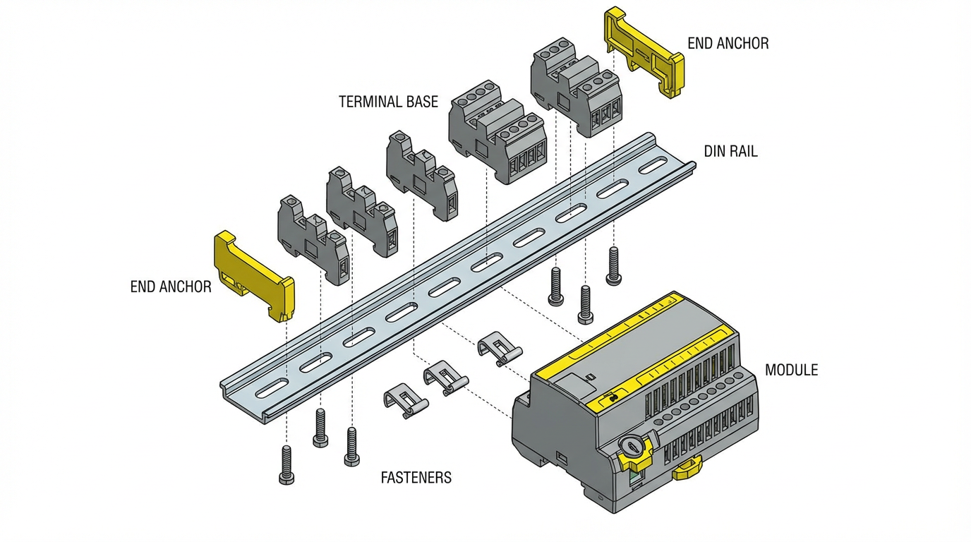
Next, each base is keyed and oriented so that only the correct module type can be inserted. This prevents the classic mistake of dropping an analog module onto a digital base or vice versa, which could miswire power or signals. The 1794‑IE8 then plugs down onto its keyed base and locks with a latch. Correct seating is important; the backplane connector must be fully mated to avoid intermittent analog readings.
Environmental specifications for FLEX I/O assemblies are given in tables in the Rockwell documentation. The EtherNet/IP adapter manual, for example, cites a typical operating temperature range in the neighborhood of 0 to 55 degrees Celsius, which is about 32 to 131 degrees Fahrenheit, for indoor industrial control‑panel use. Actual values for the 1794‑IE8 and for any hazardous‑location certification are listed in the analog installation bulletin and user manual. When you design an enclosure, those temperature, humidity, vibration, and shock ratings are the numbers you should check against your real site conditions.
Wiring the 1794‑IE8 for Clean Analog Signals
The FLEX I/O analog manuals put a lot of emphasis on wiring practices. There is a reason for that. Analog channels are unforgiving if you treat them like basic discrete points.
In those manuals Rockwell recommends copper conductors within specified size ranges and torque values, with shielded twisted‑pair cable for low‑level analog signals, especially in electrically noisy environments. Shields are normally terminated at a single point, often at the control‑cabinet end, to avoid ground loops. The documentation also stresses routing analog cables separately from high‑voltage or high‑current conductors. In a panel layout that translates to physically segregating analog signal duct from motor feeders, contactor wiring, and line‑side power.
The manuals also discuss specific wiring patterns for the different signal modes. Voltage inputs require correct polarity and careful attention to total source impedance. Current inputs must be wired with the loop supply, transmitter, and module channel arranged as recommended, with open‑circuit detection behaving correctly only when loop polarity and power are correct. Channels not in use should be handled according to the manual’s guidance, which might mean leaving them open, shorting them, or tying them to a reference, depending on the module’s design.
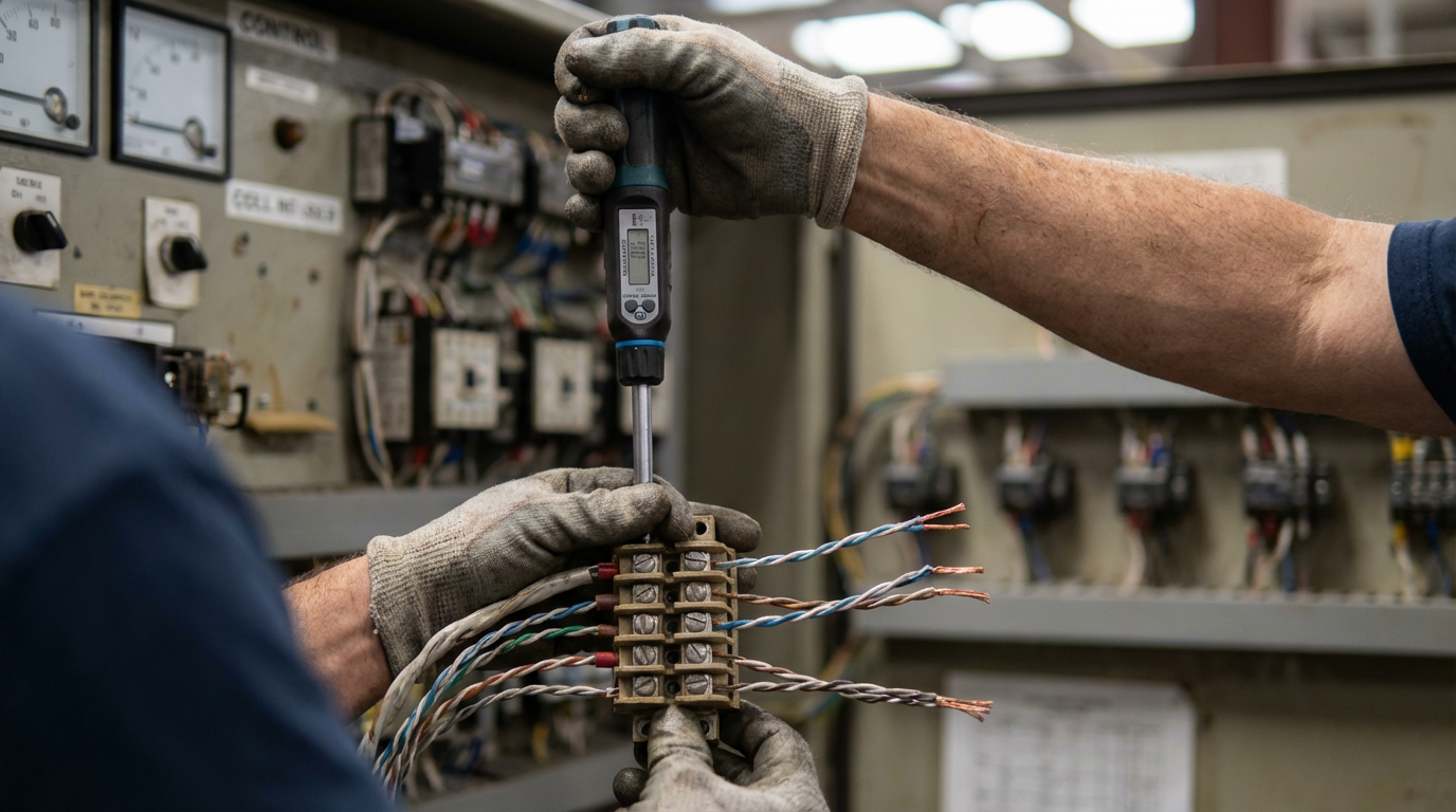
Terminal torque is not just a formality. The installation instructions provide torque values for the screw or clamp terminals. Undertightened terminals can lead to intermittent analog readings; overtightened ones can damage conductors, particularly on smaller gauge cable, leading to long‑term reliability problems. A torque screwdriver set to the values in the manual is not overkill on an analog panel.
Configuration and Scaling in the Controller
From the controller side, the 1794‑IE8 behaves like other FLEX analog modules: you must configure its channels and then scale the raw data into engineering units.
Rockwell’s 1794‑UM002 analog user manual explains that configuration is typically per channel and includes choosing the signal type, choosing the range within that type, enabling any filters or digital averaging, and choosing how the module reports faults such as open wires or overranges. On Logix‑series controllers using Studio 5000, that configuration is often presented as module parameters and per‑channel configuration tags in the I/O tree. On PLC‑5 and SLC systems, configuration is usually done through block transfer instructions.
A forum discussion on MrPLC about “Basic 1794‑IE8 Setup” highlights one of the most common field problems with older platforms. In that thread, a user had a test setup with an SLC 5/03 in a seven‑slot rack, a 1747‑SN scanner, a 1794‑ASB adapter, two OB16 output modules, one IB16 input module, and one 1794‑IE8 series B analog module. All discrete I/O worked. The analog module did not, except for channel zero. Only after changing the Block Transfer Write data file so that two configuration words with the value minus 256 were written did all eight channels appear to function.
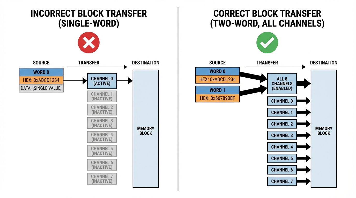
The manuals for the 1794‑IE8 describe a configuration structure that, in that user’s reading, fits into a single word, and the example PLC‑5 ladder agrees. The mismatch between the expected one‑word configuration and the observed two‑word behavior led to confusion and lack of confidence in the configuration. The thread underscores two practical points. First, on PLC‑5 and SLC systems you must pay close attention to the exact word count and layout of the configuration block described in the analog installation instructions, and make sure your BTR and BTW instructions are sized to match, including any module‑series‑specific options. Second, “magic” values such as minus 256 that appear to make everything work should send you back to the manual to understand what bits you have actually set, rather than relying on trial and error.
On Logix controllers you avoid block transfers, but the same principle applies. The configuration dialog in Studio 5000 is just an interface to the same parameters that are described in the analog user manual. You still need to map each channel’s raw integer value to engineering units using the documented scaling information for the chosen range, and you still need to decide how to react in logic to overrange, underrange, and open‑wire conditions that the module flags.
Diagnostics, Faults, and Maintenance
FLEX installation instructions such as 1794‑IN009 describe a common diagnostic pattern across modules. There are module‑level LEDs for power and status, and on many analog modules there are per‑channel status indicators as well. These LEDs indicate whether the module has power, whether communication with the adapter and controller is healthy, whether I/O is being scanned, and in some cases whether a channel is in alarm.
The analog manuals expand on this by describing the diagnostic bits that appear in the controller data structure for each channel. Typical flags include overrange, underrange, and open‑circuit detection for current loops. Just as important as knowing these bits exist is deciding how you will use them. In a well‑behaved system, you would normally latch an alarm or interlock when an analog safety‑relevant input goes open‑circuit or overrange, rather than simply treating it as a transient glitch.
Routine inspection is also covered in Rockwell’s installation bulletins. The instructions recommend periodic checks for loose wiring, damaged components, environmental contamination on the module faces and terminal blocks, and the condition of DIN‑rail grounding and mounting hardware. Replacement parts and accessories are expected to be Rockwell‑specified ones so that mechanical fit, electrical ratings, and hazardous‑location approvals are maintained. Those recommendations sound basic, but they are exactly the kind of discipline that keeps FLEX I/O installations running for years without mysterious analog drift.

Safety, Hazardous Locations, and ESD
Several Rockwell publications for FLEX I/O, adapters, and analog modules devote their front pages to safety conventions. They define notation such as “WARNING” and “ATTENTION” and tie those to risks like electric shock, arc flash, fire, or equipment damage. The analog and installation manuals require that only suitably trained personnel perform installation, adjustment, commissioning, and maintenance, and that all work comply with local codes such as the National Electrical Code in the United States.
Hazardous‑location bulletins for FLEX adapters, such as publication 1794‑IN082C‑EN‑P, add another layer for Class I, Division 2 and similar environments. Those instructions warn that inserting or removing modules on a powered backplane, or connecting and disconnecting communications or field wiring under power, can cause electrical arcing. In a hazardous location, that arc is a potential ignition source. The guidance is straightforward: either remove power before working, or verify that the area is nonhazardous. The same principle applies when you plug or unplug an analog module like the 1794‑IE8 from its base.
Electrostatic discharge is also called out explicitly. The FLEX documentation reminds users that modules are ESD‑sensitive devices. Handling recommendations include discharging static by touching a grounded object, wearing a grounding wrist strap, avoiding contact with connector pins and circuit boards, using static‑safe workstations, and storing modules in static‑safe packaging. Skipping those precautions may not bite you immediately, but latent ESD damage can shorten the life of analog electronics in unpleasant ways.
Choosing When to Use the 1794‑IE8
From a project‑planning standpoint, the 1794‑IE8 is most attractive in a few scenarios.
It is a natural choice when you already have a FLEX I/O infrastructure in place, for example on legacy PLC‑5 or SLC systems with 1794‑ASB adapters, or on Logix systems using FLEX EtherNet/IP or ControlNet adapters. In those situations, dropping in a 1794‑IE8 avoids the cost and complexity of introducing a second I/O platform solely for analog.
It is also a good fit where you need a moderate number of analog inputs per location. With eight channels in a single module, you can pick up a cluster of transmitters in a skid or local junction box without burning excessive panel space. Rockwell’s analog manuals describe variations of the analog modules with different combinations of voltage and current channels and different ranges; the 1794‑IE8 is the pure analog input member of that family.
On the other hand, when you are designing a new system with no existing FLEX footprint, you should weigh FLEX against newer modular I/O like POINT I/O or FLEX 5000 I/O. Newer platforms may offer higher density, enhanced diagnostics, or tighter integration with current controllers. The research notes mentioning a significant price gap between the original and resale pricing of the 1794‑IE8 reinforce that it is a mature product. That is not a problem in itself, but it is a reminder to check lifecycle status and see whether Rockwell has issued any migration advisories.
Practical Implementation Checklist
Even though the detailed numbers live in the Rockwell manuals, the pattern for a reliable 1794‑IE8 installation is consistent.
You make sure the mechanical foundation is sound: grounded steel DIN rail, proper base keying, solid latching of modules, and enclosure ratings that match your environment. You wire analog circuits with shielded twisted‑pair where appropriate, segregate them from power circuits, observe the specified conductor size and torque limits, and follow Rockwell’s recommended wiring diagrams for each signal type.
You configure each channel intentionally in your controller software, with ranges and data formats that match the wiring. On PLC‑5 and SLC systems you verify block transfer lengths and data structures against the analog installation bulletin so that all channels are truly configured, not just channel zero. On Logix systems you verify that the module definition and revision in Studio 5000 match the physical module and that scaling logic is correct.
You incorporate diagnostics: map channel overrange, underrange, and open‑wire flags into your alarming strategy, and build maintenance procedures that include checking FLEX module LEDs and wiring as part of routine inspections.
And you take the safety conventions seriously, particularly in hazardous locations and on energized systems, where the consequences of violating the warnings in Rockwell’s installation bulletins can be more severe than a simple module failure.
Brief FAQ
Where do I find the exact numerical specifications for the 1794‑IE8? Rockwell Automation’s official sources are the relevant installation instructions and the FLEX analog user manual. Publications such as 1794‑IN100 for FLEX analog modules and 1794‑UM002 for analog module behavior provide the detailed tables for ranges, resolution, accuracy, conversion times, power dissipation, and environmental ratings. Always use the revision that matches your module’s catalog and series.
Does the 1794‑IE8 support both voltage and current on the same module? FLEX analog documentation explains that modules in this family are designed to handle standard industrial voltage and current ranges, and that channels are configured in the controller for particular ranges. The specific mix of ranges available per channel on the 1794‑IE8, and whether all channels are individually selectable, is defined in its Rockwell datasheet and user manual. You should review those tables before deciding how to assign signals.
What should I do if only one channel appears to work on a PLC‑5 or SLC system? Community discussions, including examples on forums such as MrPLC, show that mis‑sized or mis‑structured Block Transfer Read and Block Transfer Write files are a frequent cause of “channel zero only” symptoms. The correct remedy is to compare your block transfer configuration length and word layout with the module’s installation instructions and adjust the logic to match, rather than rely on trial‑and‑error values.
Closing
The 1794‑IE8 is not flashy, but in plants that still rely on FLEX I/O it is often the workhorse analog input module that quietly carries critical process measurements back to the controller. Treat the Rockwell documentation as your ground truth, follow the wiring and configuration discipline those manuals describe, and this module will behave predictably for years. If you design and commission it with that level of respect, it will repay you with stable signals and far fewer late‑night troubleshooting calls.
References
- https://projects.mcah.columbia.edu/amiens-arthum/sites/default/files/VR/North/?pano=data:text%2Fxml,%3Ckrpano%20onstart=%22loadpano(%27%2F%5C%2Fp6.pics%2Fp%2F10824185884%27)%3B%22%3E%3C/krpano%3E
- https://www.plctalk.net/forums/threads/1794-ie8-scaling-in-plc-5.25017/
- https://assetcloud.roccommerce.net/files/_smcelectric/9/7/6/allen_bradley_5094_ib16_user_manual.pdf
- https://www.artisantg.com/info/AB_1794_Series_Manual.pdf?srsltid=AfmBOooPAAoK1LHXhvHSJfnFyiHioQ8CRB8sdI8xQ7bNd0EBjtLATObS
- https://manuals.plus/asin/B0CH5BDZGX
- https://docs.rs-online.com/aee9/0900766b8033e0b7.pdf
- https://www.ideadigitalcontent.com/files/11994/1794-in096_-en-p.pdf
- https://www.scribd.com/document/547080662/1794-aent
- https://mrplc.com/forums/topic/20072-basic-1794-ie8-setup/
- https://sonicautomation.co.th/wp-content/uploads/2019/12/RA_FLEX-5000-IO-digital-module-user-manual.pdf
Keep your system in play!
Top Media Coverage
Categories


Related articles Browse All
-
 amikong NewsSchneider Electric HMIGTO5310: A Powerful Touchscreen Panel for Industrial Automation2025-08-11 16:24:25Overview of the Schneider Electric HMIGTO5310 The Schneider Electric HMIGTO5310 is a high-performance Magelis GTO touchscreen panel designed for industrial automation and infrastructure applications. With a 10.4" TFT LCD display and 640 x 480 VGA resolution, this HMI delivers crisp, clear visu...
 -
 BlogImplementing Vision Systems for Industrial Robots: Enhancing Precision and Automation2025-08-12 11:26:54Industrial robots gain powerful new abilities through vision systems. These systems give robots the sense of sight, so they can understand and react to what is around them. So, robots can perform complex tasks with greater accuracy and flexibility. Automation in manufacturing reaches a new level of ...
 -
 BlogOptimizing PM Schedules Data-Driven Approaches to Preventative Maintenance2025-08-21 18:08:33Moving away from fixed maintenance schedules is a significant operational shift. Companies now use data to guide their maintenance efforts. This change leads to greater efficiency and equipment reliability. The goal is to perform the right task at the right time, based on real information, not just ...


- Q&A
- Policies How to order Part status information Shipping Method Return Policy Warranty Policy Payment Terms
- Asset Recovery
- We Buy Your Equipment. Industry Cases Amikong News Technical Resources Why choose us
- ADDRESS
-
 32D UNITS,GUOMAO BUILDING,NO 388 HUBIN SOUTH ROAD,SIMING DISTRICT,XIAMEN
Leave Your Comment