
-
Please try to be as accurate as possible with your search.
-
We can quote you on 1000s of specialist parts, even if they are not listed on our website.
-
We can't find any results for “”.
Shock- and Vibration-Resistant Controllers: Making Military Standard Compliance Real
Why Shock and Vibration Matter So Much for Controllers
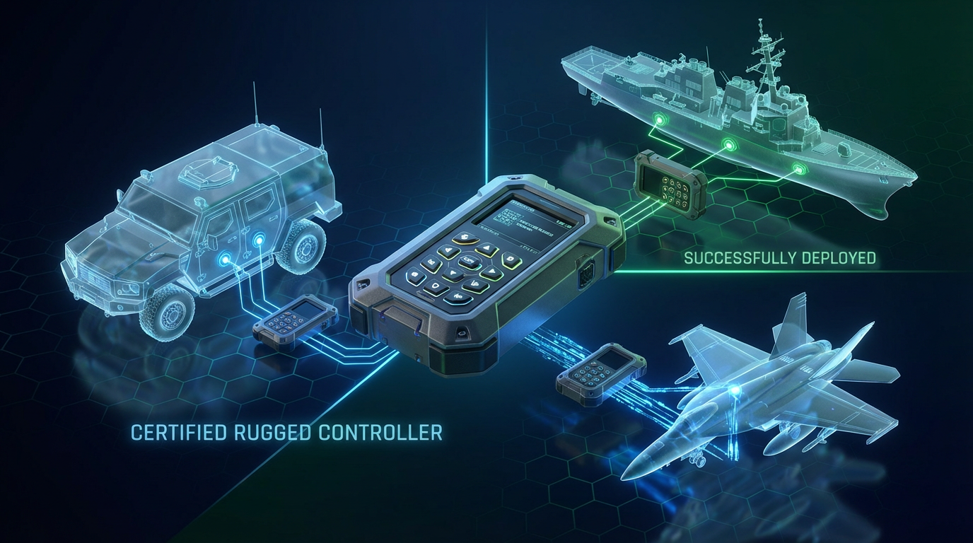
Any controller that goes beyond a quiet lab bench and into a ground vehicle, a ship, an aircraft, or a remote unmanned system will live in a world of shock and vibration. Engines, tracks, propellers, rough seas, weapon fire, and even how the unit is transported will punish both the electronics and the mechanics every day. LCR Embedded Systems notes that military electronics in ground vehicles, aircraft, and ships are exposed to continuous vibration and extreme shock from terrain, turbulence, rough seas, rotating machinery, and nearby munitions. If you design or integrate controllers for these platforms, you are designing for that reality whether you acknowledge it or not.
Shock and vibration are related but not the same problem. As several defense and vibration isolation vendors explain, vibration is a continuous or repetitive oscillatory motion at some frequency and magnitude. Shock is a sudden change in velocity, often a short, high-acceleration event such as an explosive event, collision, or rough impact in transport. From a controller’s standpoint, vibration tends to fatigue solder joints, connectors, and mechanical structures over time, while shock can break things outright in a single event.
Trenton Systems catalogs the kinds of failures you see when vibration is not controlled: chafed wiring, loose fasteners and components, intermittent contacts, electrical shorts, deformed seals, cracked or broken structures, particle debris in circuitry, mechanical or optical misalignment, and even fretting corrosion in bearings. Anyone who has debugged an intermittent controller reset on a vehicle platform under vibration has seen some version of this list in real life. The job is not simply to “make it pass the test.” It is to design and qualify the controller so that it keeps performing in that environment for years.
The Standards Landscape: What “Military-Grade” Really Implies
When people talk about a “shock- and vibration-resistant controller” in the defense world, they are usually pointing, directly or indirectly, to formal military or aerospace standards. Different standards focus on different environments and frequency ranges, and it is common to apply more than one.
| Standard or guideline | Primary focus (from vendor briefs) | Typical relevance to controllers |
|---|---|---|
| MIL-STD-810 Method 514.8 | Vibration tests covering transportation, storage, and operation across vehicles, aircraft, ships, and logistics transport; aims to keep equipment functional and structurally sound | Baseline vibration qualification for servers, vehicle controllers, handheld units, and mission computers |
| MIL-STD-167-1A | Low-frequency mechanical vibration of shipboard equipment, including externally induced (Type I) and internally excited (Type II) vibration | Naval control systems, power controllers, and racks bolted to ship structures |
| MIL-STD-901 or MIL-S-901 | High-intensity shipboard shock, often used alongside MIL-STD-167 | Shipboard controllers that must survive severe shock events |
| MIL-STD-461 | Electromagnetic compatibility and emissions for military equipment | Controllers with rugged HMIs, radios, EW interfaces, and sensitive electronics |
| MIL-STD-1472 | Human factors and ergonomics for military systems | Controller HMIs, keyboards, and control panels used by operators |
| DO-160 and aerospace standards | Environmental tests for aerospace platforms, often including vibration and shock | Airborne mission computers and controllers where aviation requirements apply |
Defense-focused vendors such as Trenton Systems describe how MIL-STD-810 vibration testing, specifically Method 514.8, is used to validate that rugged servers and controllers remain both functional and structurally sound under realistic vibration. MIL-STD-810H provides environment categories and test procedures such as tied-down general vibration, loose cargo transport, large assemblies tested on vehicles, and aircraft captive or free-flight stores. Programs that expect severe environments are advised to explicitly call out MIL-STD-810H Method 514.8 compliance in design, bid, and procurement documents, and to obtain formal test reports from qualified laboratories when in-house capability is limited.
On the naval side, IDC explains that MIL-STD-167-1A is used to vibration-qualify mechanical and electrical equipment on surface ships. The goal is to ensure structural integrity and functional reliability in the presence of low-frequency vibration generated by waves, propellers, engines, and hull motion. The standard distinguishes between Type I environmental vibration that comes from the ship structure and sea state, and Type II internally excited vibration generated by rotating or reciprocating elements inside the equipment itself. Type I testing typically sweeps from roughly 4 to 33 Hz in three axes. When significant resonances are found, the standard calls for dwells at those frequencies long enough to prove that fasteners, solder joints, and assemblies can withstand sustained vibration without damage or performance loss.
MIL-STD-167 is frequently paired with shipboard shock standards such as MIL-S-901 or MIL-STD-901 for high-intensity shock, and that combination is often layered on top of MIL-STD-810 environmental tests. LCR Embedded Systems highlights MIL-STD-810 and MIL-STD-901 as primary standards for shock and vibration testing of defense electronics. Rugged HMI suppliers also call out MIL-STD-810 for shock, vibration, and temperature, along with MIL-STD-461 for EMC and MIL-STD-1472 for ergonomics. For handheld controllers used in defense and underwater applications, Ocean Science & Technology notes that these units are often built to MIL-STD specifications and to ingress protection ratings such as IP67, and are designed to continue operating in shock- and EMI-prone environments.
The takeaway is straightforward. If you are specifying a shock- and vibration-resistant controller, you are really specifying which combination of standards and methods it must meet, on which platforms, and in which life-cycle phases. Without that clarity, “rugged” is just a marketing adjective.
How MIL-STD-810 Method 514.8 Treats Vibration
MIL-STD-810 Method 514.8 is central to controller survivability because it explicitly addresses both the operational and transportation environments. A summary from CVG Strategy emphasizes that its primary goals are to reproduce expected service vibration in the lab, assess structural integrity, identify resonant frequencies, and verify that mission-essential functions continue under vibration.
The method distinguishes between operational vibration, where the item is powered and performing its function in its platform, and non-operational vibration during transport, handling, and storage. These conditions may use different severities, durations, and pass or fail criteria. In other words, the controller may be allowed to be powered off in some transportation tests, but it cannot fall apart internally.
From a technical perspective, Method 514.8 uses vibration environments defined by power spectral density profiles and overall root-mean-square acceleration, with swept-sine profiles in some cases. The standard provides example spectra and guidance on how to derive tailored profiles from field data, so a controller mounted on a tracked vehicle sees a different profile than one in a shipboard rack.
Several vendors stress one point repeatedly: test tailoring. The standard itself encourages using measured or well-documented field vibration data, considering installation location and mounting method, and aligning test levels and durations with the actual mission and life-cycle exposure. Running generic worst-case profiles without tailoring can either under-test the control hardware or punish it unrealistically.
Method 514.8 is also prescriptive about how you set up the test. Fixtures and mounting hardware must realistically reproduce the stiffness, mass distribution, and boundary conditions of the intended installation. Instrumentation must use properly calibrated accelerometers and adequate control channels for closed-loop random vibration. Both input and response points are monitored to prevent either over-testing or under-testing the controller.
Analytical work before testing is strongly encouraged. Modal analysis or finite element modeling can identify sensitive frequencies and inform axis selection and notching strategies. The standard allows you to notch or limit test levels at specific resonances if analysis shows that full levels would exceed design margins or create unrealistic damage, but you must justify and document any reductions.
Functional checks before and after vibration exposure, and when feasible during exposure, are integral to the method. Post-test inspections focus on cracks, loose fasteners, connector issues, and misalignment. Documentation requirements are significant: you must record the test configuration, profiles, instrumentation, tailoring rationale, anomalies, and deviations so that the qualification decision is defensible.
From the integrator’s standpoint, this means you cannot treat vibration as a simple “pass or fail” stamp. You have to think about how the controller is mounted, how it is cabled, and how it will actually be used. If you do that work up front, MIL-STD-810 becomes a validation step rather than a roulette wheel.

Shipboard Controllers and MIL-STD-167 Vibration
Controllers installed on naval platforms, particularly those bolted to decks, bulkheads, or foundations near heavy machinery, live in a very different vibration world than those in a server rack ashore. IDC’s discussion of MIL-STD-167-1A lays out what that environment looks like.
Type I environmental testing uses swept-sine excitation in about the 4 to 33 Hz range on three orthogonal axes. The purpose is to uncover structural resonances driven by waves, propellers, engines, and overall hull motion. Once resonances are identified, the test dwells at those frequencies for defined durations to demonstrate that structures, fasteners, and solder joints can survive long-term exposure.
Type II testing applies when the equipment itself contains rotating machinery or other internally excited sources. This test uses discrete-frequency excitation at critical running speeds and harmonics to replicate the vibration the equipment generates. For controller assemblies that include internal fans or other moving components, or that are mounted on machinery frames, these tests absolutely matter.
As with MIL-STD-810, MIL-STD-167 requires that tests be run on production-representative hardware mounted on fixtures that approximate the real shipboard foundation, including mass and center of gravity, not just a bare board on a lab shaker. The standard focuses on low-frequency vibration fatigue and structural integrity and is commonly used alongside high-intensity shock standards and broader environmental qualification.
IDC stresses that design teams should determine early whether their system will require Type I, Type II, or both, and design structures, enclosures, and internal assemblies with enough stiffness and margin at likely resonance frequencies. Practical mitigations include using vibration isolators or tuned mounts, increasing stiffness where necessary, and carefully balancing and aligning rotating assemblies to reduce internally generated vibration.
For a controller integrator, that means treating the mounting interface and the local structure as part of the controller design, not someone else’s problem. If you bolt a beautifully designed controller into a flexible ship structure without the right isolators, you can still lose.

Fundamentals of Vibration Isolation Around the Controller
Most controllers cannot survive military vibration and shock solely through thicker PCBs and extra screws. They rely on the mechanical system around them: isolators, mounts, and chassis. Several isolation specialists describe the basic elements the same way. A vibration control system consists of the equipment mass, the support structure, and a resilient isolator placed between them. Isolation can be needed in either direction. When the controller is the source, isolators reduce forces into the structure. When the structure is the source, isolators reduce motion transmitted into the controller. In both cases, the isolator stores incoming energy and releases it over time to reduce the transmitted disturbance.

The physics behind this is well established. Every mass–spring–damper system has a natural frequency, the rate at which it will oscillate if displaced and released. When a forcing frequency coincides with this natural frequency, resonance occurs and the response is amplified instead of reduced. The same references note that isolator effectiveness is typically described by transmissibility, the ratio of transmitted to input motion or force. Transmissibility peaks at resonance and drops off at higher frequency ratios. Designers of shock- and vibration-resistant controllers therefore aim to select isolators so that the combined controller–mount system has natural frequencies that are not excited by the dominant platform vibration or by any critical frequencies of the controller itself.
Damping is equally important. Real mounts dissipate energy through mechanisms such as dry friction, hysteresis in elastomer materials, or viscous effects. A certain amount of damping is crucial to control motion at resonance and prevent prolonged ringing after a shock event. However, too much damping can compromise high-frequency isolation. These tradeoffs explain why different isolator technologies exist.
Choosing the Right Isolation Technology for Controllers
Industrial and defense vibration vendors provide a broad portfolio of isolators that can be applied around controllers, each with distinct strengths.
Elastomeric mounts and bushings, often made from natural rubber, neoprene, silicone, or EPDM bonded to metal, are widely used. Hutchinson and GMTR Rubber describe them as cost-effective solutions that provide both vibration isolation and shock absorption, suitable for large motors, generators, and general machinery. Rubber mounts inherently provide damping and can protect in multiple directions. They are also resistant to grease and oil, which makes them popular around engines and generators in automotive and marine applications. For controllers mounted in these environments, elastomeric mounts can be an effective first line of defense if the loads and deflections are well understood.
Wire rope isolators are a different class entirely. Isotech and LCR Embedded Systems highlight metal wire rope isolators as the dominant solution across many Department of Defense applications, from small ATR chassis to full rack systems. GMTR Rubber notes that stainless-steel wire rope mounts are corrosion-resistant, maintenance-free, and isolate shock and vibration in all directions. They can be tuned for low natural frequencies, provide highly damped response, fit into tight spaces, and handle temperature extremes and corrosive environments. They are especially important in harsh military applications and have been certified to standards such as MIL-STD-167 for vibration, MIL-STD-810 for environmental exposure, and MIL-S-901 for shock. For controllers that must ride through gunfire, launch shocks, or severe shipboard events, wire rope isolation is often the only realistic option.

Spring-based isolators are another tool. Isotech describes heavy-duty spring mounts used on engine-generator sets, fans, and HVAC equipment, where they control vibration from imbalance and limit structure-borne vibration and high-frequency noise. With proper design and sometimes with added elastomer elements for damping, they can be used to isolate controller cabinets or entire skid assemblies from building or ship structures.
Additional technologies fill niche roles. Vibration isolation pad mounts made from rubber, cork, or foams provide economical isolation and good high-frequency sound attenuation but are best for medium to high speed equipment in non-critical installations. Ceiling hangers isolate suspended piping and equipment, sometimes combining elastomer and springs to cover both high and low frequencies. Roof mounts integrate spring isolation into structural frames to keep rooftop equipment from injecting noise and vibration into buildings. Greene Rubber describes resilient mounts developed specifically for U.S. Navy applications, including G Series pipe hangers, Mare Island mounts, and EES series machinery mounts that meet naval specifications and provide low-frequency isolation in harsh marine service.
Defense-focused articles agree on several practical points. Requirements for shock and vibration should be analyzed separately because they are governed by different principles, and the more severe environment usually drives the design. Sometimes you must accept a compromise isolator that reasonably addresses both. Correctly specified anti-vibration mounts protect machinery, structures, and workers, extend equipment life, and lower lifecycle costs. When standard mounts cannot meet requirements, vendors emphasize the value of engaging specialist engineers who can help select or design suitable mounts early in the project.
For controllers, that means you rarely select isolation in isolation. You consider the platform vibration spectrum, the controller’s mass and mounting pattern, allowable deflection, and the mission’s shock envelope, then choose the mount type accordingly. Wire rope and springs tend to be favored for low-frequency and harsh conditions, while elastomer mounts and pads are more often used for structure-borne and higher-frequency cases or non-critical equipment.
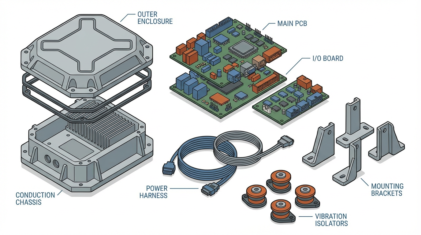
Controller Packaging: Chassis, HMIs, and Cabling
The physical packaging of a controller contributes just as much to survivability as the bare PCB or the isolators under the enclosure.
LCR Embedded Systems describes how rugged conduction-cooled ATR chassis for VPX and SOSA-aligned electronics address shock and vibration at the packaging level, both inside and outside the chassis. In the VITA 48.2 REDI approach, boards sit in aluminum housings that lock into aluminum chassis rails. While this design is primarily about thermal management, it also eliminates board vibration and reduces connector and component fatigue. Recommendations at the chassis level include robust mechanical locking features, rigid structures, and careful routing and stabilization of internal cables to prevent movement, connection stress, and vibration-induced failures. They also emphasize that the most effective mitigation is to limit force transfer into the chassis using external isolation systems rather than relying solely on internal ruggedization.
Rugged HMI suppliers bring a complementary view from the operator interface side. Defense Advancement notes that rugged HMIs use sealed enclosures, gaskets, reinforced frames, shock-mount structures, and EMI shielding to withstand vibration, impact, humidity, and temperature extremes. Rugged keyboards, joysticks, pointing devices, and displays are designed for use in combat vehicles, naval control rooms, and command centers where commercial off-the-shelf peripherals would quickly fail. Engineering requirements include reinforced housings, shock mounts, protective anti-corrosion and abrasion coatings, sealed wiring harnesses, and vibration-resistant connectors. These systems are commonly integrated into panels that tie directly to controllers, power distribution, sensors, and mission software.
In mobile machine control, HED describes rugged controllers designed for demanding heavy vehicle environments. They communicate over J1939 CAN and CANopen networks and are supported by software tools and board support packages. While the brief does not list specific shock and vibration standards, in practice these types of controllers often sit in the same conduction-cooled chassis or sealed enclosures described above, mounted through isolators and subject to the same military tests.
Underwater and surface unmanned systems provide a different form factor. Ocean Science & Technology describes handheld controllers for ROVs, UUVs, and USVs that combine joysticks, touchscreens, inertial sensors, and multiple connectivity options. For defense missions such as mine countermeasures, harbor patrol, and hull inspection, these handheld units are often built to MIL-STD requirements and to ingress protection ratings such as IP67, and are designed to function in electromagnetic and shock-prone environments. They add practical design features such as rugged housings, backlit controls for low-light conditions, secure cable management, long battery life, and fast boot and reconnect times for mission continuity.
Across these packaging examples, the pattern is the same. The enclosure, mounts, connectors, cables, and HMI hardware are all part of the shock- and vibration-resistant controller. When any of those are treated as an afterthought, the system fails at the weakest link.
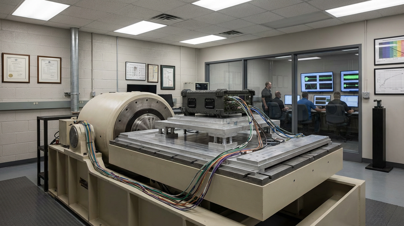
How Lab Vibration Controllers Enable Compliance
Behind every MIL-STD qualification report is a vibration control system driving the shaker. Spectral Dynamics describes its PANTHER system as a single-axis vibration controller designed for mission-critical defense and aerospace testing where failure is not an option. With more than eighty years of vibration control experience and a history as an early inventor of closed-loop digital vibration testing, the company focuses heavily on precise control and honest specifications. PANTHER offers dynamic range greater than 110 dB, amplitude accuracy and linearity on the order of plus or minus 0.20 percent, true 24-bit analog-to-digital conversion, and sampling rates up to 262,144 samples per second.
For MIL-STD-810 vibration and other military standards such as MIL-STD-167, MIL-STD-202, and MIL-STD-750, PANTHER provides preconfigured test profiles, automatic tolerance monitoring, and mission simulation features that automate complex sequences of sine, random, shock, and temperature cycling. According to Spectral Dynamics, this combination of capabilities has reduced qualification testing time and documentation effort while eliminating failures due to tolerance violations through real-time monitoring and automatic abort functions.
When controllers must survive extreme weapon system environments, shock capabilities become critical. Spectral Dynamics reports that PANTHER supports both classic shock pulses used in MIL-STD-810 shock testing and synthesized shock response spectra for more complex waveforms. Patented adaptive equalization compensates for shaker and fixture nonlinearities in real time, enabling accurate reproduction of high-g shock pulses. The system implements multiple safety checks per second and redundant hardware safety relays to protect expensive test articles. Documented results include improved accuracy on high-g pulses, reduced test article damage, and elimination of time-consuming manual equalization iterations.
For sensitive electronics such as radar and electronic warfare systems, PANTHER’s high dynamic range, low noise, and multiple independent data streams with up to thirty-two phase-synchronized channels allow test engineers to correlate vibration exposure with subtle performance degradations. Examples cited include detection of intermittent failures that previous testing missed and reductions in false failure indications. In aircraft structural testing, capabilities such as adaptive sine tracking, tight frequency accuracy, automatic resonance detection and dwell, and accurate transfer function measurement support advanced modal analysis and validation of flight profile simulations.
From a systems integrator’s perspective, the exact brand of vibration controller is less important than the principle. Shock- and vibration-resistant controllers are not just designed; they are also credibly tested. That requires tightly controlled test equipment, appropriate fixtures, and automatic documentation that aligns with the standards.
When you review a vendor’s compliance claims, the quality of their test methodology matters as much as the numbers on the datasheet.
Practical Design and Procurement Advice from a Systems Integrator’s View
Over the years, the projects that have gone smoothly on shock and vibration all shared a few habits, and those habits line up closely with the guidance from the standards and from the vendors cited here.
First, define the environment and standards early. Decide whether your controller is going into ground vehicles, aircraft, ships, or unmanned systems, and map each platform to specific standards and procedures. For a naval controller, that probably means MIL-STD-167 Type I and possibly Type II, plus a shipboard shock standard. For a vehicle or airborne controller, it often means MIL-STD-810 Method 514.8 and possibly additional defense or aerospace standards. For handheld controllers for underwater operations, you may add ingress protection ratings and electromagnetic compatibility requirements on top of the shock and vibration expectations.
Second, treat mechanical design and isolation as part of the controller, not as a field fix. Use the vibration isolation fundamentals described by companies such as Hutchinson, GMTR Rubber, Isotech, Greene Rubber, and IDC. Understand the mass and mounting of the controller, estimate static deflection where appropriate, and choose isolator technologies that fit the vibration spectrum and environment. Wire rope isolators are usually the workhorse when you need low-frequency isolation, all-attitude capability, and survival in harsh military conditions. Elastomeric mounts provide damping and can be excellent around engines and generators. Spring and combined mounts can handle heavy assemblies and mixed frequency ranges. When in doubt, involve the isolation vendor’s engineers rather than guessing.
Third, design your packaging for both internal and external robustness. Follow chassis and HMI practices such as conduction-cooled housings, rigid structures, positive mechanical locking of boards, stabilized cabling, and sealed connectors. Make sure all services into the controller, including exhausts, piping, and harnesses, allow the unit to move on its mounts without imposing rigid constraints that bypass the isolators. Several vibration mount guides specifically warn that rigid connections can defeat the isolation system altogether.
Fourth, work with competent test partners and demand real evidence. The notes from Trenton Systems and Spectral Dynamics both emphasize the value of credible test setups, tailored profiles, and detailed reports. If a controller vendor claims MIL-STD-810 or MIL-STD-167 compliance, ask which procedures and methods were used, what mounting and fixtures were applied, how the tests were tailored, and whether field data or standard spectra were used. Request formal reports showing profiles, tolerances, functional results, and any notching or deviations. This is not bureaucracy; it is how you avoid buying a controller that only survived a best-case lab test.
Finally, retain some engineering humility around shock and vibration. The isolator selection guides point out that shock and vibration are present almost everywhere, with effects ranging from negligible to catastrophic. Some problems are straightforward and can be solved with standard mounts. Others are complex enough that treating them casually will cost you time, money, and credibility. If a controller is critical to mission success and will live in a severe environment, taking the time to model, tailor, and test properly is far cheaper than redesigning after a catastrophic qualification failure.
Short FAQ
What does “MIL-STD-810 vibration compliant” really mean for a controller? In practical terms, it means the controller has been tested according to one or more procedures in MIL-STD-810 Method 514.8 with tailored vibration profiles representative of its platforms and life-cycle phases. The best implementations, as described by Trenton Systems and others, use realistic profiles, appropriate fixtures, full functional checks, and detailed reporting. A simple claim without that context tells you very little.
When should I worry about MIL-STD-167 as well as MIL-STD-810? MIL-STD-167 applies specifically to surface shipboard equipment, focusing on low-frequency vibration from waves, propellers, engines, and hull motion. If your controller or controller cabinet will be mounted on a ship structure or near rotating machinery on a naval platform, you should expect MIL-STD-167 Type I, and possibly Type II if the equipment contains significant internal rotating elements, in addition to MIL-STD-810 environmental tests.
Are wire rope isolators always the right choice for military controllers? Wire rope isolators are widely used in defense applications and offer excellent low-frequency isolation, high shock attenuation, and durability in harsh environments, with certifications against multiple military standards noted by several vendors. However, elastomeric mounts, springs, pads, and specialized resilient mounts also have their place. The right solution depends on the controller mass, the required natural frequency, deflection limits, environmental conditions, and whether shock or vibration is the governing threat.
In the end, building a shock- and vibration-resistant controller that truly deserves its military-standard badges is a team sport. If you define the environment early, treat mechanical design and isolation as core parts of the controller, and insist on credible testing and documentation, you move from hoping a controller will survive to knowing it was engineered and proven to do so. That is the kind of confidence a veteran systems integrator and a reliable project partner should bring to every program.
References
- https://core-systems.com/military-standards-for-rugged-technology/
- https://www.gmtrubber.com/guide-choosing-anti-vibration-mounts/
- https://www.greenerubber.com/shock-and-vibration/
- https://www.hedcontrols.com/Campaigns/Controllers
- https://hutchinsonai.com/hutchinson-standard-anti-vibration-isolators/
- https://isolator.com/mil-std-167-testing/
- https://www.isotechinc.com/solution-shock-and-vibration-isolation/
- https://www.lcrembeddedsystems.com/shock-and-vibration-military-applications/
- https://novibration.com/isolator-selection-guide/
- https://www.atec.army.mil/publications/Mil-Std-810G/Mil-Std-810G.pdf
Keep your system in play!
Top Media Coverage
Categories


Related Products
-
 AC DRIVEManufacturer: Siemens
 -
AC SERVO DRIVERManufacturer: Sanyo Denki
-
Servo MotorManufacturer: Danaher Motion
-
Multiseriale BoardManufacturer: Circuit Line
-
PROGRAMMABLE CONTROLLERManufacturer: Omron
-
SERVO CONTROLLERManufacturer: SEW
-
BUILD-IN CONTROL PANELManufacturer: BECKHOFF
-
 MOTION CONTROLLERManufacturer: General Electric
 -
Power SupplyManufacturer: Sieb & Meyer
-
VTL 5000 Frequency InverteManufacturer: Danfoss

Related articles Browse All
-
 amikong NewsSchneider Electric HMIGTO5310: A Powerful Touchscreen Panel for Industrial Automation2025-08-11 16:24:25Overview of the Schneider Electric HMIGTO5310 The Schneider Electric HMIGTO5310 is a high-performance Magelis GTO touchscreen panel designed for industrial automation and infrastructure applications. With a 10.4" TFT LCD display and 640 x 480 VGA resolution, this HMI delivers crisp, clear visu...
 -
 BlogImplementing Vision Systems for Industrial Robots: Enhancing Precision and Automation2025-08-12 11:26:54Industrial robots gain powerful new abilities through vision systems. These systems give robots the sense of sight, so they can understand and react to what is around them. So, robots can perform complex tasks with greater accuracy and flexibility. Automation in manufacturing reaches a new level of ...
 -
 BlogOptimizing PM Schedules Data-Driven Approaches to Preventative Maintenance2025-08-21 18:08:33Moving away from fixed maintenance schedules is a significant operational shift. Companies now use data to guide their maintenance efforts. This change leads to greater efficiency and equipment reliability. The goal is to perform the right task at the right time, based on real information, not just ...


- Q&A
- Policies How to order Part status information Shipping Method Return Policy Warranty Policy Payment Terms
- Asset Recovery
- We Buy Your Equipment. Industry Cases Amikong News Technical Resources Why choose us
- ADDRESS
-
 32D UNITS,GUOMAO BUILDING,NO 388 HUBIN SOUTH ROAD,SIMING DISTRICT,XIAMEN
Leave Your Comment