
-
Please try to be as accurate as possible with your search.
-
We can quote you on 1000s of specialist parts, even if they are not listed on our website.
-
We can't find any results for “”.
Wide Temperature Range Operation: Designing Industrial Control Hardware for -40°F to 158°F
When a data sheet promises “wide temperature operation from -40 to 70,” it sounds reassuring. In U.S. units, that promise translates to an ambient operating band of roughly -40°F to 158°F. For industrial automation and control hardware, that single line often decides whether a controller can go on a hot plant mezzanine, in an outdoor panel, or in a climate‑controlled rack.
From the perspective of a systems integrator who has had to stand behind those numbers in front of plant managers and reliability teams, that range is not just marketing. It is a statement about component selection, board design, environmental protection, and, most importantly, which standards and tests the manufacturer actually took seriously.
This article unpacks what a -40°F to 158°F operating spec really implies, how standards like IEC 60068 and related automotive, aerospace, and telecom rules support it, and what design and qualification practices are needed if you want that line on the data sheet to mean something in the field and not just in the lab.
What “-40°F to 158°F Operation” Actually Means
On paper, an operating temperature range is simple: the ambient air around the product can sit anywhere between the two numbers and the unit is supposed to work within its published performance limits. In practice, several layers sit behind that sentence.
Component suppliers typically divide parts into temperature grades. A summary from an electronic component guidance source explains that commercial parts are commonly specified from about 32°F up to 158°F, industrial parts from about -40°F up to 185°F, and automotive parts from about -40°F up to 257°F or higher. If your end hardware claims -40°F to 158°F, the designer either chose industrial‑grade components and kept plenty of margin, or they are pushing commercial parts very close to their ceiling.
Another nuance, highlighted by a standards overview from ANSI, is that many general‑purpose electronics are most comfortable well below that upper bound. A commonly cited recommended upper ambient limit for general electronics is around 95°F, beyond which failure rates and life reduction accelerate. When a controller is rated to 158°F ambient, its internal hot spots may be far higher, especially in dense power or CPU sections. The real question is whether the designer controlled those internal temperatures through layout, heat paths, and cooling, or simply relied on the component data sheet maximums.
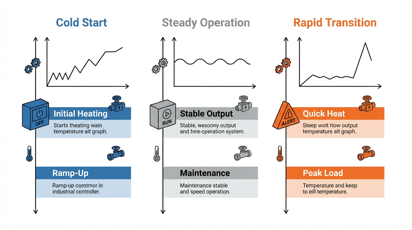
Finally, the operating range on the label does not specify whether the device can start cold at that temperature, or just continue operating once already warmed up. The ANSI discussion of IEC 60068 change‑of‑temperature testing emphasizes that cold starts, rapid shifts between warm and cold, and condensation can all drive very different failure modes than smooth operation at a steady temperature. A serious wide‑range design and qualification program distinguishes between cold‑start behavior, steady operation, and rapid transitions, even if they are all lumped into one line on the brochure.
How Temperature and Humidity Actually Damage Industrial Electronics
To decide whether a -40°F to 158°F rating is credible, it helps to understand how temperature and humidity degrade electronics over time. Several sources converge on the same message: both heat and cold are dangerous in different ways, and humidity often turns a manageable situation into a failure.
An analysis from Allometrics notes that electronic devices generally perform better and last longer in cooler environments, but excessive cold is far from harmless. High temperatures accelerate chemical and physical processes inside components. Material changes in dielectrics and insulators, impurity diffusion, and reactions at metal interfaces increase leakage current and reduce insulation. Fortec US, writing about heat in electronics, ties this directly to phenomena such as thermal runaway, in which rising temperature causes devices to dissipate more heat than they can shed, leading to catastrophic failure or even fire.
The same heat also attacks passive components. Resistors and capacitors drift from their nominal values, and electrolytic capacitors in particular suffer when the internal electrolyte gradually dries out under high temperature, as described by Rika Sensors and LISUN. The result is rising equivalent series resistance, declining capacitance, and eventual power‑supply instability, noise, and outright failure. A reliability overview notes that a useful rule of thumb for many components is that failure rates can roughly double for every moderate temperature increase, a familiar Arrhenius‑type relationship.
Cold introduces a different set of problems. Allometrics highlights that extreme cold can cause equipment to shut down to protect internal parts. Mechanical components contract, increasing stress on moving parts. Displays, motors, and disk drives can fail to start or operate normally at low ambient temperatures. Perhaps the most insidious effect appears when equipment is moved from a cold environment into a warm, humid space. Condensation forms on and inside the electronics; Rika Sensors and LISUN both emphasize that this moisture can lead to short circuits, corrosion, and long‑term reliability problems if it penetrates into boards, connectors, and solder joints.
Humidity by itself is a major reliability driver. High humidity allows moisture to enter porous packaging, printed circuit board materials, and tiny gaps under surface‑mount parts. Over time, this supports corrosion, lowers insulation resistance, and promotes leakage currents and dendritic growth on board surfaces. LISUN stresses that combined temperature–humidity cycling rapidly accelerates crack formation, material fatigue, and a range of degradation mechanisms. At the opposite extreme, very low humidity increases the risk of electrostatic discharge events that can cause immediate or latent damage.
In short, the -40°F to 158°F line is only part of the story.

Without attention to humidity, condensation, and thermal cycling, hardware that technically meets the temperature range can still fail prematurely in real plants and outdoor installations.
Standards That Underpin Wide Temperature Range Claims
Wide‑temperature specifications are only as good as the test methods behind them. In industrial automation, those test methods are heavily influenced by the IEC 60068 family and a cluster of sector‑specific standards in automotive, aerospace, telecom, and military applications.
A concise overview from ANSI describes IEC 60068‑2‑14, which defines standardized methods for change‑of‑temperature tests on electronic equipment and components. Unlike simple high‑temperature or low‑temperature soak tests, IEC 60068‑2‑14 focuses on the effect of transitions between temperatures. It allows both single and repeated temperature changes and sets parameters such as the high and low conditioning temperatures, dwell times, rate of temperature change, number of cycles, and how heat is transferred into and out of the test specimen. The standard explicitly notes that internal parts change temperature more slowly than external surfaces, particularly when equipment is powered off, which has to be considered when defining test profiles and measurement points.
Complementing 60068‑2‑14 are IEC cold and dry‑heat standards, referenced in the ANSI discussion as IEC 60068‑2‑1 and IEC 60068‑2‑2. Together, these let you qualify both extreme endpoints of the stated operating range and the transitions between them. A practical recommendation from ANSI is to pair change‑of‑temperature tests with the dedicated cold and heat tests in order to achieve a complete thermal qualification rather than focusing on just one aspect.
A broader article on IEC 60068 environmental testing from Cybernet Manufacturing explains how the family of standards is structured. IEC 60068‑1 sets general terminology and test philosophy, IEC 60068‑2 contains the specific environmental tests and their severity levels, and IEC 60068‑3 offers supporting documentation and guidance. Within IEC 60068‑2, there are test categories for extreme temperatures, shock and vibration, and hostile environments such as salt mist, pressure extremes, and water ingress. An extended salt‑fog test example described there involves alternating salt spray and humid air over weeks to verify corrosion resistance.
Thermal and environmental testing in practice is rarely limited to temperature alone. AMREP, writing on thermal and environmental test methods, notes that electronics expected to survive harsh conditions are typically exposed to a combination of thermal cycling or shock, high‑temperature operating life, burn‑in, humidity, vibration, drop or shock, altitude, and corrosion tests. For instance, a typical thermal cycling profile might swing between roughly -67°F and 257°F for hundreds of cycles, with dwell times of ten to thirty minutes at each extreme, specifically to prevent cracks and solder joint failures. High‑temperature operating life tests keep a product running at around 257°F for hundreds or thousands of hours to reveal long‑term degradation under power. Burn‑in tests often run assemblies at ambient temperatures between about 122°F and 257°F for one to seven days to weed out early‑life failures.
Humidity tests are commonly performed at 85–95 percent relative humidity and temperatures ranging from about 77°F up to 140°F, for durations from a couple of days to several weeks, in order to accelerate moisture‑related failure mechanisms. AMREP also mentions vibration tests across 5–2000 Hz, drop tests from heights of roughly 1.6 ft up to 4.9 ft, altitude tests up to around 50,000 ft, and salt fog and dust ingress tests using standardized test dust. All of these are tailored depending on whether the product is for automotive, aerospace, military, marine, or construction applications.
Because component temperatures determine reliability, JEDEC 51 standards, referenced in an electronics testing article from Russells Technical Products, define how to measure package temperatures and characterize thermal performance under various conditions. That component‑level understanding feeds back into board and enclosure‑level modeling.
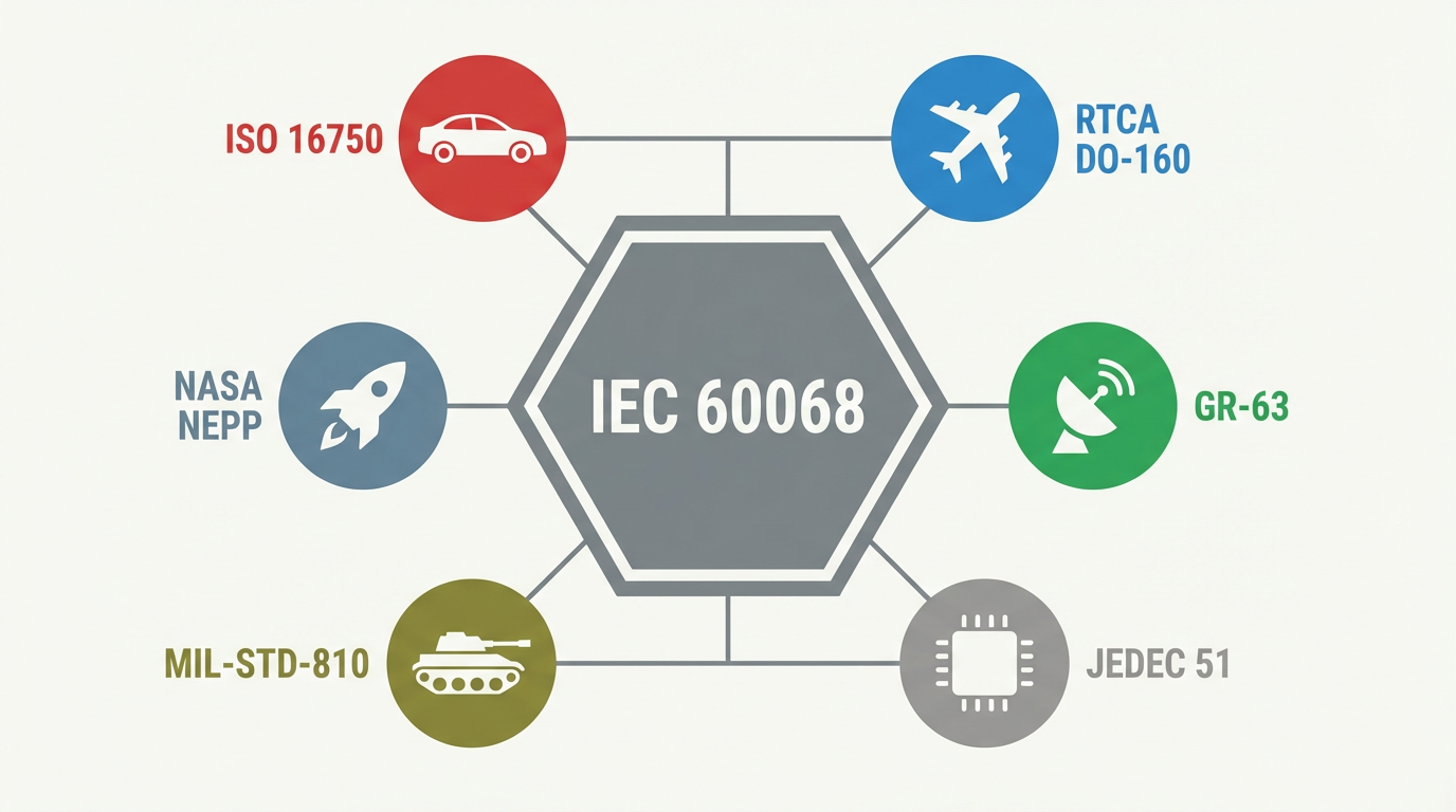
Sector‑specific standards further refine expectations. AMREP points to ISO 16750 for automotive electrical and electronic equipment, RTCA DO‑160 for airborne equipment, and GR‑63 for telecom hardware, while a high‑temperature electronics article from Analog Devices notes that NASA and similar agencies rely on their own guidelines for extreme environments. NASA’s NEPP program, summarized in a COTS parts memo, emphasizes that when commercial parts are used beyond their manufacturer’s temperature ratings, behavior can deviate significantly, and each such use should be treated almost as its own development program, with detailed characterization and conservative margins.
The upshot is that a wide‑temperature specification grounded in IEC 60068 testing and the relevant sector standards has a very different meaning from one that is simply extrapolated from room‑temperature performance.
A brief overview of how some of these standards relate to wide‑temperature operation is shown below.
| Standard or family | Primary focus | Relevance to -40°F to 158°F operation | Source context |
|---|---|---|---|
| IEC 60068‑2‑14 | Change of temperature tests | Defines how to cycle between temperatures, addressing rapid transitions, dwell times, and internal vs external temperature behavior | ANSI discussion of IEC 60068‑2‑14 |
| IEC 60068‑2‑1 / 2‑2 | Cold and dry heat tests | Establishes performance at low and high extremes, complementing change‑of‑temperature tests | ANSI and Cybernet summaries |
| IEC 60068‑2‑30 / 2‑52 | Damp heat and salt fog | Adds humidity and corrosion stresses relevant to real industrial environments | Cybernet Manufacturing article |
| IEC 60068 family overall | Environmental testing framework | Provides a consistent way to claim environmental robustness across countries and markets | Cybernet Manufacturing article |
| JEDEC 51 series | Thermal measurement of components | Guides how to characterize component package temperatures and thermal resistance | Russells Technical Products article |
| ISO 16750, RTCA DO‑160, GR‑63 | Automotive, airborne, telecom environments | Map thermal, vibration, and other stresses to specific use cases beyond generic lab conditions | AMREP test overview |
| MIL‑STD‑810, MIL‑STD‑1540 | Military and aerospace environments | Define high‑level environmental test methods including temperature, vibration, and vacuum | AMREP and Russells discussions |
| NASA NEPP guidance | COTS parts beyond rated temperatures | Warns against extrapolating behavior outside published temperature ranges; recommends deep characterization | NASA NEPP COTS extreme‑temperature memo |
Component Temperature Grades and Their Implications
The wide‑temperature promise on an industrial controller or panel PC is anchored in the parts inside it. Online component guidance on temperature ratings points out that commercial‑grade parts are generally designed around an ambient range of roughly 32°F to 158°F, industrial‑grade parts around -40°F to 185°F, and automotive parts from about -40°F to 257°F or higher.
In a -40°F to 158°F industrial design, using mostly commercial‑grade components leaves minimal margin at the upper end. The same guidance notes that operating outside a component’s rated range risks parametric drift or even permanent damage. Semiconductor devices see rising leakage current and shifts in thresholds and gain as temperature climbs; resistors and thermistors change resistance; capacitors, especially electrolytics, exhibit strong temperature dependence; oscillators drift; and batteries lose capacity or age prematurely.
By contrast, using industrial or automotive‑grade parts provides more headroom. NASA NEPP observations on extreme‑temperature COTS behavior show that parts can sometimes function beyond their data sheet limits, but with large parameter shifts and weakened margins. That should be an exception reserved for missions where no alternatives exist and where extensive characterization is justified. For industrial automation, the practical takeaway is simpler: if you want credible -40°F to 158°F operation, do not rely on a commercial sensor or regulator that is only rated to 158°F and then park it next to a power MOSFET whose case runs far hotter.

Designing Hardware That Survives -40°F to 158°F
Once the environment and standards are understood, the design challenge is to build hardware that genuinely survives, and keeps performing, across the range. Several technical themes recur in the harsh‑environment design literature.
Materials, Substrates, and Interconnects
An article on extreme‑environment electronics from Arshon emphasizes that material choice is foundational. Standard FR‑4 can be sufficient for moderate industrial conditions, but in more demanding environments engineers often move to polyimide laminates, which can tolerate temperatures up to roughly 500°F, PTFE‑based RF laminates, or ceramic substrates such as alumina or aluminum nitride for their high thermal conductivity and dimensional stability. While these extremes go well beyond a 158°F spec, they illustrate how substrate choice can add margin when parts of the system run hotter than the surrounding air.
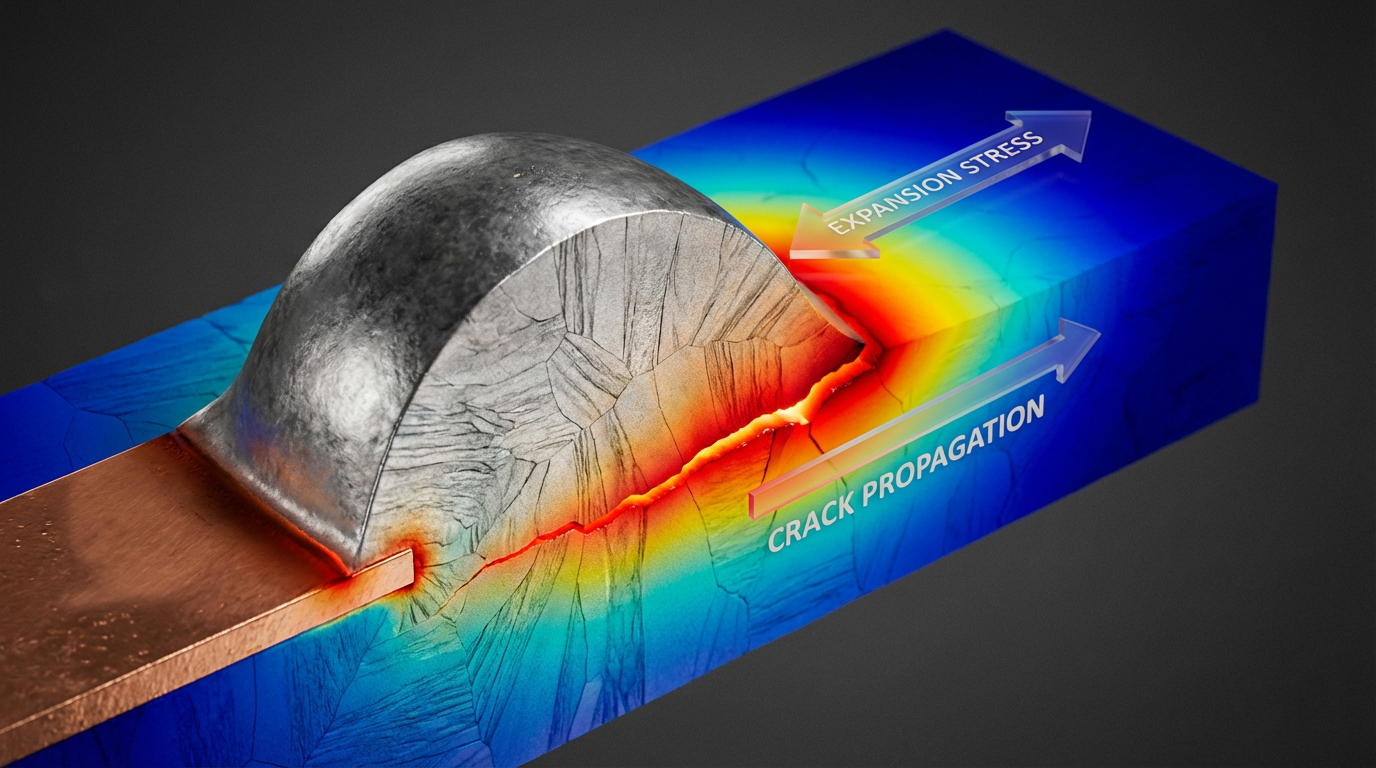
Metallurgy and interconnects also matter. Arshon describes the use of solder alloys with higher melting points, gold or silver finishes, and nickel plating to improve corrosion resistance and act as diffusion barriers. NASA NEPP notes that at extreme temperatures, package cracking, delamination from coefficient‑of‑thermal‑expansion mismatch, solder joint fatigue, and die or bond‑wire damage become serious risks. Even within the more modest industrial range, repeated thermal cycling between cold plant nights and hot daytime operation can fatigue solder joints and connectors, especially where materials expand at different rates.
A high‑temperature instrumentation amplifier design case from Analog Devices highlights the importance of wire‑bond metallurgy. Common gold‑wire to aluminum‑pad bonds can form brittle intermetallics and voids after prolonged high‑temperature exposure, while monometallic bonds with slower intermetallic growth show much better endurance. For standard industrial hardware, the key message is that packages and interconnect systems designed for elevated temperatures are much more tolerant of the stresses that occur near the top end of the -40°F to 158°F range, and even more so if the device occasionally experiences higher internal temperatures.
PCB Layout, Coatings, and Mechanical Robustness
PCB layout is more than just fitting traces between pins. Arshon and an article on designing electronics for harsh conditions from EWM Manufacturing both emphasize strategies such as thick copper planes, thermal vias, and copper pours under hot components to spread heat. Flexible or rigid‑flex sections can relieve mechanical strain, and careful spacing of high‑voltage traces helps prevent arcing and moisture‑driven leakage.
Conformal coatings are widely recommended for industrial environments. The harsh‑conditions article categorizes coatings as urethane, acrylic, epoxy, silicone, and parylene, each with clear pros and cons. Silicone coatings are commonly chosen for electronics exposed to extreme temperature ranges because they offer excellent humidity and corrosion resistance along with strong adhesion. Parylene coatings, deposited as thin, uniform films, offer some of the best extreme‑temperature and solvent resistance among common options and very high dielectric strength, albeit at the cost of removal difficulty and specialized deposition equipment. Selecting an appropriate coating helps protect against condensation events described by Allometrics and Rika Sensors, particularly when equipment experiences rapid temperature changes.
Internal mechanical robustness also contributes. Rugged‑device design examples from EWM Manufacturing note the use of solid‑state drives instead of rotating media, internal stiffeners to prevent PCB flexing, energy‑absorbing cases and bumpers, and chemically strengthened display glass. While these are often discussed for handhelds and tablets, the same thinking applies to panel PCs and machine‑mounted HMIs that must survive vibration and thermal stress on production equipment.
Power Supplies and Thermal Management
Power systems feel temperature stress early, as Advanced Conversion Technology (ACT) describes in its discussion of power system reliability. High temperatures accelerate degradation of capacitors and other components and can loosen mechanical connections, shortening supply life. Operating a power supply outside its specified ambient range forces derating, meaning that the available load must be reduced to keep internals within their limits. In low‑temperature environments, ACT points out that performance issues such as increased output voltage ripple, incomplete regulation, startup failures, and seal failures in electrolytic capacitors can occur.
Thermal management articles from Fortec US, Diabatix, Modus Advanced, and US Electronics collectively converge on the same practices. Heat sinks and fans remain the frontline tools for moving heat away from components. Heat sinks, often aluminum or copper with fins or pins, expand surface area to encourage convection. Fans and blowers enhance airflow and allow more compact designs but introduce noise, dust transport, and mechanical wear.
Thermal interface materials such as pads, pastes, phase‑change materials, adhesives, and gap fillers reduce thermal resistance between components and their heat spreaders or enclosures. Modus Advanced notes that pads and gap fillers can offer moderate thermal conductivity with low assembly complexity, while thermal adhesives and higher‑performance materials deliver better thermal paths but demand precise dispensing and curing controls.
Airflow management is just as critical as the choice of materials. Diabatix emphasizes the need to design enclosures and venting so that cool air reaches hot spots and hot air can escape, with minimal obstructions. In higher‑power or densely packed systems, liquid cooling may be appropriate, using water or specialized coolants circulating through channels or heat pipes to transport heat away from components, although this is more common in servers, EV power electronics, and specialized high‑power controls than in ordinary PLCs.
The best designs do not wait until hardware is built before considering temperature.
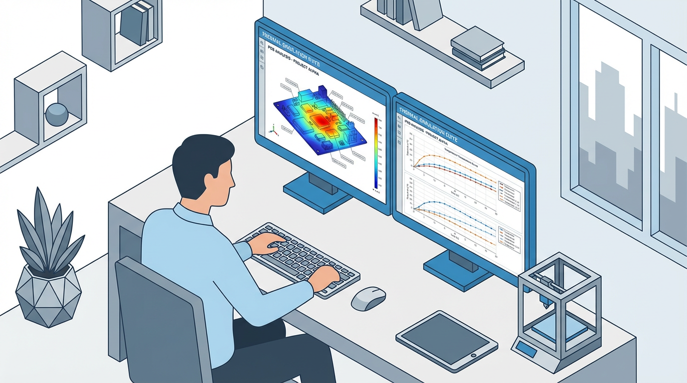
Siemens EDA, in a guide on component temperature prediction, stresses the role of pre‑production thermal simulations. Accurately predicting component temperatures during operating cycles, modeling key heat sources explicitly, and validating models with experiments build confidence that the hardware will meet its targets before anyone cuts metal on enclosures or installs units on a production line.
Derating and Circuit Techniques for Wide Temperature
Arshon and Analog Devices both highlight component derating as a central reliability tool. Rather than running parts at their maximum voltage, current, or temperature, designers choose parts with ratings well above the worst‑case stress. A typical practice is to use capacitors with voltage ratings at least fifty percent above nominal and to keep junction temperatures substantially below their data sheet limits. The online component guidance adds that staying within generous margins for voltage, current, and temperature reduces the risk of drift and premature failures.
For precision analog and mixed‑signal circuits that must operate accurately across wide temperature ranges, advanced circuit techniques matter. A chapter by Benjamin Blalock on wide‑temperature‑range circuit design describes a current reference architecture built from a proportional‑to‑absolute‑temperature voltage generator and a transconductor that converts that voltage to a reference current dominated by well‑controlled process parameters rather than by passive component tolerances. The point is not that every industrial controller needs that exact circuit, but that to keep measurement and actuation accurate across -40°F to 158°F, designers must model and compensate for temperature‑dependent phenomena such as threshold shifts, mobility changes, and noise.
Testing Strategy: Turning Specifications Into Reality
Design choices are only half the story. The other half is proving that your -40°F to 158°F claim is backed by credible testing and documentation.
AMREP’s environmental test workflow is a useful template. It begins with requirement analysis: understanding the actual environment, regulatory requirements, and reliability targets. For an industrial controller, that might mean clarifying whether the unit is mounted in a sealed panel, near hot process equipment, in a dusty warehouse, or on a vehicle, and identifying any customer‑mandated standards such as IEC 60068 or MIL‑STD‑810.
Next comes test planning, where teams select standards and methods, define parameters such as temperature ranges, ramp rates, dwell times, number of cycles, and sample sizes, and decide which tests will be done at the component, board, and system levels. Russells Technical Products notes that this is also when engineers specify performance parameters for thermal chambers, including required temperature ranges, change rates, and humidity capabilities, and consider the size and mass of devices under test and the available lab space and utilities.
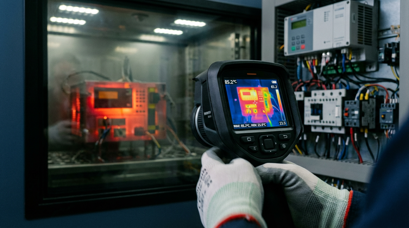
Sample preparation follows, including labeling, sensor placement, and pre‑test checks. During test execution, data loggers and software monitor temperatures, humidities, voltages, and system responses continuously. Thermal imaging, described in the AMREP article, is often used to identify hot spots under idle, maximum load, and transient conditions, using infrared cameras that can capture temperature distributions over a wide range.
The final stage is reporting and feedback. AMREP emphasizes detailed documentation, both for compliance and for engineering improvement. Failures observed during thermal cycling, burn‑in, or humidity tests feed directly into design revisions, supplier quality actions, and updates to derating guidelines. Megalab and other environmental labs stress traceability and clear pass/fail criteria so that when something does go wrong in the field, the organization can compare real‑world conditions to what was actually tested.
Future‑looking trends mentioned by AMREP, such as AI‑driven analysis and digital twins, promise to improve the fidelity of test planning and failure prediction. But the fundamentals remain the same: realistic test profiles, adequate sample sizes, careful monitoring, and honest reporting.
Pros and Cons of Specifying Wide Temperature Range Hardware
For an end user or OEM, choosing hardware rated to -40°F to 158°F brings both advantages and trade‑offs.
On the plus side, a wider operating band offers safety margin against unexpected conditions. Heat buildup inside a control panel, occasional loss of HVAC in a plant area, or colder‑than‑expected outdoor temperatures are less likely to push equipment beyond its limits. Relying on hardware tested over wide temperature and environmental conditions, according to the IEC 60068 family or similar standards, reduces the risk of sudden failures that can shut down production lines or compromise safety systems. Cybernet Manufacturing, for example, argues that IEC 60068 testing of industrial computers is effectively mandatory when systems are mounted next to vibrating machines or in vehicles.
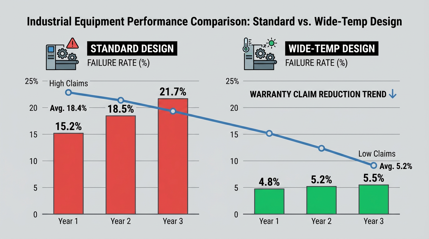
Robust thermal design also pays off in reliability and lifetime. US Electronics and Modus Advanced both describe thermal management as a primary design consideration, not a late‑stage fix, precisely because excessive temperature accelerates wear‑out and heat‑induced faults. Meeting the wide‑temperature spec with margin can reduce field failure rates and warranty claims.
On the downside, wider temperature capability usually costs more. Automotive‑ or industrial‑grade components are more expensive than commercial ones. Higher‑temperature substrates, more capable coatings, and larger heat sinks or more powerful fans add material cost and complexity. Russells Technical Products observes that large walk‑in or drive‑in thermal chambers used for full‑system testing can have long lead times and require significant floor space and infrastructure, which must be factored into project schedules.
Moreover, not every application truly needs the full -40°F to 158°F range. ANSI’s observation that many general‑purpose electronics should ideally stay near room temperature reminds us that over‑specifying can be wasteful. The practical approach, especially from a systems integrator’s viewpoint, is to match the hardware’s rating to the worst‑case credible environment with a sensible margin, not to chase the widest possible number on the data sheet.
Practical Guidance for Specifiers, Integrators, and Plant Engineers
When you are responsible for specifying or integrating industrial control hardware, there are several pragmatic questions and checks that help separate marketing from engineering.
First, clarify your real environment, including temperature, humidity, and their variability. Facility‑level work, such as the temperature mapping recommended by Allometrics, can reveal hot and cold spots caused by weather, building layout, air circulation, and product load. If a “climate‑controlled” space has corners that regularly reach well above 95°F or areas where cold air pools near floor‑level cabinets, that information should influence your hardware choices.
Second, look beyond the nominal operating range and ask how the vendor tested for it. Did they perform IEC 60068‑2‑14 change‑of‑temperature cycles, cold and dry‑heat soaks, and humidity tests, or simply extrapolate? Do they reference JEDEC 51 thermal characterization for critical components? Have they considered combined environments, such as temperature and vibration together, as in MIL‑STD‑810 methods?
Third, pay attention to humidity and condensation. A wide temperature rating does not automatically mean the device is safe against high humidity or rapid transitions that drive condensation. Ask about conformal coatings, sealing strategies, and any IEC 60068 humidity or salt‑fog tests that were run. The harsh‑conditions design literature makes it clear that coating choice and enclosure sealing can be as important as raw temperature capability.
Fourth, do not ignore power supplies and external power quality. ACT’s analysis highlights that overvoltage, line noise, and thermal stress combine to damage supplies. Selecting power units explicitly rated for your full temperature range and environmental conditions and planning for adequate cooling and monitoring prevents many hard‑to‑diagnose issues.
Finally, build temperature and environmental considerations into your commissioning and maintenance practices. Use temperature and humidity monitoring inside panels and equipment rooms, not just in building automation systems. Follow the climate‑control and filtration best practices that Allometrics outlines, including proper air circulation and filter maintenance, so that the wide‑temperature‑rated hardware you purchased is not pushed beyond its limits by avoidable environmental neglect.
Short FAQ on Wide Temperature Range Specifications
Does a -40°F to 158°F operating spec guarantee my system will work anywhere in that range?
It guarantees that the manufacturer claims the device will meet its performance specifications when the surrounding air is between those temperatures, under the conditions they tested. As ANSI and IEC 60068 guidance make clear, details such as cold starts, rapid temperature changes, humidity, and vibration can all influence behavior. Always ask how the spec was validated and how close your real environment is to the test profiles.
How does humidity interact with wide temperature ranges?
Humidity amplifies temperature‑driven risks. LISUN and Rika Sensors both show that high humidity leads to moisture ingress, corrosion, and leakage, while low humidity increases electrostatic discharge risk. Combined temperature–humidity cycling is especially damaging. If your environment involves high humidity or frequent transitions between cold and warm spaces, a wide‑temperature rating is necessary but not sufficient; you also need appropriate coatings, sealing, and humidity control.
Is it acceptable to run commercial‑grade parts up to their maximum 158°F rating in an industrial design?
NASA NEPP’s examination of COTS parts at extreme temperatures and the broader reliability literature warn against relying on components exactly at their limits. While parts may function beyond their data sheet ranges in some cases, behavior can shift significantly and unpredictably. For industrial control hardware where downtime and safety matter, it is wiser to use industrial‑ or automotive‑grade parts and keep actual operating temperatures well within their specified ranges, leveraging derating and robust thermal design.
In industrial automation, the line that says “-40°F to 158°F operating temperature” only earns trust when it is backed by thoughtful component selection, solid thermal and mechanical design, and rigorous IEC 60068‑style testing. When those pieces are in place, that one line on the data sheet becomes more than a sales promise; it becomes a reliable foundation for systems you are willing to sign your name under.
References
- https://nepp.nasa.gov/docs/tasks/075-EEE-Parts-Assurance/NEPP-TM-2021-Boomer-COTS-EEE-Parts-Under-Extreme-Temperatures-20210018153.pdf
- https://blog.ansi.org/ansi/iec-60068-2-14-ed-7-0-b-2023-temperature-testing/
- https://www.rikasensor.com/the-impact-of-temperature-and-humidity-on-electronics.html
- https://www.us-electronics.com/thermal-management-in-electronics-trends-and-best-practices
- https://allometrics.com/the-effects-of-temperature-on-electronic-devices/
- https://amrepinspect.com/blog/thermal-environmental-testing-in-electronics
- https://www.diabatix.com/blog/thermal-management-of-electronics-guide-ensuring-performance-and-reliability
- https://news.ewmfg.com/blog/designing-electronics-for-harsh-conditions
- https://fortec.us/how-heat-affects-your-electronics-i-apollo-display-technologies/
- https://russells-tech.com/understanding-thermal-test-chambers-and-their-uses/
Keep your system in play!
Top Media Coverage
Categories


Related Products
-
 Control ModuleManufacturer: ABB
 -
Exciter Power Supply ModuleManufacturer: General Electric
-
Excitation Control BoardManufacturer: General Electric
-
Printed Circuit BoardManufacturer: VAISALA
-
Exciter Ground Detector ModuleManufacturer: General Electric
-
MotherboardManufacturer: MTU
-
Control UnitManufacturer: Haver&boecker
-
EXCHANGE CONTROL BOARDManufacturer: INDUSTRONIC
-
PCIe Bus Interface ModuleManufacturer: ALPHI
-
Integrated Digital PCB Board ControllerManufacturer: AMAT

Related articles Browse All
-
 amikong NewsSchneider Electric HMIGTO5310: A Powerful Touchscreen Panel for Industrial Automation2025-08-11 16:24:25Overview of the Schneider Electric HMIGTO5310 The Schneider Electric HMIGTO5310 is a high-performance Magelis GTO touchscreen panel designed for industrial automation and infrastructure applications. With a 10.4" TFT LCD display and 640 x 480 VGA resolution, this HMI delivers crisp, clear visu...
 -
 BlogImplementing Vision Systems for Industrial Robots: Enhancing Precision and Automation2025-08-12 11:26:54Industrial robots gain powerful new abilities through vision systems. These systems give robots the sense of sight, so they can understand and react to what is around them. So, robots can perform complex tasks with greater accuracy and flexibility. Automation in manufacturing reaches a new level of ...
 -
 BlogOptimizing PM Schedules Data-Driven Approaches to Preventative Maintenance2025-08-21 18:08:33Moving away from fixed maintenance schedules is a significant operational shift. Companies now use data to guide their maintenance efforts. This change leads to greater efficiency and equipment reliability. The goal is to perform the right task at the right time, based on real information, not just ...


- Q&A
- Policies How to order Part status information Shipping Method Return Policy Warranty Policy Payment Terms
- Asset Recovery
- We Buy Your Equipment. Industry Cases Amikong News Technical Resources Why choose us
- ADDRESS
-
 32D UNITS,GUOMAO BUILDING,NO 388 HUBIN SOUTH ROAD,SIMING DISTRICT,XIAMEN
Leave Your Comment