
-
Please try to be as accurate as possible with your search.
-
We can quote you on 1000s of specialist parts, even if they are not listed on our website.
-
We can't find any results for “”.
Best Practice for Cable Routing in Control Panels: Professional Standards
As a systems integrator who has commissioned and serviced hundreds of panels in production environments, I judge cable routing by a simple yardstick: it must keep machines running and make the next change safe and fast. A tidy panel that is a nightmare to trace is not a success, and a serviceable panel that looks chaotic will not pass audits or inspire confidence. The best practice sits in the middle, guided by standards and reinforced by field‑tested habits.
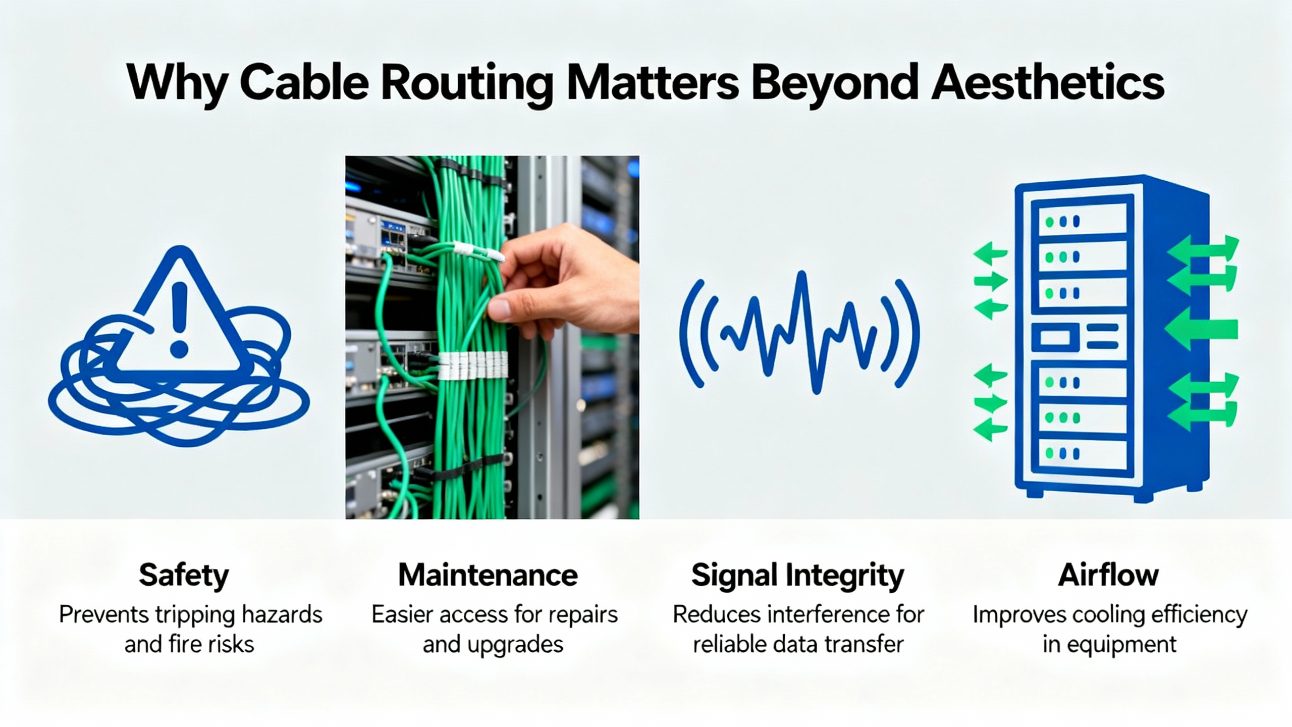
Why Cable Routing Matters Beyond Aesthetics
Inside a control panel, routing is a reliability function, not decoration. Consistent pathways protect insulation from abrasion, keep bend radii reasonable, preserve airflow, and position shields and grounds where they actually control noise. The practical difference shows up when an I/O card drops a channel during a critical shift. With disciplined routing and labeling, a technician can locate the conductor, evaluate the termination, and recover production quickly. Without it, the same fault becomes a protracted hunt.
Experience in broadcast racks and shop‑floor enclosures points to two goals that occasionally conflict: visual order and traceability. Community practitioners have noted the same pattern in other domains: sleek looks are easy to achieve with dense bundling and closed looms, but that often slows modifications and hides branch points. Reusable hook‑and‑loop straps and clear, consistent labels on both ends land in the sweet spot, because they enable changes without cutting hardware and they make the path visible end‑to‑end. This principle holds whether you are dressing a PLC cabinet or a server rack.
Codes and Standards You Actually Work With
Industrial control panels at 600 V and below are governed by NFPA 79, and the panel as an assembly sits under NEC Article 409. Those documents drive wire sizing, bend space, working clearances, and overcurrent protection choices. IEC 60204‑1 provides parallel guidance on safety of machinery and wiring practices used globally. For labeling and administration, ANSI/TIA‑606 provides a robust way to name conductors, devices, and terminations so technicians can trace circuits without insider knowledge. Product standards matter too: wiring ducts are covered by UL 1565, CSA C22.2, and IEC 61084‑2‑1, while installation practices tie back to NFPA 70 and CSA C22.1. Keep one more rule firmly in mind from NEC: maintain 3 ft of free space around active electrical equipment for safe access and service.
I do not attempt to reproduce standards language here. Instead, the sections that follow translate the intent of these documents into layout, routing, and verification moves that withstand audits and help crews do good work. Where I infer a practice from adjacent domains, I note that explicitly.

Plan the Layout Before You Pull a Single Conductor
Good routing starts on paper. Use CAD to place wireways where cables want to travel: down spine ducts near the enclosure corners, across short duct runs at device rows, and into vertical risers aligned with terminal blocks. Avoid diagonal runs and crisscrossing. Reserve bend space at every device and terminal, and allow room under the main wireway to coil service slack where it is accessible but not interfering with devices. Keep flexible conduits pitched so condensation drains away from fittings, not toward electronics.
Signal segregation is the backbone of planning. Group and route by the nature of the circuit rather than by convenience. A practical way to communicate that plan to panel builders and service techs is to classify circuits by their interference potential and sensitivity, then keep those classes physically separate as they move through ducts and raceways.
| Signal Class | Typical Examples | Sensitivity | Routing and Shielding Notes |
|---|---|---|---|
| Class 1 | Mains feeders, VFD inputs, power converters with high di/dt | Low sensitivity, high interference | Route in dedicated duct or conduit; avoid proximity to sensitive runs; bond metallic pathways for EMC; terminate shields appropriately if present |
| Class 2 | Relay contacts and general control outputs | Low to moderate sensitivity | Keep clear of sensitive analog and high‑speed signals; share pathways with Class 1 only if barriers or shielding are present |
| Class 3 | Digital I/O, PLC backplanes, low‑voltage logic | Moderate sensitivity | Segregate from Class 1 and 2; cross power at right angles; keep leads short near terminations |
| Class 4 | Analog inputs/outputs and instrumentation | High sensitivity | Route separately and away from power; maintain shield continuity and single‑point grounding as designed; avoid running parallel to Class 1 for long distances |
This scheme, widely recommended in control‑panel guidance from sources such as c3controls and industrial wiring guides, prevents radiated and coupled interference from eroding signal integrity. It also gives builders a clear rule to follow at every bend, tie point, and terminal.

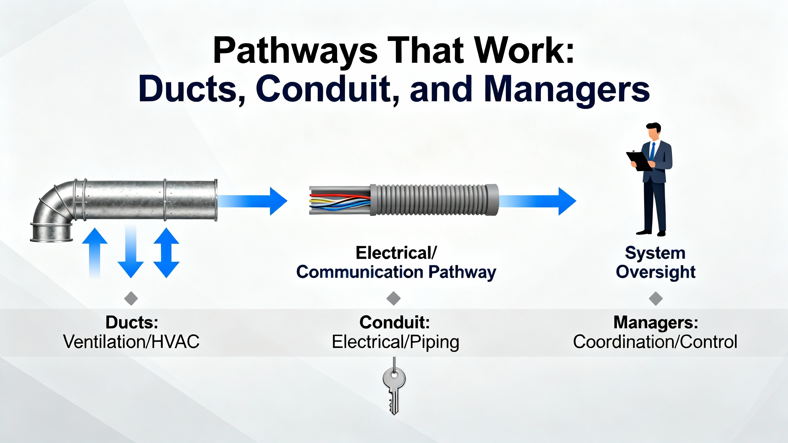
Pathways That Work: Ducts, Conduit, and Managers
Inside the enclosure, slotted wiring duct is the workhorse, while solid‑wall duct has a place when frequent access is not required. Narrow‑slot sections suit small‑diameter conductors and dense terminations; wide‑slot sections hold mixed gauges and provide better support around corners. Metal trunking and metallic conduit add useful shielding and bonding points in noisy environments.
Outside the enclosure, or for entries and inter‑panel runs, select conduit or cable trays that match the environment. Liquid‑tight metal conduit resists liquids while providing a bonded path; plastic conduits offer flexibility and crush recovery. Use cord grips and grommets at entries sized to the panel hole and thickness to prevent edge abrasion; select materials to suit temperature and chemical exposure. Component suppliers such as Essentra and Brady publish material temperature ranges and UL flammability ratings that help narrow the choices; prioritize parts that meet UL and IP ratings appropriate to the installation.
A design habit from high‑density compute racks also pays dividends in panels: preserve spare capacity in your ducts and trays so you can add circuits later without tearing out existing runs. In racks, 30 to 40 percent spare pathway space is a common target; by analogy, reserving about one‑third spare in panel wireways keeps future work civil while preserving airflow. This is an inference from data center practice rather than a specific panel standard, and I rate the guidance as moderate confidence.
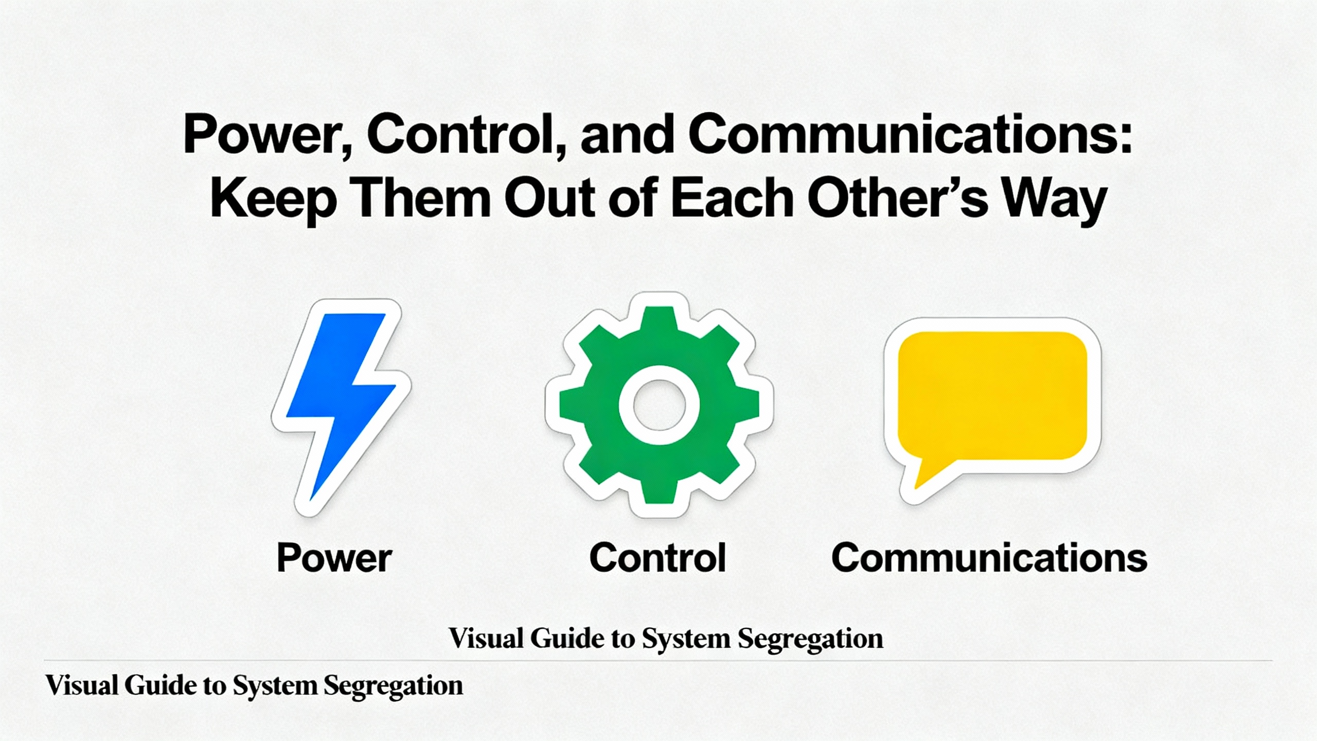
Power, Control, and Communications: Keep Them Out of Each Other’s Way
Electromagnetic compatibility is earned in the layout. Run protective earth conductors close to their associated live conductors to minimize loop area and impedance. Where you bring shields into a termination, secure them to prevent fraying and either bond per the design or trim and sleeve them back if not used. Do not tin stranded conductors before landing them on screw clamps, as solder creep can loosen terminations under heat; use bootlace ferrules where the terminal lacks strand retention. Keep high‑power motor feeders and switching supplies physically separate from low‑voltage signals. When crossings are unavoidable, cross at right angles and do not parallel the runs for long distances in shared duct fingers.
At the device level, route internal and external conductors so they do not cross over the device terminals. This simple pattern minimizes stray whiskers, speeds probing, and keeps strain away from the termination screws. Add a drip loop or route so any moisture drains away from fittings, particularly near gland plates and flex entries.
Terminations and Strain Relief: Do Them Once, Do Them Right
Most reliability problems in panels still come from loose, misapplied, or stressed terminations. Tighten screw and nut‑and‑bolt terminals to manufacturer torque and then perform a physical pull test on every connection. For spring‑type connectors, confirm full insertion and that the conductor cannot be withdrawn without a tool. Support multicore cable terminations so the cable jacket takes the strain, not the individual conductors, and leave modest service loops at connectors to allow maintenance without tugging on a tight span. A short slack reserve under the nearest wireway cover keeps the loop available and out of sight.
Crimp terminations with quality dies and ferrules sized to the wire and block. Prefer mechanical crimping and bootlace ferrules over solder on terminals not designed for solder. Where vibration is present, barrier blocks with ring or spade terminals and proper hardware stackups prevent loosening; this approach is widely used on equipment expected to live with shock and vibration. Field teams supporting mobile and competition robots have validated a simple truth that also applies in industry: shock‑mounting sensitive devices and verifying connector seating, ferrule quality, and strain relief prevent intermittent drops that are otherwise maddening to chase.
Hook‑and‑loop straps deserve their reputation. They secure bundles without crushing the insulation or deforming the dielectric around data pairs, and they allow quick rework when circuits change. Single‑use zip ties still have a place for fixed strain‑relief moves or safety lockouts, but they should not be your main bundling method in serviceable ducts. A common failure mode in neat‑looking builds is the closed wraparound loom with periodic exit holes; it hides branches and forces excessive manipulation during changes. Simple bundling with visible branches and disciplined labeling usually beats such looms for long‑term serviceability.
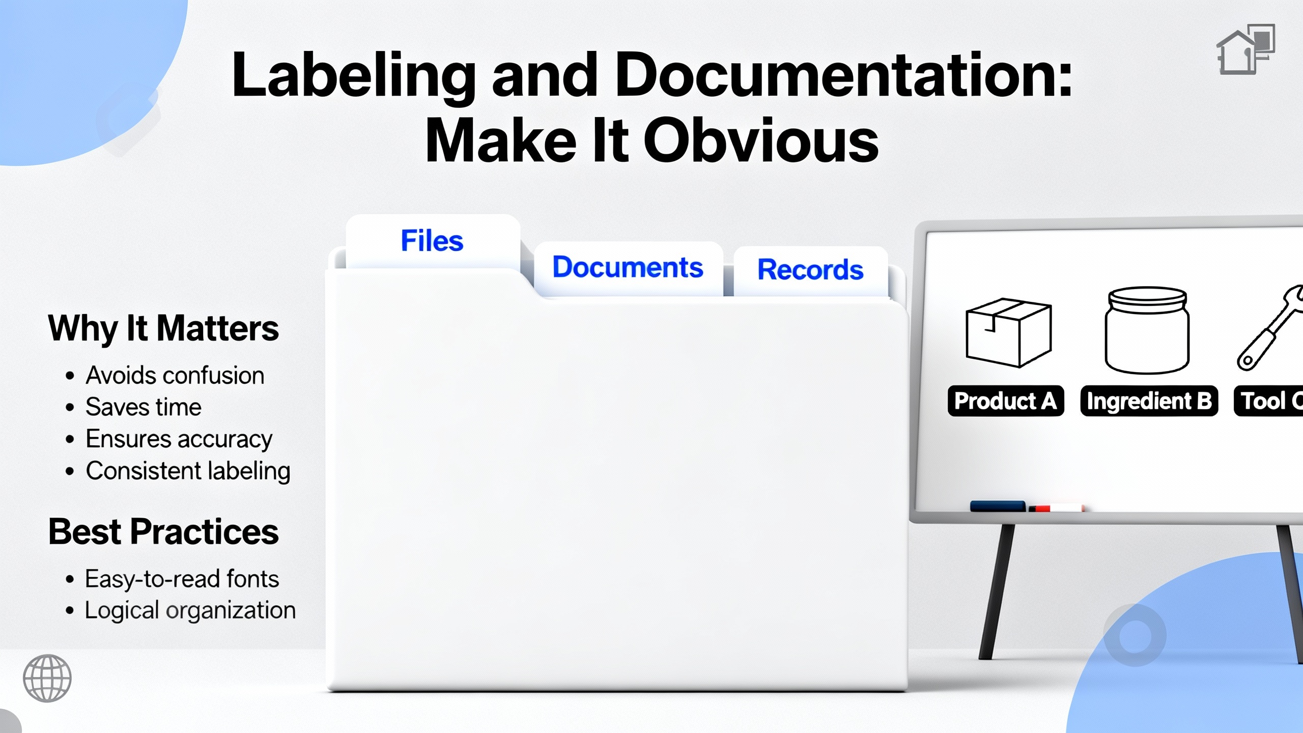
Labeling and Documentation: Make It Obvious
A good panel tells its own story. Label both ends of every cable with durable markers whose format your team can read in low light. Add terminal markers that match the drawings, and keep the drawing set updated when changes are made. Use color coding with purpose and document what the colors mean in the panel door pocket. ANSI/TIA‑606 gives a framework for naming pathways, devices, and terminations across a facility so technicians do not need local lore to interpret a label. For heavily patched systems, map ports to channels in a simple table and keep that map current. A laminated one‑page cable map taped inside the door is still one of the highest value artifacts in the whole enclosure.
Ducts and Terminal Blocks: Definitions, Choices, Pros and Cons
Choosing the right routing and termination components reduces time at the bench and in the field. Slotted wiring duct is a rigid pathway inside the enclosure with breakable fingers that let conductors enter and exit along the run; it is the default for accessible control wiring. Narrow slots favor small‑diameter conductors; wide slots better support mixed gauges and frequent re‑routing. Solid‑wall duct lacks slots and suits runs that rarely change. Trunking made of metal can improve EMC by providing a bonded, shielded path around noisy conductors.
Terminal blocks are insulated modular connectors used to join circuits and organize wiring. Device families include fuse‑holder blocks for localized protection, ground circuit blocks for structured grounding, I/O and sensor blocks for distributed terminations, thermocouple blocks with metallurgy matched to leads, distribution blocks for power branching, and disconnect blocks that incorporate a lever or knife for isolation. Structures can be single‑level pass‑through, dual‑level, or three‑level to save rail space. Mount them on DIN rail where possible for modularity, and choose termination mechanics that match your wires, tools, and environment.
| Termination Type | Best Use Case | Strengths | Considerations |
|---|---|---|---|
| Screw clamp | Broad range of conductors and sizes | Familiar, strong clamping, wide availability | Requires torque control and periodic verification |
| Spring clamp | Smaller wires, quick assembly | Vibration resistant, fast to land | Tooling and technique differences; verify full insertion |
| Insulation displacement (IDC) | Panelized, high‑volume terminations | Speed in standardized builds | Wire and insulation must match spec; not for frequent rework |
| Push‑in with ferrule | Fast assembly with prepared ends | Secure connection, reduced tool use | Requires ferrules sized to wire; plan tooling |
| Barrier with ring/spade | High vibration environments | Mechanical security, clear inspection | More parts per termination; hardware stack needs care |
These choices and behaviors are detailed in vendor white papers from sources such as c3controls, with standards alignment for UL, CSA, and IEC product families.
Cable Accessories that Prevent Rework
The humble parts at panel entries and along routes pay back their cost quickly. Grommets protect edges where conductors pass through sheet metal; choose EPDM or TPR for rugged outdoor or oil‑rich environments and ensure the grommet fits the hole and panel thickness. Bushings and cord grips provide strain relief and protect against pull‑out at entries. Horizontal and vertical cable managers, lacing bars, and clamps define cable routes and keep bundles away from moving parts or hinge pinch points. When you need to shield paths or enforce separation, metallic conduit and trunking offer grounding and EMI control that plastic cannot. Component publishers such as Essentra and Brady maintain catalogs and selection guides with material properties and ratings in Fahrenheit, helping you align part choice with enclosure environment.

Slack, Bend Radius, and Thermal Behavior
Slack is not laziness; it is insurance. Leave small, deliberate service loops at connectors and coils of spare under wireway covers where they are protected. That slack allows device swaps and terminal block maintenance without straining conductors. Maintain bend radius consistent with manufacturer data. When manufacturer guidance is absent, a conservative practice adopted from high‑speed cabling work is to keep bends at or above roughly ten times the cable’s outer diameter for copper, and to be even more cautious with fiber. This is an inference from data‑center guidance rather than a control‑panel‑specific standard; I rate it as moderate confidence. Bundles impede airflow and trap heat around power electronics, so plan cable runs to preserve convection paths and avoid draping over heat‑sensitive devices. If in doubt, feel for hotspots after an hour of operation and adjust pathways or bundling to open air channels.
Workflow, QC, and Field Verification
A wiring checklist is not bureaucracy; it is how you ship panels that do not come back. Before energizing, pull‑test every conductor, check that no exposed whiskers protrude beyond clamps, and verify that screw or nut‑and‑bolt terminations cannot be rotated by hand. Confirm that protective device fuses are fully seated and that snap‑in connectors lock mechanically. Torque record sheets and a quick photo set of the completed wiring runs give future maintainers a baseline to compare against.
The first days of operation reveal workmanship and routing issues that the bench did not. A pragmatic schedule is to re‑inspect terminations and mounts after the first duty cycle of vibration and thermal changes and then at regular intervals aligned with your maintenance calendar. This practice is borrowed from high‑vibration robotics and mobile applications, and while the environments differ, the idea of early re‑inspection catches weak interfaces before they cause downtime; I rate this guidance as moderate confidence for stationary panels.
Buying Tips That Save Money and Downtime
Buy wire in gauges and insulation ratings that match not just current draw but the bend space and termination geometry in your panel. Stranded conductors tolerate repeated movement and tight bends better than solid, which aligns with the flex life benefits called out by panel wiring vendors. Keep an inventory of varied lengths for internal jumpers and patching so you do not bury ducts in slack. Use a label printer with supplies rated for the enclosure temperature and chemical exposure; this way the identifiers you install today will still be legible when the next technician opens the door. Prefer hook‑and‑loop bundling for field‑modifiable runs, and save tie‑wraps for non‑serviceable applications or to lock critical strain relief where a one‑time, permanent clamp is desired. When choosing wiring duct, spend the extra dollars on stiffer, well‑finished product; it maintains finger integrity over years of additions and removals and resists cracking under maintenance.
Finally, skepticism about exotic cables is healthy. Pragmatic practices and standard‑quality cable built to spec confer the reliability gains you want in control panels. The money you might spend chasing questionable performance benefits is better invested in documentation and quality workmanship.

Care, Maintenance, and Documentation Discipline
Dust is the enemy of heat management and electrical safety. Plan a periodic cleaning to remove debris from ducts, device vents, and the enclosure base. Inspect strain relief at entries and lacing points, and replace any abraded jackets promptly. For communications and instrumentation runs, check shields and drain wires for intact bonding and corrosion. Most importantly, update schematics and labels when changes occur. A controlled drawing set, a current cable map in the door pocket, and photographs of the final routing state are low‑effort artifacts that dramatically reduce mean time to repair.
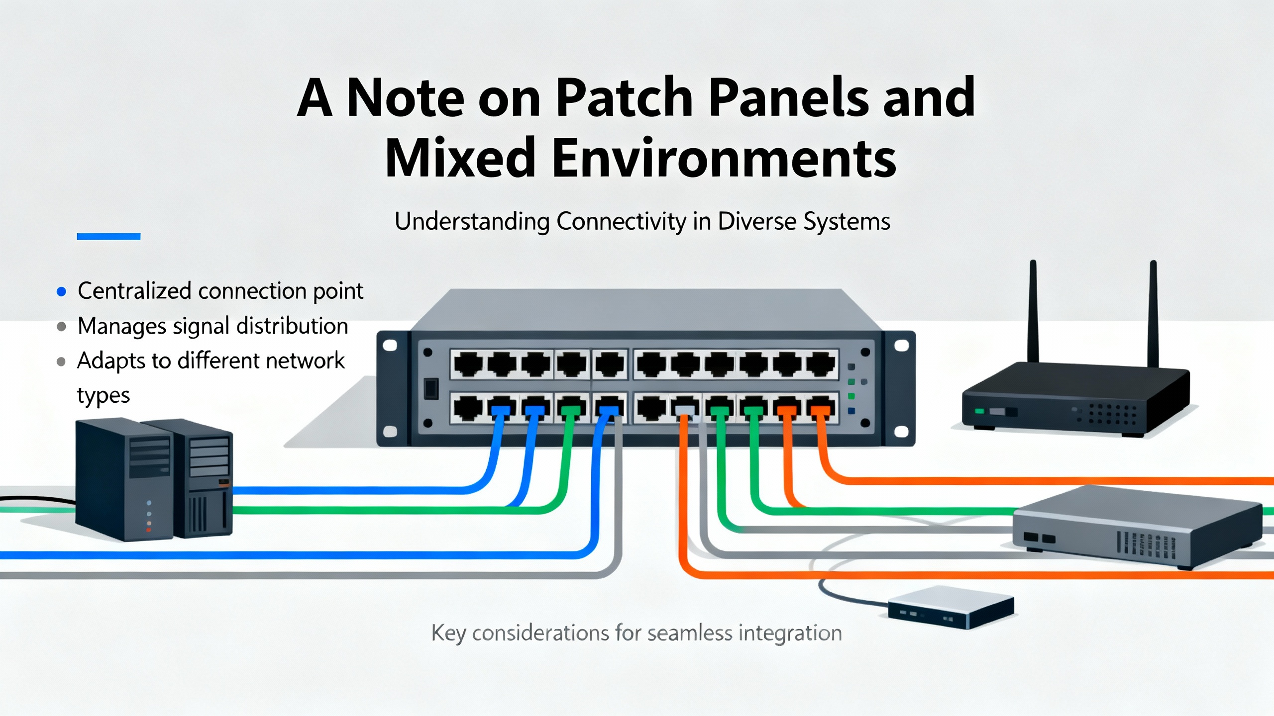
A Note on Patch Panels and Mixed Environments
Many modern systems blend industrial control with networked devices in the same cabinet. When patch panels for twisted‑pair Ethernet or fiber appear in a control panel, treat those pathways with the same routing discipline described above. Keep patch leads short and correctly rated, use lacing bars and horizontal managers to route between the patch panel and switch, and label both ends per ANSI/TIA‑606 so the network map is obvious. The maximum Ethernet channel length is 328 ft; this matters more for facility cabling than internal panel routing, but it serves as a useful sanity check during design. Shielded cabling has a place in high‑EMI environments near VFDs and large motors; match shielded patch panels and grounding strategies accordingly.
Quick Reference Table: Wiring Duct and Use
| Duct Type | Access Pattern | Pros | When to Use |
|---|---|---|---|
| Slotted, narrow | Frequent branch‑outs with small wires | Easy entry/exit, dense routing | Signal wiring to dense terminal blocks and PLC I/O |
| Slotted, wide | Mixed gauges and frequent rework | Better support, flexible capacity | Mixed power and control runs inside large enclosures |
| Solid wall | Infrequent access | Cleaner appearance, contained | Fixed runs with minimal change; segregated power pathways |
These characteristics and their relevance to EMC and serviceability are consistent with vendor guidance from c3controls and industrial wiring references.
Takeaway
The panels that age well are the ones built with a plan and verified with discipline. Separate noisy from sensitive circuits, route along predictable pathways, make terminations that survive heat and vibration, and label so a stranger can find the right wire in a hurry. Choose components and accessories with ratings that match your environment and leave room in your wireways for the inevitable change. Most of all, inspect, document, and re‑inspect. This is how you turn standards into uptime.
FAQ
What standards should I keep at hand when designing and wiring a control panel? For industrial control panels at 600 V and below, NFPA 79 and NEC Article 409 are the primary references in the United States. IEC 60204‑1 provides complementary guidance used globally. For labeling and administration, ANSI/TIA‑606 offers a consistent framework. Product selection for wiring duct ties back to UL 1565, CSA C22.2, and IEC 61084‑2‑1. These sources inform routing, bend space, identification, and safety.
Is it worth paying for shielded cable inside the panel? Shielding pays off where you have high‑di/dt power circuits near sensitive analog or high‑speed signal runs, and near VFDs or switching supplies. In quiet neighborhoods of the panel, standard‑quality cable routed with proper separation and grounding typically performs well. This position aligns with industrial EMC guidance; choice should still be validated against the device manufacturer’s recommendations.
Should I use zip ties or hook‑and‑loop straps in wireways? Use hook‑and‑loop for most bundling inside panels because it avoids over‑compression, preserves bend radius, and makes changes painless. Reserve zip ties for permanent strain relief or lockouts where you want a one‑time clamp. This approach is supported by field experience across broadcast racks, IT cabinets, and industrial enclosures.
How much slack should I leave at devices and in ducts? Leave a small service loop at terminations so devices can be replaced without tension on conductors, and coil modest extra length under nearby wireway covers. There is no one measurement in the codes; design the loop to be accessible and protected. For bend radius, follow manufacturer data. When absent, a conservative rule adapted from high‑speed cabling is to keep bends roughly ten times the cable diameter; this is an inference rather than a panel‑specific prescription.
How do I set up a maintenance routine for wiring? Before energizing, pull‑test and torque‑verify terminations and confirm labeling. After the first operational period, schedule a re‑inspection to catch settling or vibration effects, then roll into your normal maintenance calendar. Update drawings and cable maps when changes occur. This blend of upfront QC and early re‑inspection is a pragmatic practice validated in vibration‑prone applications and translates well to fixed panels.
What labeling standard is practical for a single machine panel? ANSI/TIA‑606 scales down well even for one‑off machines. Adopt a simple, consistent scheme that names devices, terminals, and cable endpoints, and print durable labels that withstand the enclosure environment. A one‑page legend inside the door ensures any technician can decode the scheme without guesswork.
Sources Acknowledged
This guidance reflects experience on commissioning teams and aligns with reputable sources including NFPA 79 and NEC Article 409 for panel safety, IEC 60204‑1 for machinery wiring, ANSI/TIA‑606 for labeling, c3controls on wiring duct and terminal block selection, Electrical Engineering Portal for internal routing and EMC practices, Brady and Essentra for materials and accessories, and community insights from seasoned practitioners who emphasize serviceable bundling and precise labeling over cosmetic tricks. Where I inferred practices from adjacent domains, such as spare pathway capacity and conservative bend radius, I have called that out with moderate confidence.
References
- http://gamma.cs.unc.edu/CABLE_PLAN/paper.pdf
- https://upcommons.upc.edu/bitstream/handle/2117/420818/Article%20-%20CarlesBertranPujol.pdf?sequence=3
- https://do-server1.sfs.uwm.edu/file/607520WY09/ppt/48384WY/network__design__basics__for__cabling-professionals.pdf
- https://frcdocs.wpi.edu/en/2020/docs/hardware/hardware-basics/wiring-best-practices.html
- https://electrical-engineering-portal.com/tips-wiring-industrial-control-panel
- https://www.bradyid.com/resources/network-cable-management-guide
- https://www.c3controls.com/white-paper/wire-cable-management?srsltid=AfmBOorfFFyhfTJvNVo86QtqAEn4sQ1fvJBgJh5X82ZEFTEkItt-8yOA
- https://www.humanscale.com/insights/cable-management-guide-a-comprehensive-approach-to-organizing-cables-?srsltid=AfmBOoqsegVZDME_gKMtRcQj0Z0jgvM2EU_1JtzUmD_789SJgylYNN6a
- https://passive-components.eu/best-practices-for-cable-management-in-high-speed-and-high-density-systems/
- https://simcona.com/blog/control-panel-wiring
Keep your system in play!
Top Media Coverage
Categories


Related articles Browse All
-
 amikong NewsSchneider Electric HMIGTO5310: A Powerful Touchscreen Panel for Industrial Automation2025-08-11 16:24:25Overview of the Schneider Electric HMIGTO5310 The Schneider Electric HMIGTO5310 is a high-performance Magelis GTO touchscreen panel designed for industrial automation and infrastructure applications. With a 10.4" TFT LCD display and 640 x 480 VGA resolution, this HMI delivers crisp, clear visu...
 -
 BlogImplementing Vision Systems for Industrial Robots: Enhancing Precision and Automation2025-08-12 11:26:54Industrial robots gain powerful new abilities through vision systems. These systems give robots the sense of sight, so they can understand and react to what is around them. So, robots can perform complex tasks with greater accuracy and flexibility. Automation in manufacturing reaches a new level of ...
 -
 BlogOptimizing PM Schedules Data-Driven Approaches to Preventative Maintenance2025-08-21 18:08:33Moving away from fixed maintenance schedules is a significant operational shift. Companies now use data to guide their maintenance efforts. This change leads to greater efficiency and equipment reliability. The goal is to perform the right task at the right time, based on real information, not just ...


- Q&A
- Policies How to order Part status information Shipping Method Return Policy Warranty Policy Payment Terms
- Asset Recovery
- We Buy Your Equipment. Industry Cases Amikong News Technical Resources Why choose us
- Registered Address
-
32D Guomao Building, No.388, Hubin south Road, Siming district, Xiamen,Fujian, China

Leave Your Comment