
-
Please try to be as accurate as possible with your search.
-
We can quote you on 1000s of specialist parts, even if they are not listed on our website.
-
We can't find any results for “”.
Complete Guide to PLC Module Failure Diagnosis and Solutions
As a systems integrator who has spent long nights bringing stubborn lines back to life, I’ll be direct: most PLC “failures” aren’t the CPU. They are module-level problems around power, I/O, communications, grounding, or environment. This guide focuses on diagnosing those PLC module issues with a practical workflow you can use today, while noting where reputable sources converge and where they differ. You will find definitions, field-proven methods, concise comparison tables, care and buying advice, and clear guidance for intermittent faults that trigger nuisance shutdowns.
Safety First and Scope
Treat every diagnostic step as a safety task. Apply lockout/tagout per 29 CFR 1910.147 before moving hands or probes into energized enclosures, and control stored energy on actuators that may move unexpectedly. The scope here is the modular layers around the PLC CPU: power supplies, discrete and analog I/O modules, network/communication cards, and the memory layer that safeguards your program.

What Counts as a PLC Module Failure
A PLC module failure is any condition where a pluggable module in the control system no longer performs its intended function within spec, even if it appears “alive.” This includes power supplies that sag under load, input modules that miss transitions, output modules that drive weakly or leak, communication cards that drop packets, and memory subsystems that lose configuration or corrupt data. Multiple sources emphasize that the CPU is statistically the least likely point of failure; PLC Training makes this explicit and recommends re-downloading logic from a known-good file before replacing a processor. AES and MRI Automation, however, document real CPU-side symptoms such as overheating, unresponsive states, or memory corruption. Both can be true depending on context: most day‑to‑day outages originate at the edges or in the environment, yet CPU-level symptoms do occur, especially in harsh panels and poorly maintained systems.
A Proven Diagnostic Workflow
Start with power integrity, then communications, then I/O modules, and finally program integrity. MRI Automation stresses beginning with the basics: verify input voltage and stability with a meter and check upstream protection, power conditioning, and grounding. For networked systems, PLC Training notes that the vast majority of communication outages trace to physical causes at the plant floor—cables, connectors, power, or driver state. Their rule of thumb is about nine out of ten faults are physical; treat this as a practical heuristic rather than a guarantee, and validate by performing a physical-layer audit before deep protocol analysis.
Next, narrow the problem by dividing the machine into smaller sections and, when possible, exercising the process in manual mode. Trace the logic from a failed real-world action back through outputs, interlocks, and inputs to find the missing condition. For intermittent issues, add a simple “trap” rung that latches a diagnostic bit when suspected conditions align; PLC Training recommends this as a way to capture the momentary truth that disappears before you arrive with a laptop. Use the PLC’s diagnostic flags, module LEDs, and event logs; MRI Automation also recommends “simulate or jumper” techniques to confirm input-channel behavior and a meter or test light for outputs.
Module-by-Module Diagnosis Matrix
Use the following matrix to speed triage. It consolidates recommendations echoed across MRI Automation, AES, PLC Training, and PLC Technician.
| Module | Common symptoms | Quick isolates/tests | Likely root causes | Fast fix | Durable remedy |
|---|---|---|---|---|---|
| Power supply | Random reboots, brownouts, intermittent I/O chatter, nuisance trips under load | Measure DC bus under nominal and peak load; watch ripple; thermal scan; inspect terminals | Upstream sags, loose terminations, overloaded 24 VDC, heat-soaked supply | Tighten, clean, reseat; offload a high‑inrush device; cool the panel | Right-size supply with headroom; add surge protection; improve ventilation; separate dirty loads; periodic torque checks |
| Discrete input module | Inputs miss quick transitions; false ON from noise; diagnostic LED disagrees with field state | Jumper test at module; debounce timer check; scope or software monitor on channel; review commons | EMI/RFI coupling, poor shielding/grounding, shared commons, wet connectors | Replace suspect sensor; reroute away from drives; add simple RC filter | Shielded cable to bonded ground; input filtering; isolation relays; fix ground integrity per AES |
| Discrete/analog output module | Output won’t energize or is weak; analog drifts; fuses blow | Meter or test light at terminal; swap with known-good channel; inspect field load | Overcurrent, load short, relay wear, thermal stress | Replace fuse or module; isolate shorted load | Add external relays; derate current; improve heat sinking; document load specs |
| Communication card (Ethernet/serial/fieldbus) | Drops to HMI/SCADA; I/O adapters time out; blinking link LEDs | Swap cable; ping test; check port LEDs; verify IP/baud; try a known-good switch port | Damaged cables, misconfigured settings, bad drivers after updates, noisy power | Reseat connectors; set correct parameters; reinstall driver; move cable | Replace cable plant; avoid default IP/node; add managed switching and isolation; segment noisy devices; maintain firmware alignment |
| CPU/memory storage | Unexpected faults at boot; programs revert; odd arithmetic errors | Compare online logic to master; check fault codes; battery status; CPU temp | Memory battery failure, file corruption, thermal issues, power events | Reload known-good program; allow cooldown; reseat | Add EEPROM/flash auto‑load on memory error (PLC Training); version control; panel cooling; UPS or ride‑through |
Two nuanced points deserve emphasis. First, PLC Technician warns that handheld radios and antennas close to a panel can inject RFI that looks like ghost inputs; keeping transmitters out of the cabinet zone and improving shielding can resolve seemingly “unsolvable” intermittents. Second, PLC Training mentions a diagnostic clue on some platforms where a value around 37,767 appears in a register when a math overflow occurs. Because vendors differ, treat this as a vendor‑specific sentinel rather than a universal truth and confirm by replicating the calculation in a safe test project while watching the platform’s official overflow flag.
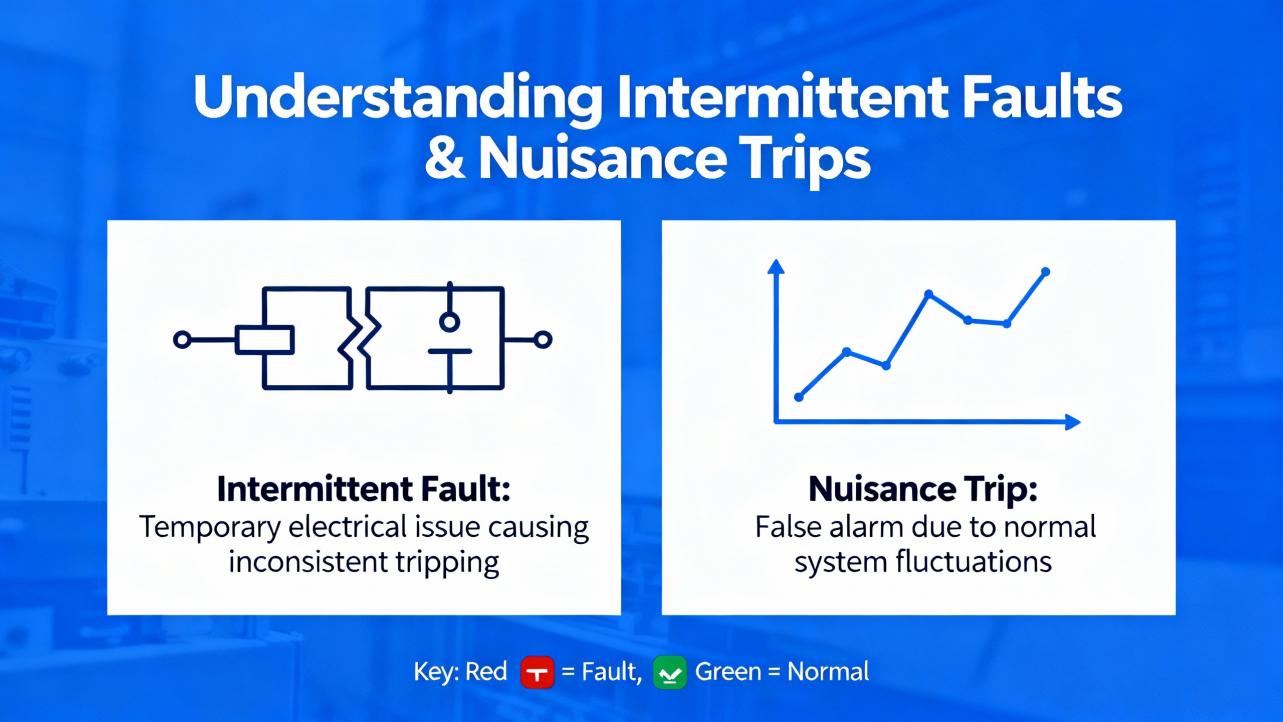
Intermittent Faults and Nuisance Trips
Intermittent input dropouts are the bane of production lines because they are short-lived and hard to reproduce. The Mike Holt forum query highlights exactly this scenario: inputs dropping for a split second and triggering shutdowns even after swapping sensors and input cards. In practice, you will need both event capture and elimination-by-evidence.
Begin by adding a trap rung to latch a diagnostic bit when the machine is running and the suspect input drops while related permissives are true. Couple this with a time-stamped counter in the PLC so you can correlate the event with production state. If your platform supports high-speed task diagnostics, subscribe the input into a faster task or use a built-in data logger. MRI Automation suggests using a quick jumper or simulator to exercise the input channel; that proves the module channel can see transitions. If the channel behaves with a simulator but not with the sensor, move upstream to the sensor wiring harness and connector.
Two subtle failure patterns are often missed. One is a ground integrity problem that creates a small voltage offset, raising the noise floor and making a threshold input “flap”; AES recommends verifying single-point grounding and eliminating unintended returns. The other is thermal cycling in outdoor or poorly ventilated panels; MRI Automation notes heat and humidity as recurring culprits. In hot climates it is common to see panels creep past 95°F and then cool quickly overnight, leading to condensation and intermittent connections during the morning shift. If that hypothesis fits your site history, validate with a simple temperature and humidity logger inside the cabinet over a few days, then decide on panel cooling and a small enclosure heater.
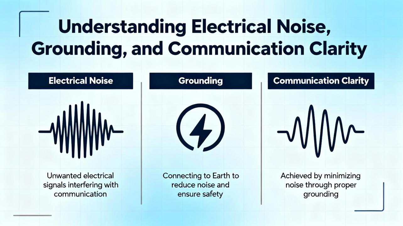
Electrical Noise, Grounding, and Communication Clarity
Noise masquerades as logic problems. EMI from big motors and nearby lightning, and RFI from handheld transmitters, turn clean edges into fuzz. AES advises addressing ground loops by verifying ground integrity, isolating sensitive devices, and applying shielding. Keep high‑voltage conductors separate from low‑level sensor lines and bond shields at a single, intentional point to avoid forming an antenna. For networks, PLC Training’s physical-first workflow saves time: inspect connectors, confirm power and drivers, and only then analyze protocols. MRI Automation recommends checking port LEDs and pinging devices to determine whether the failure is physical or logical in minutes.
When sources disagree on which category is “most common,” context explains it. Shop‑floor training content tends to emphasize physical wiring and networking issues because they dominate in day-to-day troubleshooting. Service providers that see escalated cases document more CPU and program corruption symptoms. Both perspectives help: work the physical layers first because they are quick to rule in or out, and then elevate to logic integrity.
Program Integrity and Memory Protection
Program corruption is a real failure mode. AES and MRI Automation both flag corrupted memory, bad or weak batteries, and misaligned or outdated firmware as root causes of erratic behavior. Always compare the online logic with your master copy and redeploy a known‑good file when in doubt. PLC Training recommends configuring EEPROM or flash to auto‑load on memory error so the controller can fall back to a clean image. Maintain version control, including date‑stamped builds, and store master images off the machine network. If you see arithmetic anomalies, check overflow and divide-by-zero flags and audit recent code changes around scaling, averaging, and PID operations.
Environmental Stress Is a Root Cause, Not a Side Note
MRI Automation calls out heat, humidity, dust, insects, and blocked ventilation as quiet killers. AES adds corrosion and poor grounding. A hot, dirty panel reduces power-supply output capability, pushes module components toward early wear, and destabilizes analog measurements and network PHYs. If your site regularly exceeds comfortable room temperature, plan for climate-controlled panels, breathable but filtered enclosures, and regular cleaning. Where outdoor duty is unavoidable, specify sealed enclosures with appropriate gasketing, sunshades, and a small anti‑condensation heater.
Care and Maintenance That Prevent Module Failures
Reliability is proactive. Make backups of PLC programs as soon as you go online, storing a copy named with context like “current” or “faulted” as PLC Training suggests, so you can revert after experimental changes. Schedule periodic inspections to re‑torque terminals, verify I/O wiring strain relief, check module diagnostic LEDs, and confirm fan operation. For communications, avoid default IP addresses and add devices one at a time while verifying connectivity, as PLC Training recommends. For I/O, document channel mapping and commons to avoid hidden shared‑return problems that emerge only at peak load. For power, measure voltage under load and log it during major production cycles.
Selecting the Right Replacement or Spare Modules
Choosing modules is not just about part numbers; it is about fitness for your environment and maintenance model. The table below distills selection criteria into actionably specific terms you can check against datasheets and your plant’s conditions.
| Criterion | Why it matters | What good looks like |
|---|---|---|
| Operating temperature rating | Hot panels derate electronics and increase failures | A rating that exceeds your enclosure’s worst‑case by comfortable margin, with consideration for solar load; plan for below‑freezing starts if applicable |
| Isolation and diagnostics | Prevents cross‑talk and speeds future troubleshooting | Channels with clear status LEDs, per‑channel diagnostics, and robust isolation stated in volts; analog cards with open‑wire and over‑range detection |
| Channel density vs. maintainability | High density saves space but can increase blast radius | A balance that keeps critical functions separated; removable terminals for fast swap |
| Firmware/tooling alignment | Avoids subtle incompatibilities | Module firmware approved for your controller revision; software version pinned and archived with the master program |
| EMC immunity | Resilience to EMI/RFI | Compliance with relevant immunity standards; shield termination guidance in the manual; proven performance in your drive‑heavy zones |
| Field wiring ecosystem | Serviceability under time pressure | Pluggable terminals, clear labeling, spare fuses on board or easy external holders, space for ferrules and boots |
| Lifecycle and sourcing | Availability during failures | Confirm active lifecycle with the OEM or a reliable distributor; maintain a sparing plan for long‑lead modules |
If you are considering refurbished modules, weigh cost savings against the need for burn‑in and warranty support. In critical cells, the risk calculus often favors new modules with traceable provenance.
Overlooked Insights You Can Put to Work
Several practical ideas recur less often in public guides but make a difference on the floor. First, when intermittent input faults defy explanation, check the cabinet’s radio environment; PLC Technician notes that handheld transmitters can induce RFI close enough to mimic a flaky sensor. Second, many “communication crashes” are actually power dips to switches or adapters; PLC Training’s physical‑layer emphasis fits this pattern, so put your meter on the switch power supply and wiggle the cable while watching voltage and link LEDs. Third, arithmetic anomalies that only appear on hot days frequently trace to scaling around analog modules whose reference drifts; this is an inference based on experience rather than a formal statistic, and the fastest way to validate is to log raw counts and scaled engineering units over a warm afternoon and compare drift against module spec.

Putting It All Together in the Field
When faced with a line stoppage tied to a suspected module, stabilize power and environment first, then prove or disprove a module fault with a quick substitution or simulator while logging the state the moment the fault occurs. Only after the physical and environmental layers are cleared should you commit to rewriting control logic or replacing the CPU. MRI Automation’s recommendation to review logs, compare logic to a master, and re‑upload a known‑good program is a safe and efficient final step.

Takeaway
Module failures look like software until you measure. Start with power quality and ground integrity, then prove the network’s physical health, then isolate I/O behavior at the terminals, and only then touch logic. Keep disciplined backups, use trap rungs to catch intermittents, and invest in panel climate and shielding. The CPU is rarely the root, but program integrity and memory protection still need a plan. This discipline shortens downtime and lowers spare parts spend without gambling on blind swaps.
FAQ
Q: How do I tell if an input module or a sensor is at fault during intermittent dropouts? A: Use a simulator or jumper at the input terminal to exercise the channel while the process is otherwise unchanged. If the module registers consistently with the simulator but not with the sensor, work upstream through the cable, shield termination, and sensor power. This approach aligns with MRI Automation’s quick checks and saves time.
Q: Are most network communication faults configuration mistakes or hardware issues? A: In many plants, hardware and physical plant conditions dominate. PLC Training suggests a practical rule that most established network failures trace to physical attributes like cables, connections, power, or drivers. Treat that as a starting hypothesis and validate by inspecting and swapping physical components before deep protocol work.
Q: My PLC reboots sporadically after hot runs. Is the CPU failing? A: Possibly, but more often the power supply sags, panel heat rises, or both. Verify the 24 VDC line under load, check panel temperature, and inspect the CPU’s diagnostic logs. If you still suspect the CPU, reload a known‑good program and ensure memory protection is configured. AES and MRI Automation both note environmental factors as frequent root causes.
Q: Can a programming error really look like a module failure? A: Yes. Overflow, divide‑by‑zero, or mis‑scaled analog routines can produce symptoms identical to bad hardware. On some platforms a value around 37,767 indicates overflow, per PLC Training, but always confirm using your vendor’s documented flags. Compare the current logic to the master and re‑test with known inputs before ordering parts.
Q: What are the best spares to keep on hand? A: Prioritize a right‑sized 24 VDC power supply, the most common discrete input and output cards in your facility, one communication module per network type in use, and spare terminal blocks and fuses. Ensure firmware compatibility with your installed base and archive the matching software tools alongside your master programs.
Q: How do I prevent ground loop issues that cause erratic readings? A: Establish a single‑point ground strategy, bond shields intentionally, separate high‑voltage and low‑level wiring, and consider isolation for sensitive channels. AES emphasizes verifying ground integrity and eliminating unintended ground paths; a quick audit with a meter and visual inspection often uncovers the culprit.
By combining a disciplined physical-first workflow with targeted module tests, environmental controls, and strong program management, you will diagnose PLC module failures faster and avoid repeat outages. Sources including MRI Automation, AES, PLC Training, PLC Technician, and practitioners on the Mike Holt forum converge on this pragmatic approach, and it has held up reliably across diverse industries from packaging to water treatment.
References
- https://www.academia.edu/59553480/Systematic_Anticipation_and_Validation_of_Scenarios_of_Failure_Propagation_and_Mitigation_in_PLC_Controlled_Processes?f_ri=1993475
- https://www.cs.ucdavis.edu/~peisert/research/2019-IJCIP-DetectingPLCCode.pdf
- http://websites.umich.edu/~tilbury/logiccontrol/lcms-report.pdf
- http://oaktrust.library.tamu.edu/bitstream/1969.1/ETD-TAMU-2010-08-8453/3/SEKAR-THESIS.pdf
- https://digital.library.unt.edu/ark:/67531/metadc871611/m2/1/high_res_d/1114573.pdf
- https://plc-training.org/plc-troubleshooting-bp4.html
- https://electrical-engineering-portal.com/plc-troubleshooting
- https://gesrepair.com/diagnosing-and-repairing-plc-module-failures
- https://www.aesintl.com/plc-faults-and-troubleshooting-procedures/
- https://www.gicindia.com/plc-troubleshooting-tips-common-issues-and-how-to-resolve-them/
Keep your system in play!
Top Media Coverage
Categories


Related articles Browse All
-
 amikong NewsSchneider Electric HMIGTO5310: A Powerful Touchscreen Panel for Industrial Automation2025-08-11 16:24:25Overview of the Schneider Electric HMIGTO5310 The Schneider Electric HMIGTO5310 is a high-performance Magelis GTO touchscreen panel designed for industrial automation and infrastructure applications. With a 10.4" TFT LCD display and 640 x 480 VGA resolution, this HMI delivers crisp, clear visu...
 -
 BlogImplementing Vision Systems for Industrial Robots: Enhancing Precision and Automation2025-08-12 11:26:54Industrial robots gain powerful new abilities through vision systems. These systems give robots the sense of sight, so they can understand and react to what is around them. So, robots can perform complex tasks with greater accuracy and flexibility. Automation in manufacturing reaches a new level of ...
 -
 BlogOptimizing PM Schedules Data-Driven Approaches to Preventative Maintenance2025-08-21 18:08:33Moving away from fixed maintenance schedules is a significant operational shift. Companies now use data to guide their maintenance efforts. This change leads to greater efficiency and equipment reliability. The goal is to perform the right task at the right time, based on real information, not just ...


- Q&A
- Policies How to order Part status information Shipping Method Return Policy Warranty Policy Payment Terms
- Asset Recovery
- We Buy Your Equipment. Industry Cases Amikong News Technical Resources Why choose us
- Registered Address
-
32D Guomao Building, No.388, Hubin south Road, Siming district, Xiamen,Fujian, China

Leave Your Comment