
-
Please try to be as accurate as possible with your search.
-
We can quote you on 1000s of specialist parts, even if they are not listed on our website.
-
We can't find any results for “”.
Control Valve Actuator Failure: Inspection and Repair Guide
Control valves are the last thing between a stable process and a bad night shift. In most plants I have worked with, when a loop goes unstable or a unit trips, the actuator on a critical control valve is very often where the problem shows up first. The actuator is the muscle of the valve assembly; when it fails, you see leaks, sticking, noisy operation, or a valve that simply refuses to move.
This guide walks through how actuator failures present in the field, what typically causes them, and how to inspect and repair them in a way that is systematic, safe, and repeatable. The guidance is grounded in field practice and supported by industry references such as Allied Valve Inc., ISA’s Control Valves handbook, and troubleshooting articles from Control.com, JHFoster, Tameson, and others.
My goal is to give you the same structured approach my teams use when we are called in as the “last resort” on a stubborn valve problem.
What A Control Valve Actuator Actually Does
A control valve sits in the line and modulates flow, pressure, or level. The actuator on top converts an energy source into motion to position the valve plug, ball, or disc. In modern process control, the actuator is commanded by a controller through a positioner, often with a standard 4–20 mA signal that the positioner converts to air pressure or motor movement.
Pneumatic actuators are still the workhorse in most process plants. A current signal from the PLC or DCS drives an I/P (current to pressure) converter, which in turn feeds the actuator. A typical setup uses instrument air where minimum pressure drives the valve toward closed and higher pressure, often in the range of about 15 psi at the diaphragm or piston, drives it toward open. Springs establish a fail-safe position on loss of air.
Electric or motor-operated valve actuators use an electric motor with gear reduction, limit switches, and torque switches. They are common where instrument air is not available or where tight electronic integration is needed.
Gas-over-hydraulic or gas-over-oil actuators use process or fuel gas to pressurize hydraulic fluid, which then moves a piston. These show up on safety-critical and pipeline valves where very high torque and defined fail positions are required.
The important point is that when the actuator misbehaves, the process only sees the symptom: the valve leaks, sticks, or fails to respond. The trick is separating what is truly a valve-body issue from what is rooted in actuator failure, sizing, or calibration.
How Actuator Failure Shows Up In The Process
Internal And External Leakage
Several sources, including Allied Valve Inc. and Control.com, make an important distinction between internal and external leakage.
Internal leakage means unwanted flow through the valve when it is supposed to be shut. ANSI/FCI Standard 70-2 recognizes that control valves are not usually designed for perfect shutoff; it defines leak rate classes and a maximum allowable leakage for each class. A small amount of internal leak can be acceptable if it is within the specified class. When leakage exceeds that maximum allowable level, particularly after the valve has been in service for some time, you are looking at an issue with internal trim wear, misalignment, or actuator and positioner calibration.
External leakage is fluid or gas escaping to atmosphere around packing, body joints, or actuator interfaces. Articles from Allied Valve and JHFoster point out that control valves are among the worst offenders for fugitive emissions in refining and chemical service, usually due to packing problems. Improper packing maintenance, temperatures beyond packing design, vibration, thermal cycling, and material incompatibility all degrade packing over time. When operators respond to a leak by cranking down the packing gland, they often trade an external leak for a sticky valve.
In practice, I start by asking whether the leak is internal, external, or both. Internal leakage drives product loss and control problems; external leakage drives safety and environmental risk. The inspection approaches are different, and the actuator’s role is different in each case.
Sticking, Crawling, And Valves That Will Not Move
Stiction, or “stick plus friction,” is one of the most common symptoms of actuator or packing trouble. Research from ITC Engco and JHFoster describes how valves with stiction sit motionless until enough force builds up, then suddenly jump past their intended position. In the control room, you see a saw-tooth pattern in the controller output and a jerky process variable.
Crawling is a symptom JHFoster associates especially with pneumatic pilot-operated valves. The valve moves very slowly or only partway, often because pilot pressure is low, pilot passages are dirty, or internal components are too tight. With undersized or tired actuators, crawling shows up whenever the required thrust or torque is close to the actuator’s mechanical limit.
A valve that does not move at all can be due to a stuck valve body, a dead actuator, or a missing command signal. The Allied Valve article on actuator failures lists common issues such as incorrect motive pressure, incorrect solenoid voltage, plugged solenoid ports, and broken diaphragm or springs for pneumatics, as well as blown fuses, power board failures, or mis-set limit switches on electric actuators. Without a structured inspection, it is easy to waste hours on the wrong component.
Noise, Vibration, And Unstable Control
Noise and vibration are not just annoyances; they are diagnostics. Articles from HydraulicValves.tech and Pioneer Industrial point out that hissing, whistling, or cavitation-like hammering often indicate high velocities, cavitation, flashing, or incorrect valve sizing. If the actuator cannot position the valve steadily because of dead band, overshoot, or stiction, you will also see cycling and vibration propagated into the piping.
In many of the control loops I review, what the operator calls “valve noise” is actually the valve being oversized and operating in a very small stroke band. A tiny position change produces a large flow change, the controller overreacts, and the actuator spends its life chasing the setpoint. That accelerates wear and sets you up for early failure of both valve and actuator.
Root Causes Of Control Valve Actuator Failure
Pneumatic Rotary And Cylinder Actuators
For pneumatic rotary and cylinder actuators, Allied Valve’s “40 reasons your actuator is not working” and Tameson’s troubleshooting guide highlight a set of recurring themes.
Air issues are at the top of the list. Incorrect motive pressure, blocked or clogged filters, plugged actuator ports, closed speed controls, and system leakage upstream of the actuator all reduce the available air volume and pressure. If you do not maintain air quality, moisture and oil carryover will condense in the actuator and positioner, leading to corrosion, sticking spools, and seal damage. JHFoster emphasizes that dryers and filters need regular servicing so that moisture is actually removed and drained, not just trapped.
Mechanical wear and sizing errors are just as significant. Broken springs in spring-return units, worn or hardened seals, undersized actuators asked to deliver more torque than they were designed for, and excessive side loading on piston rods all show up as sluggish or incomplete movement. When valve internals have become tight due to corrosion or debris, increased thrust demand can make an actuator that was marginally sized when new look “weak” even though the real problem is downstream.
In the field, if I see a pneumatic actuator struggling at the end of stroke, I look for three things in order: air supply quality and pressure, increased mechanical friction in the valve, and actuator sizing versus current process conditions.
Electric (Motor-Operated) Actuators
Electric or motor-operated valve actuators fail in two broad ways: electrical and mechanical.
On the electrical side, the Allied Valve guidance notes incorrect supply voltage, incorrect control voltage to the actuation circuit, blown fuses, and power board failures as common culprits. Miswired or loose conductors, tripped thermal overloads, and incorrect power phasing on three-phase units are also frequent causes. A surprising number of “dead actuators” turn out to be mis-set or failed limit switches that tell the motor control that the valve is at end of travel when it is not. Quick-disconnect harnesses loosened by vibration are another recurring issue.
On the mechanical side, you see binding in the valve stem, damaged or worn drive nuts, stripped center column gears, or stripped worm gears and motor pinions. Torque switches can trip when the valve encounters excessive resistance, then remain latched until reset. If the handwheel declutch mechanism fails, the actuator may be effectively disengaged from the valve even though the motor is spinning.
Eagle Fittings and other actuator suppliers also point out secondary symptoms such as overheating, burning smells, grinding or clicking noises, and erratic movement or drifting position. These usually trace back to motors working against stuck valves, worn gears, or calibration issues in position feedback devices.
Gas-Over-Hydraulic And Gas-Over-Oil Actuators
Gas-over-hydraulic actuators are common on safety-critical pipeline valves and emergency shutdown valves. Allied Valve’s troubleshooting examples show that many field problems here are basic configuration or commissioning mistakes.
If the valve and actuator are not in the same orientation, the actuator may hit its travel limits while the valve is still partially open or closed. Missing keys in the mechanical drive train, shipping plugs left in gas supply or exhaust ports, or blocked tubing between gas supply and hydraulic tanks can leave the actuator unable to stroke even though control signals look fine.
Low power-gas pressure, closed speed controls, low hydraulic fluid levels, failed hand pumps, and worn actuator seals all reduce available force or speed. Because these actuators often protect high-risk services, seal failures or fluid leaks must be treated as reliability issues, not just housekeeping problems.
Cross-Cutting Issues: Sizing, Calibration, And Misapplication
Several sources, including Allied Valve, HydraulicValves.tech, ITC Engco, and Pioneer Industrial, converge on three systemic root causes: wrong sizing, poor calibration, and misapplied service conditions.
If an actuator is undersized, it cannot deliver the thrust or torque needed when process conditions worsen, media becomes more viscous, or internal corrosion increases friction. If it is oversized, you can introduce dead band and poor controllability, which in turn lead to cycling and mechanical wear.
Positioner and actuator calibration problems are just as serious. Control.com and Tameson describe how an I/P or positioner that does not map 4–20 mA correctly to valve travel leads to valves that are effectively half-open when the controller thinks they are at a different position. This shows up as off-spec flow, loop oscillation, and trim damage. Dead band and overshoot from poorly tuned positioners add to the problem.
Finally, misapplication is often the invisible culprit. JHFoster and HydraulicValves.tech both note that using a valve and actuator in temperature, pressure, or media conditions beyond their design ratings dramatically shortens life. Allied Valve technicians regularly see diaphragm actuators and internal components destroyed because the assembly was never sized or specified for the actual service. Without accurate data on flow, media, and temperature during the sizing and selection process, you are essentially buying a maintenance problem.
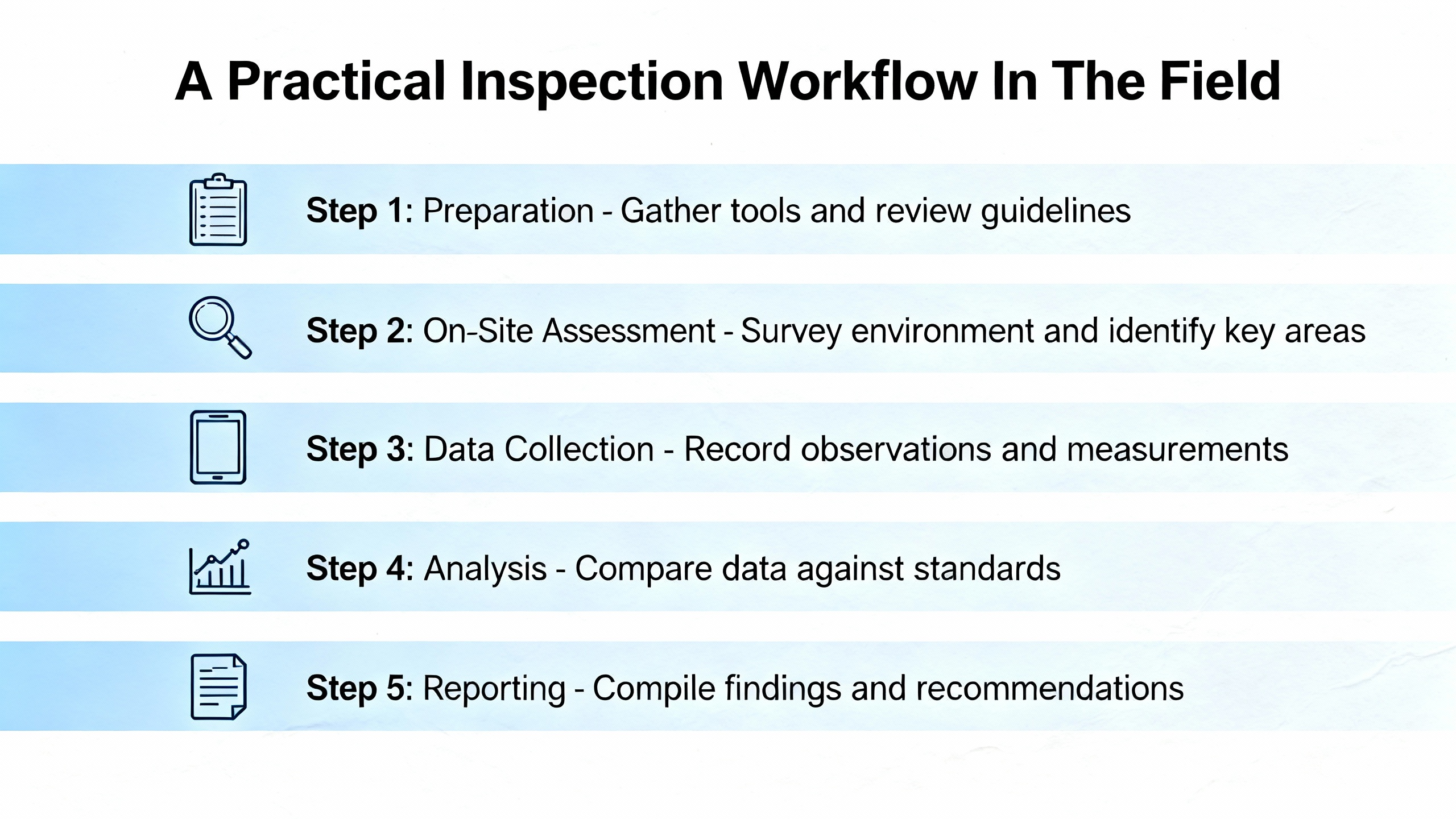
A Practical Inspection Workflow In The Field
The most effective way to diagnose actuator-related valve problems is to follow a repeatable workflow. Experienced technicians develop this instinctively; I will lay it out explicitly so you can standardize it across your team.
Start With Safety And Isolation
Before touching a control valve assembly, confirm that the process is safely isolated. The well control troubleshooting guidance from field practitioners is clear on this point: bypass the valve where a bypass exists, reduce or eliminate pressure on the line, and follow your facility’s lockout or tagout procedures. For safety-critical valves such as emergency shutdown and process shutdown valves, coordinate with operations and safety so that taking the valve out of service does not compromise the plant.
Once isolated, verify that there is no residual energy that can move the valve unexpectedly: depressurize actuator chambers, bleed accumulators, and confirm that electrical supplies are locked out where required.
Verify Signals, Power, And Air Supply
Next, verify that the actuator is actually being told to move and has the energy to do so. Control.com’s explanation of the 4–20 mA loop and multiple actuator articles underline the importance of this basic step.
For pneumatic actuators, check instrument air pressure and quality at the actuator inlet and positioner. Compare actual pressure to the valve’s nameplate requirements and to any design documentation. Look for signs of moisture, oil, or rust in the air lines, and check filters and dryers for maintenance status. Closed speed controls or partially plugged ports are easy to overlook.
For electric actuators, confirm that supply voltage matches the actuator nameplate using a meter, and check control voltage at the terminal strip. Inspect fuses, overloads, and visible wiring for damage or loose connections. Confirm that the control system is actually sending a command, either by forcing a setpoint change or using a portable signal source.
For gas-over-hydraulic units, verify gas supply pressure, ensure that any shipping plugs have been removed from ports and tubing, and check hydraulic fluid level in the tanks.
Separate Actuator From Valve To Localize The Problem
A very effective technique, echoed by plant troubleshooting guides, is to separate the actuator from the valve stem when the design allows. Decoupling the linkage and then manually stroking the actuator with a test signal or hand pump tells you whether the actuator itself can move through its range freely.
If the actuator refuses to move when unloaded, focus on the actuator: diaphragms, pistons, seals, springs, electrical internals, or hydraulic components. If it strokes cleanly when disconnected but stalls when reattached, your problem is likely in the valve body: a bent stem, buildup on the seat, corrosion, or excessive packing friction.
When reconnecting, verify that the actuator and valve orientation and travel limits align. Misalignment here is a common reason for incomplete travel and apparent loss of thrust.
Inspect Mechanical Components And Packing
Once you know whether the actuator or valve is at fault, inspect the mechanical components. Following the guidance from JHFoster, Tameson, and C&K, go after the obvious wear points first.
Look for signs of corrosion, scoring, or galling on stems and guides. Inspect springs for cracks or breakage. Check seals, O-rings, and diaphragms for hardening, cracking, or extrusion. Examine gears and drive nuts in electric actuators for missing or rounded teeth.
Packing deserves particular attention. ISA’s Control Valves book and multiple field articles emphasize that overtightening packing to stop external leaks is a major source of stiction. Bring packing torque back within the manufacturer’s specification, replace worn or incompatible packing materials, and consider temperature and media when choosing packing types. Tighten only enough beyond hand tight to achieve proper sealing.
Check Calibration, Positioner Behavior, And Loop Tuning
Once the hardware is healthy, verify that the actuator and positioner respond correctly to control signals. HydraulicValves.tech and Tameson recommend calibrating positioners by setting zero and span against a known 4–20 mA or pneumatic signal, then confirming that valve position matches expected travel marks.
Pay attention to dead band and hysteresis: small changes in input that produce no motion or motion that reverses late. ITC Engco’s work on dead band and stiction in control loops shows how even a few percent of dead band can cause oscillation and poor control. Adjust or repair mechanical linkages and positioner settings to minimize these effects.
Do not ignore the control loop. Incorrect signal scaling, reversed controller action, and aggressive PID tuning can all make an actuator appear unstable when the real issue is in the control logic. Pioneer Industrial recommends verifying signal ranges and tuning before condemning the valve assembly.
Decide Whether To Repair, Rebuild, Or Replace
Finally, step back and look at the economics. HydraulicValves.tech notes that a typical control valve life is on the order of ten to twenty years, depending on materials, service severity, and maintenance quality. They suggest using a threshold where if the repair cost approaches about half the cost of replacement, or if the valve body is severely damaged, replacement is usually the better choice.
For actuators, Alphatronic Machinery and Eagle Fittings stress that multiple simultaneous warning signs—erratic motion, leaks, noise, and failure to hold position—often indicate broad internal wear. In those cases, rebuilding may be possible but a new actuator can be more economical and reliable, especially in sanitary or safety-critical services where certification and cleanability are key.
In my own projects, I encourage clients to standardize on a limited set of actuator and positioner models and keep spares. That reduces downtime and simplifies decisions: if a badly worn unit fails and you have a compatible spare on the shelf, replacement followed by shop repair and evaluation is often the fastest path back to production.
Common Repairs And Their Pros And Cons
Packing And External Leak Repairs
Replacing or adjusting packing is usually the quickest repair when you have external leakage at the stem. JHFoster and C&K describe the usual approach: select packing material compatible with media and temperature, remove old packing, install new rings with the correct orientation, and tighten to specified torque.
The advantage is low cost and short downtime. The downside is that if packing has been overtightened for a long time, the stem may already be scored or bent, and simply replacing packing will not restore smooth motion. Incorrect packing materials or installation techniques can also lead to repeat failures and higher fugitive emissions.
Seal, Seat, And Trim Work For Internal Leakage
When internal leakage exceeds the allowable class, you are dealing with damage or misalignment in seats, plugs, balls, or discs. Allied Valve and Pioneer Industrial recommend a combination of cleaning, flushing out debris, re-lapping of seats, or full trim replacement.
The benefit of this work is restored shutoff capability and reduced energy loss. The tradeoff is that it usually requires taking the valve out of the line and sometimes out of the unit, which can be intrusive. If erosion, corrosion, or cavitation are driving the damage, you may also need to address upstream conditions or change trim style and materials.
Actuator And Positioner Overhauls
For pneumatic actuators, overhauls typically involve replacing diaphragms, seals, bushings, and sometimes springs. For electric actuators, you may be replacing motors, circuit boards, limit and torque switches, and gear sets. Tameson and the Allied Valve actuator troubleshooting article both stress the importance of following manufacturer procedures and torque values during reassembly.
The advantage of overhaul is that it lets you keep existing wiring, piping, and mounting hardware while restoring performance. The downside is that not all actuators are worth rebuilding. Older units without available parts, or units with widespread corrosion and wear, can consume shop hours without delivering long-term reliability.
Upgrading Sizing, Materials, Or Valve Style
Some of the most persistent actuator problems are rooted in poor initial choices. ITC Engco, Pioneer Industrial, and Control.com all caution against oversized valves and actuators. A correctly sized control valve should normally operate between about twenty and eighty percent open; many well-sized valves end up one or two sizes smaller than the line.
Where you see chronic stiction, excessive cycling, or persistent leakage in aggressive services, consider upgrading valve and actuator materials or even valve style. For example, moving from a general-purpose valve to a high-performance butterfly or segment ball valve with suitable trim can reduce wear. In sanitary applications such as food and pharmaceuticals, Eagle Fittings notes that stainless steel actuators with appropriate certifications are effectively mandatory to avoid contamination and to withstand clean-in-place and steam-in-place cycles.
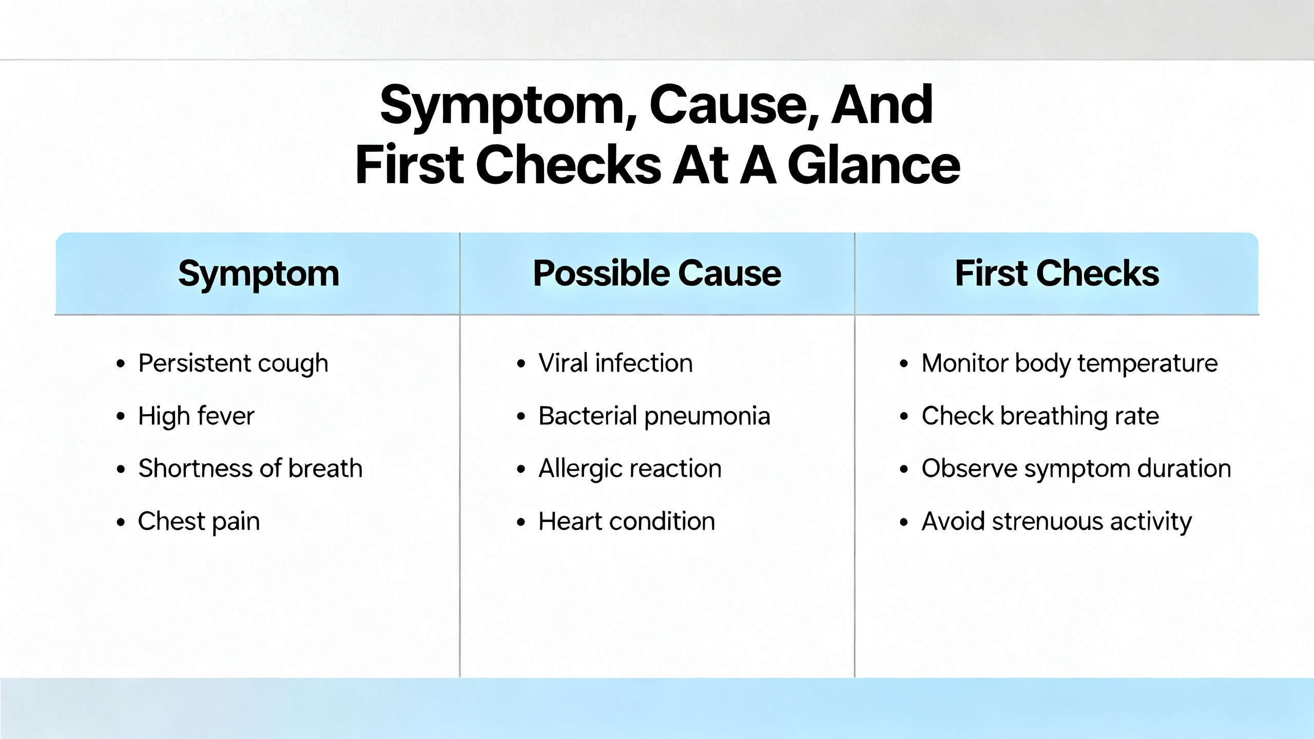
Symptom, Cause, And First Checks At A Glance
The table below consolidates key field symptoms, likely actuator-related causes, and the first checks that experienced technicians perform, based on patterns described by Allied Valve, JHFoster, Tameson, HydraulicValves.tech, and others.
| Symptom at valve or in loop | Likely actuator-related causes | First inspection and test steps |
|---|---|---|
| Valve does not move or only moves partway | No or incorrect power or air, tripped overloads or torque switches, broken springs or diaphragms, plugged ports or filters, mis-set limit switches | Verify supply voltage or air pressure, confirm control signal, check fuses and overloads, inspect air filters and solenoids, manually stroke actuator unloaded if possible |
| Valve sticks, crawls, or overshoots position | Overtightened packing, worn seals, contamination in actuator, undersized actuator, misaligned linkage, dead band or overshoot in positioner | Inspect and adjust packing, check for corrosion and debris, verify actuator sizing versus torque or thrust requirement, recalibrate positioner, observe stroke response to small signal changes |
| Internal leakage when valve should be closed | Worn or damaged seats and plugs, actuator not achieving full travel, miscalibrated positioner, increased friction requiring more force | Check travel indication versus command, perform leak test against specification, inspect trim for wear and debris, confirm actuator can reach full close position under design conditions |
| External leakage around stem or body | Packing wear, incorrect packing material, loose or damaged body gaskets, operation beyond design temperature or pressure | Visually inspect for leaks and corrosion, tighten to proper torque, replace packing with suitable material, replace gaskets and worn bolting, review operating conditions versus valve rating |
| Noisy, vibrating, or unstable control | Oversized valve or actuator, cavitation or flashing, dead band, poor air quality, incorrect loop tuning | Review valve sizing and normal operating stroke, listen for cavitation, check air dryness and pressure stability, inspect actuator linkage for play, verify controller tuning and signal scaling |
Building Reliability: Maintenance And Online Monitoring
Preventive And Predictive Maintenance Practices
All of the reputable sources in this space agree on one point: if you treat control valves and actuators as “fit and forget,” they will eventually fail at the worst possible time. HydraulicValves.tech recommends inspecting seals, gaskets, and packing every six to twelve months; cleaning valve internals during planned shutdowns; and lubricating stems and guides with process-compatible lubricants. They also advocate annual calibration checks for positioners.
JHFoster and Tameson emphasize regular leak checks on air lines and packing, verification of alignment and mounting, and protection of systems with strainers or filters to keep debris out of valves. Moisture management in compressed air systems is critical; filters and moisture collectors must be installed and actually drained.
From a system integrator perspective, I advise clients to log every actuator failure and repair, including symptoms, root cause, and corrective actions. Over a few years, this data reveals patterns: particular services that chew through actuators, recurring sizing mistakes, or specific models with reliability issues. That is the foundation for more advanced reliability programs and capital upgrade decisions.
Online Monitoring And Diagnostic Coverage For Safety-Critical Valves
For safety-critical valves such as emergency shutdown and process shutdown valves, online monitoring offers another layer of protection. Research summarized by Sotoodeh and indexed in scientific databases describes “ValveWatch” style systems that mount sensors on actuators to monitor strain and pressure during operation.
In that work, three types of sensors are highlighted: strain gauges, dynamic pressure gauges, and static pressure gauges on the actuator. By analyzing the signals from these sensors during normal strokes and tests, the system can detect emerging problems in valves, actuators, and control systems that would be difficult to see with visual inspection alone.
Using concepts from the IEC 61508 functional safety framework, the research shows how online monitoring increases diagnostic coverage, meaning the fraction of dangerous failures that can be detected. While not every facility will invest in full ValveWatch systems, the underlying principle is accessible: the more you measure and trend actuator performance, the earlier you can intervene before a failure becomes a trip or a release.

FAQ
Q: How can I quickly tell whether a problem is in the actuator or in the valve body itself?
A: After basic safety checks and verification of power or air supply, the most effective test is to decouple the actuator from the valve stem, when the design allows. If the actuator fails to stroke smoothly when unloaded, the problem is in the actuator or its controls. If the actuator strokes cleanly but stalls or struggles when reattached, the valve internals, packing, or alignment are likely at fault.
Q: Is some internal leakage always a sign that the actuator is failing?
A: Not necessarily. Control valves are designed to meet a specific shutoff class under ANSI or FCI standards, and those classes allow a defined maximum leakage. Internal leakage beyond that limit can be caused by worn seats, misalignment, contamination, or insufficient actuator force reaching the closed position. The actuator is part of the picture, but trim condition and valve sizing must also be evaluated.
Q: Should I tighten packing as much as possible to stop a stem leak?
A: No. Multiple references, including ISA and Allied Valve Inc., warn that overtightened packing is a major cause of valve sticking and premature wear. Packing should be tightened only to the manufacturer’s recommended torque and only after verifying that packing material and installation are correct. If significant torque is needed to stop a leak, replacing packing and inspecting the stem for damage is usually the better path.
In the end, a control valve actuator that fails rarely does so without warning. Leaks, noise, slow response, and unstable control are all early clues if you know how to read them. With a disciplined inspection workflow, a sound understanding of the failure modes described here, and a willingness to correct sizing and specification errors, you can turn chronic actuator trouble spots into quiet, predictable assets. That is the kind of reliability a seasoned systems integrator should deliver, and it is well within reach when you treat each problematic valve not as a nuisance, but as a chance to harden your entire control system.
References
- https://ui.adsabs.harvard.edu/abs/2020SenIm..21...57S/abstract
- https://upcommons.upc.edu/bitstreams/31d06ca1-dd53-4f0a-85ad-291ab0afccec/download
- https://www.seas.upenn.edu/~weimerj/pdf/2012-BuildSys-detection.pdf
- https://www.valen-tech.com/how-to-tell-if-an-actuator-is-bad.html
- https://wplawinc.com/what-are-signs-that-my-actuator-valve-is-not-working-correctly
- https://alphatronicmachinery.ae/blogs/5-signs-your-actuator-needs-replacement-or-servicing.php
- https://hydraulicvalves.tech/troubleshooting-common-control-valve-problems/
- https://www.pioneerindustrial.com/common-control-valve-problems-and-how-to-fix-them/
- https://tameson.com/pages/pneumatic-actuator-valve-issues
- https://www.valvemagazine.com/articles/actuator-issues-use-this-checklist
Keep your system in play!
Top Media Coverage
Categories


Related articles Browse All
-
 amikong NewsSchneider Electric HMIGTO5310: A Powerful Touchscreen Panel for Industrial Automation2025-08-11 16:24:25Overview of the Schneider Electric HMIGTO5310 The Schneider Electric HMIGTO5310 is a high-performance Magelis GTO touchscreen panel designed for industrial automation and infrastructure applications. With a 10.4" TFT LCD display and 640 x 480 VGA resolution, this HMI delivers crisp, clear visu...
 -
 BlogImplementing Vision Systems for Industrial Robots: Enhancing Precision and Automation2025-08-12 11:26:54Industrial robots gain powerful new abilities through vision systems. These systems give robots the sense of sight, so they can understand and react to what is around them. So, robots can perform complex tasks with greater accuracy and flexibility. Automation in manufacturing reaches a new level of ...
 -
 BlogOptimizing PM Schedules Data-Driven Approaches to Preventative Maintenance2025-08-21 18:08:33Moving away from fixed maintenance schedules is a significant operational shift. Companies now use data to guide their maintenance efforts. This change leads to greater efficiency and equipment reliability. The goal is to perform the right task at the right time, based on real information, not just ...


- Q&A
- Policies How to order Part status information Shipping Method Return Policy Warranty Policy Payment Terms
- Asset Recovery
- We Buy Your Equipment. Industry Cases Amikong News Technical Resources Why choose us
- ADDRESS
-
 32D UNITS,GUOMAO BUILDING,NO 388 HUBIN SOUTH ROAD,SIMING DISTRICT,XIAMEN
Leave Your Comment