
-
Please try to be as accurate as possible with your search.
-
We can quote you on 1000s of specialist parts, even if they are not listed on our website.
-
We can't find any results for “”.
DCS Controller Failover Issues: Redundancy Configuration Fix
Distributed control systems are sold on the promise that a controller failure is a non-event. The screen might blink, an alarm might chirp, but the process keeps running and the operators keep breathing easy. After several decades in plants from power generation to refining and pharmaceuticals, I can say bluntly that this promise is only kept when redundancy is designed, configured, and maintained with the same rigor as the process itself. Too often I am called into sites with “fully redundant” systems where a single controller trip still takes half the unit down.
This article walks through why DCS controller failover still fails in supposedly redundant systems, and how to fix it. The perspective is practical and field-tested, drawing on guidance from organizations such as ISA, vendor and integrator experience, and case-driven recommendations on redundancy, security, and maintenance.
How DCS Controller Redundancy Is Supposed To Work
A distributed control system, as described in guides such as the GlobalSpec DCS selection overview and other general references, spreads the control task across multiple controllers networked to servers and operator HMIs. Field I/O and control logic live close to the process; operators see the aggregated picture in a control room.
Redundancy in this context means duplicating critical elements so that if one fails, another takes over without losing control. Industry definitions, including those cited by Hallam-ICS based on Merriam-Webster, emphasize two points. First, redundancy is the presence of duplicate components. Second, the purpose of those duplicates is to prevent the entire system from failing when one component does.
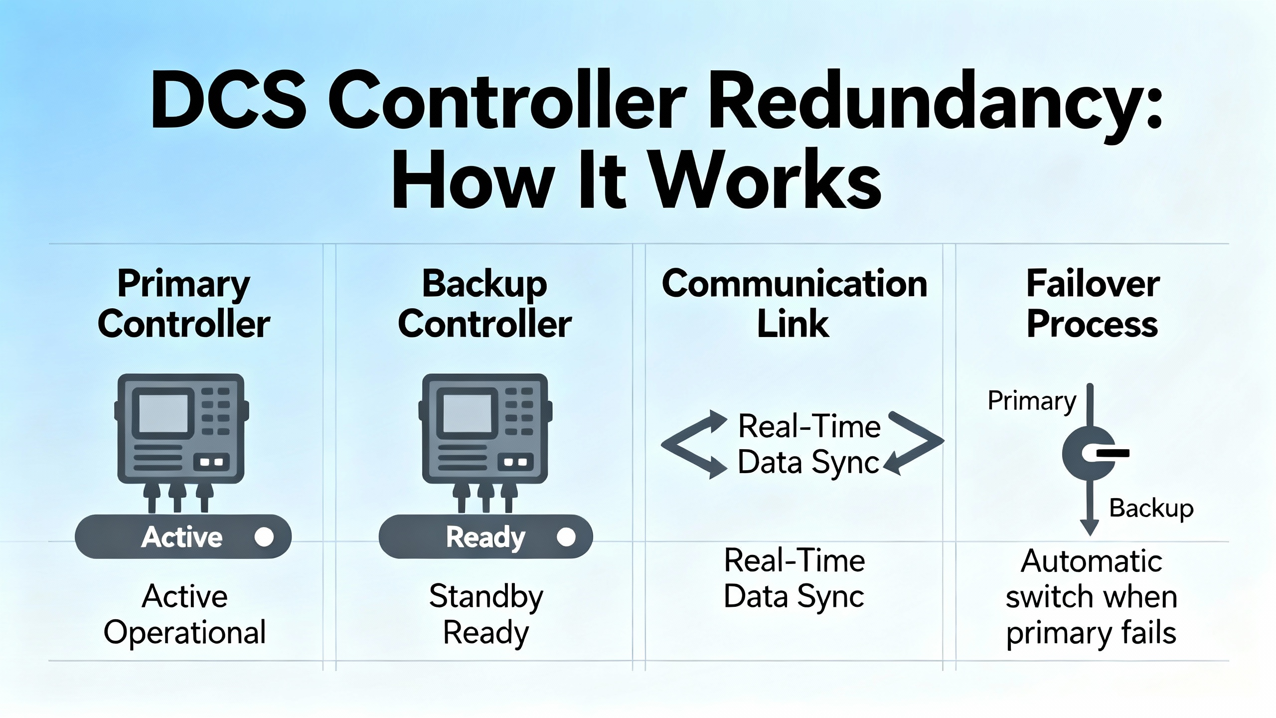
In practice, modern DCS redundancy typically spans three layers. At the controller layer, hot standby pairs or similar architectures keep a standby controller running in lockstep with the primary. If the primary fails, the standby assumes control in milliseconds. At the network layer, redundant Ethernet rings or dual independent networks reroute traffic if a switch, cable, or interface fails. At the power layer, dual power supplies, uninterruptible power supplies, and backup sources such as generators or dual utility feeds keep controllers and networking alive through disturbances.
Industry articles on redundancy, such as those from Electric Neutron and OJ Automation, describe common controller redundancy modes. Hot standby keeps the backup controller synchronized and ready to take over almost instantly, which is standard in high-availability sectors such as power generation and refining. Cold standby leaves the backup off or idle until needed, requiring more time and often some manual intervention, which is acceptable where brief downtime is tolerable. One-to-one redundancy dedicates a full backup to each controller for maximum availability, while one-to-many shares a backup across several primaries to reduce cost in less critical areas.
Another important dimension is how the switchover is triggered. ISA-focused guidance on remote control managers and DCS changeover highlights three broad modes. Manual switchover keeps a human in the loop, often reducing unintended transitions but relying on expert judgment under pressure. Automatic switchover triggers immediately on detected faults, which can achieve near-zero downtime but only if detection logic is robust and carefully tested. Hybrid approaches combine automated detection with operator confirmation or oversight, balancing responsiveness and safety.
In a healthy design, controller redundancy and these switchover strategies allow a plant to ride through a failure with only a brief disturbance. Some ISA material notes that properly configured DCS changeovers can complete within only a few seconds, during which operations may temporarily hold or “standby” processes while control passes cleanly from master to standby. The reality on the plant floor, however, often looks different.
What Redundancy Really Delivers (And What It Does Not)
A key misconception I see repeatedly is treating redundancy as a magic shield that prevents all bad outcomes. Amikong’s guidance on DCS redundancy failures captures this clearly: redundancy buys time and availability, not perfection and not guaranteed data recovery. If design, maintenance, and backup discipline are weak, a redundant system can still leave you with corrupted configurations, inconsistent states, or unsafe process conditions.
In other words, redundancy keeps the lights on long enough for your procedures and people to do their job. It does not replace sound backup strategies, nor does it negate the need for good environmental controls, cyber defenses, and structured troubleshooting. When redundant systems are treated as a safety net instead of an engineered subsystem that needs the same rigor as the base control, failover problems are almost guaranteed.
Why Redundant DCS Controllers Still Fail You
In post-incident reviews, the same patterns surface again and again. The system is marketed and documented as redundant, yet a controller failure still trips major equipment or leaves operators blind. The causes usually fall into a few familiar groups.
Misapplied Redundancy Modes
Controller redundancy modes each carry assumptions and tradeoffs, as described in resources from OJ Automation, Electric Neutron, and ISA. Problems arise when the chosen mode does not match the process risk, or when its constraints are misunderstood.
Hot standby, for example, is designed to provide seamless takeover. That only works when the standby is truly synchronized, the switchover logic is well tested, and communications between the pair are resilient. If the standby is allowed to lag or uses different application versions, the takeover can produce unexpected outputs or even lose control.
Cold standby can be perfectly acceptable in auxiliary systems or non-critical utilities, but I have seen it installed on high-value batch reactors where a manual switchover is realistically impossible under upset conditions. The design looked redundant in a drawing review, but at 2:00 AM, operators faced with multiple alarms simply could not execute the cold-standby procedure in time.
Manual, automatic, and hybrid switchovers bring their own risks. ISA-aligned guidance notes that manual changeovers rely on expert-led decisions and can reduce unwanted switches, but they also depend heavily on operator training and clear procedures. Automatic switchovers require meticulous testing, because detection logic that is too sensitive or misaligned with real failure modes can trigger transitions at the worst possible moment. Hybrid strategies add resilience but must define who has authority to override or confirm switchover, and how that interaction is logged and audited.
When these decisions are made informally or left to vendor defaults, failover behavior often surprises the very people responsible for running the plant.
Hidden Single Points of Failure
Redundancy only works if the “backup” path is truly independent. Hallam-ICS highlights painful examples from real projects: redundant power feeds that both originate from the same distribution panel, redundant network paths that share the same conduit, and multiple “redundant” controllers mounted in the same enclosure with no backup cooling. A single fire, flood, or localized overheating incident can take all of them out in one stroke.
OJ Automation’s discussion of redundancy in power and automation systems makes a similar point. Network redundancy can use ring topologies with self-healing protocols or dual independent networks, but if both network paths converge through a single switch, router, or gateway, that device becomes a single point of failure. Power redundancy can use dual power supplies, UPS units, and backup generators, but if all of that derives from one upstream transformer or physical feed with no alternative source, a grid event can still shut the entire control layer down.
Amikong’s analysis of failure causes in redundant systems adds real-world texture. Even with duplicated hardware, components such as disks, power supplies, fans, NICs, and RAID arrays still wear out. Cable terminations still loosen. Fans still clog with dust. Environmental factors such as vibration and temperature swings between about 32°F and 122°F, with relative humidity ranges from roughly 10 percent to 96 percent and vibration near 0.2 G with around 0.01 in displacement, can produce intermittent faults that easily defeat a theoretically redundant design.
If your redundancy design and physical installation do not explicitly eliminate single points of failure at the electrical, mechanical, computing, and network levels, controller failover issues are not a surprise; they are the expected outcome.
Software, Firmware, and Cyber Factors
Modern DCS controllers are as much software platforms as hardware devices. ISA’s guidance on DCS redundancy and security notes that patching DCS firmware and software is difficult because of uptime demands, but skipping patches leaves exploitable vulnerabilities and stability issues. Software and firmware that are outdated, poorly maintained, or inconsistently managed across redundant units create a rich breeding ground for failover anomalies.
Other bullets from the same ISA-oriented source emphasize that outdated software and firmware can cause inefficiency and security gaps. Recommended practices include maintaining a current software inventory, verifying licensing, updating firmware with vetted versions, and using rollback mechanisms for failed updates. When primary and standby controllers drift apart in version, configuration, or licensing status, failover behavior can become opaque and unpredictable.
Cybersecurity adds another layer of risk. Amikong’s discussion of DCS redundancy failures mentions cyberattacks, including ransomware that targets backups and control infrastructure. ISA redundancy guidance similarly warns that centralized controllers with IT connectivity increase bidirectional data-flow complexity and exposure. If malicious activity disrupts communications, alters configurations, or locks up servers, controller failover may never trigger as designed.
Because patching is constrained by uptime, many organizations adopt compensating controls: network segmentation, deep packet inspection, and virtual patching through firewalls and intrusion detection systems at IT–OT boundaries. Those protective layers directly affect whether redundant controllers can still see each other and whether failover logic can trust the information it receives.
Operational Discipline and Human Factors
In practice, many failover incidents are not caused by a single hardware or software fault but by a chain of decisions. ISA’s redundancy and troubleshooting commentary notes that failure management often prioritizes quick fixes over root cause analysis. Engineering teams are pushed to get the plant back online, which they do, but systematic diagnosis is deferred or never completed. The same issue then returns in a slightly different guise months later.
These sources recommend formal failure and RCA procedures, structured troubleshooting training, and strong collaboration with OEMs. Engineering teams that use systematic diagnostic tools and follow defined RCA workflows see fewer repeat failures, even on complex systems.
Operator behavior is equally important. The IDS Power discussion of common DCS issues identifies operator errors as a major contributor to disruptions. They recommend comprehensive training, simulation-based learning, and regular refresher courses to reduce human error. DeltaV optimization tips echo the same message, stressing ongoing operator and maintenance training, the use of simulation tools for testing strategies and alarms, and continuous monitoring of system diagnostics.
When controller failover logic and procedures are opaque to operators, or when training is treated as a one-time commissioning activity, the probability of mismanaging a failover event rises sharply.
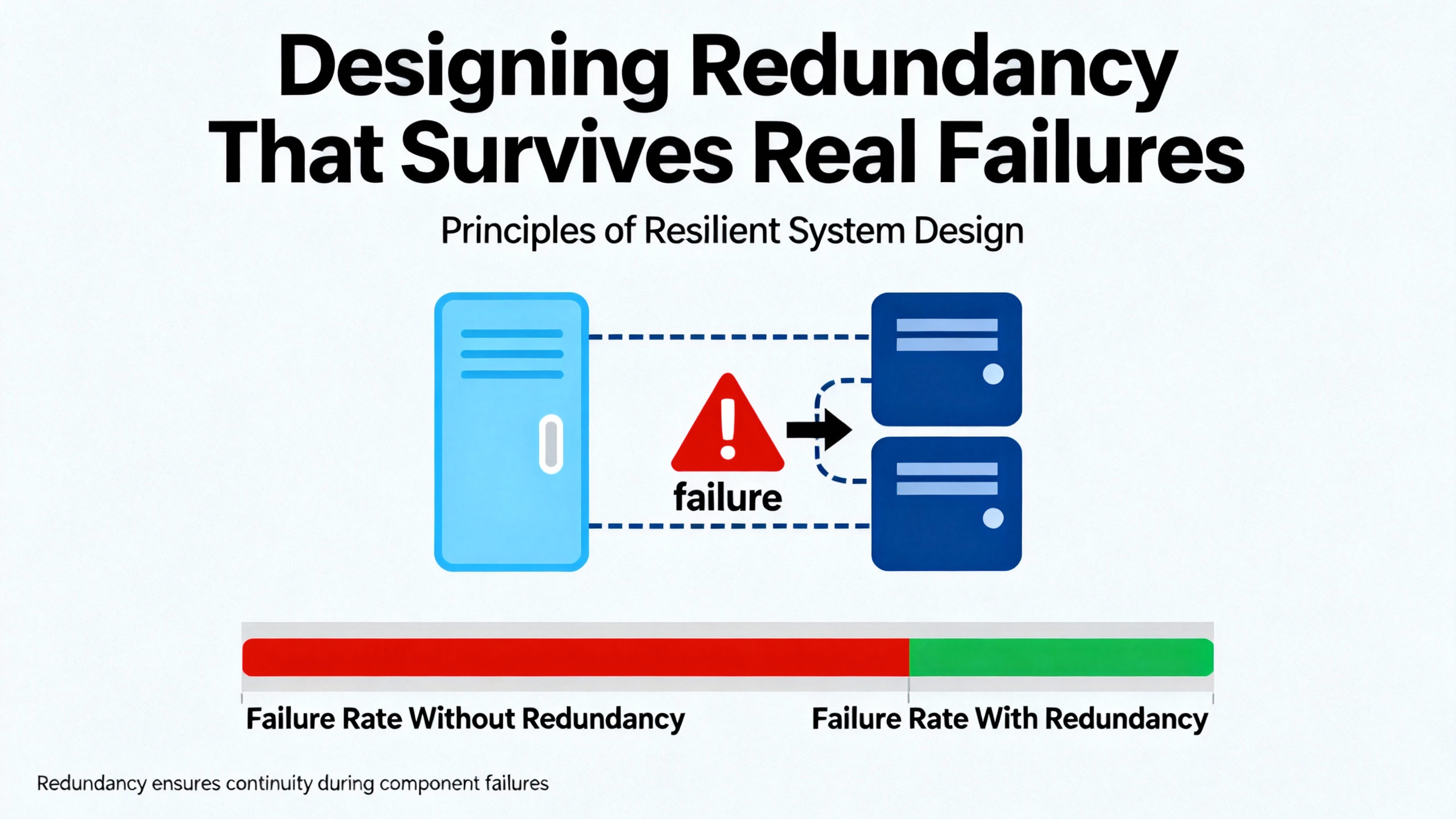
Designing Redundancy That Survives Real Failures
Fixing controller failover requires more than swapping a module. It requires stepping back and treating redundancy as an integrated design problem.
Start With a Clear Criticality and Asset Inventory
Amikong’s redundancy failure guidance and OJ Automation’s redundancy overview both emphasize the importance of an explicit inventory of critical OT and IT assets. This inventory should include controllers, remote terminal units, PLCs, servers, HMIs, historians, domain controllers that support the control environment, switches, time servers, and related infrastructure. For each, document whether it is redundant, how the redundancy works, and how health and synchronization are monitored.
Hallam-ICS advises starting redundancy planning with a top-down site review rather than jumping straight into hardware selection. This includes security systems, utilities, safety systems, HVAC and process utilities, ventilation, IT infrastructure, and the automation layer. The goal is to identify single points of failure and decide where redundancy truly matters based on system criticality, acceptable downtime, cost of downtime versus redundancy investment, environmental conditions, regulatory requirements, and historical failure data.
OJ Automation specifically warns against blanket redundancy everywhere. The best practice is to apply redundancy selectively where failure would have significant safety, environmental, or economic impact.
Choose the Right Controller Redundancy and Switchover Strategy
The next step is choosing redundancy modes that match the real risk and operational culture.
For high-consequence processes such as refining, power generation, or pharmaceutical manufacturing, sources like Electric Neutron and OJ Automation show that hot standby pairs and one-to-one redundancy on key controllers are common, often combined with voting architectures in safety layers. These sectors cannot tolerate long outages or difficult restarts, so near-instantaneous switchover and high diagnostic coverage are essential.
In lower-risk areas or auxiliary systems, cold standby or one-to-many redundancy may be sufficient. These setups reduce hardware cost but increase recovery time. They are suitable only when brief interruptions do not damage equipment and the restart path is straightforward.
ISA’s discussion of manual, automatic, and hybrid changeover then shapes how failover is orchestrated. Critical loops with limited operator reaction time usually require automated switchover, with hybrid oversight to avoid spurious transitions. Systems where the cost of a mistaken switchover is high relative to a brief manual intervention may favor manual or hybrid approaches, provided the procedures are drilled and realistic.
The key is to make these decisions explicit, document the rationale, and ensure everyone from engineering to operations understands what will happen when a controller fails.
Architect Power and Networks for Real Independence
Hallam-ICS offers very practical warnings about redundancy that exists only on paper. To avoid those traps, redundant power and network paths must be physically and electrically independent.
On the power side, OJ Automation recommends dual power supplies in control panels, UPS units for short-term backup, backup generators for extended outages, and redundant transformers or dual feeds from separate substations for critical loads. Amikong’s case-study guidance suggests keeping typical operating loads on controllers and power supplies below roughly forty percent and network loads below about fifty percent, with memory usage leaving at least half capacity free. These operating margins provide resilience when one leg of a redundant pair is lost and the other must temporarily carry more load.
On the network side, both Electric Neutron and OJ Automation describe redundant Ethernet rings and dual networks, often using industrial protocols and self-healing mechanisms. ISA adds that high port traffic from SCADA, PLCs, and switches can degrade performance and increase cyber risk. Recommended mitigation includes network segmentation, deep packet inspection, and regular auditing and securing of open ports. For failover specifically, redundant networks must avoid shared bottlenecks, such as single aggregation switches or shared fiber paths, that turn an apparent dual network into a single vulnerable spine.
Configure and Monitor Controller Redundancy Proactively
Even the best hardware architecture fails if the configuration is wrong or if health indicators are ignored. ISA’s redundancy article highlights the need for continuous monitoring of master and standby units, real-time health checks, confirmation of intercommunication, and alerts for synchronization or connectivity issues. Those checks are the first line of defense against a redundancy pair silently degrading into a de facto single controller.
Vendor-specific diagnostics, as referenced in DeltaV optimization tips, provide valuable insight into controller status, communication quality, and failover readiness. Using those tools to track trends, set thresholds, and trigger alarms on early warning signs can prevent hidden issues from surfacing only during a real failure.
Configuration discipline matters as well. Guidance on DCS configuration from sources like Just Measure it emphasizes consistent naming, structured tag hierarchies, documented control narratives, and control of configuration changes through versioning and approvals. For redundancy, that translates into ensuring primary and standby controllers share the same verified logic, alarm definitions, and firmware, and that configuration changes follow a process which updates both sides under change control with the ability to roll back if needed.
A Practical Path To Fixing DCS Controller Failover in an Existing Plant
When I am called into a plant that has just suffered a controller failover incident, the approach is methodical. The technology may be modern, but the fundamentals are straightforward.
Stabilize the Process and Make the Plant Safe
Amikong’s restoration guidance states that the first step after a redundancy failure is to stabilize the process and make the plant safe before attempting to repair or re-establish redundancy. That means protecting people, equipment, and the environment.
The initial actions are usually confirming that protective functions, alarms, trips, and interlocks are still operational; shifting to local or manual control for critical equipment if necessary; and ensuring that emergency shutdown paths are available. Only once the process is in a safe, stable state should the team begin hands-on work on the redundant controllers or networks.
Reconstruct the Failover Timeline Using Data
The next task is reconstructing what happened. The LinkedIn discussion on measuring and benchmarking DCS redundancy emphasizes collecting and analyzing data such as availability, reliability, maintainability, mean time between failures, mean time to repair, failure rates, and failure modes. The same principle applies during post-incident analysis.
Data sources typically include controller and server logs, alarm histories, event journals, network diagnostics, and audit trails. Tests, simulations, and structured root cause analysis then help distinguish between the initiating fault, contributing conditions, and the behavior of the redundancy mechanisms themselves.
The goal is to answer concrete questions. Was the standby healthy and synchronized before the event? Did inter-controller communications or network paths degrade? Did the system attempt a switchover and fail, or never attempt one at all? The answers drive the fix.
Compare the Documented Design With Physical Reality
Amikong and Hallam-ICS both recommend having a clear, documented view of system architecture. In remediation work, I always compare this documentation to the plant as found. Discrepancies are common.
This comparison includes verifying where redundant power feeds truly originate, how network cables are physically routed, where switches and routers are located, and how controllers are grouped in enclosures. It also involves cross-checking controller redundancy configuration, licensing status, and firmware versions between primary and standby.
Hallam-ICS warns about common design shortcomings: redundant power and network feeds that share the same panel or raceway, unnecessary intermediate switches that become single points of failure, and colocating too many redundant components in the same high-temperature enclosure without backup cooling. All of these flaws are easy to miss in paper design reviews and almost always show up when you walk the plant with drawings in hand.
Address Infrastructure and Configuration Gaps
Once the root causes and architectural gaps are understood, remediation usually falls into a few categories.
Physical and electrical fixes may involve re-routing redundant power feeds to different distribution sources, separating network cabling for primary and redundant paths into different routes, or adding environmental protections such as better ventilation or vibration mitigation where Amikong’s environmental limits are being exceeded. Sometimes it means relocating controllers or network equipment so that a single localized event cannot disable both redundant legs.
Configuration changes are just as important. This can include tightening redundancy health thresholds, enabling or correcting synchronization checks between master and standby controllers as ISA recommends, aligning firmware and software versions across redundant pairs based on vendor recommendations, and cleaning up abandoned or inconsistent configuration fragments that confuse failover logic.
Security and patch management measures, as described in the ISA redundancy guidance, may also be part of the fix. This can mean segmenting networks more strictly, implementing deep packet inspection, and planning controlled patch windows with testing in isolated environments and rollback mechanisms. Where immediate patching is not feasible, virtual patching via firewalls and intrusion detection helps control risk.
Test Failover Under Controlled Conditions
Restoring redundancy on paper is not enough. Organizations such as Microsoft, when advising on Active Directory server redundancy, recommend controlled failover tests: move roles, isolate a primary, and verify that secondary servers take over without disrupting services. The DCS world should demand the same discipline.
Electric Neutron and OJ Automation both stress that backup systems must be tested and maintained regularly to ensure seamless failover. ISA notes that DCS changeovers should be robustly tested because they usually need to achieve near-zero downtime and may last only a few seconds.
In practice, a controlled DCS failover test is coordinated across operations, maintenance, and engineering. The process is put in a safe, stable state; operators are briefed on expected behavior; and the team deliberately forces a controller failover via vendor-approved methods. Throughout the test, they watch for process responses, diagnostic alarms, failover times, and any unexpected behaviors. The test is documented, and any anomalies lead to further tuning and, if necessary, additional rounds of testing.
Institutionalize Monitoring, RCA, and Training
The last step is turning a one-off remediation into a sustained improvement program. ISA’s redundancy guidance recommends formal failure and RCA procedures, close collaboration with OEMs, and systematic troubleshooting training. DeltaV optimization sources reinforce the value of ongoing training, simulations for testing changes, and continuous monitoring of diagnostics and performance metrics.
Embedding these practices means creating and maintaining documentation such as cause-and-effect matrices, network diagrams, alarm philosophies, and redundancy design descriptions. It also means scheduling regular health checks, trend reviews, and failover tests, and integrating redundancy performance into plant KPIs.
When a controller failover issue is treated as a process event requiring investigation and learning rather than an annoyance to be patched quickly, the resilience of the entire DCS improves.
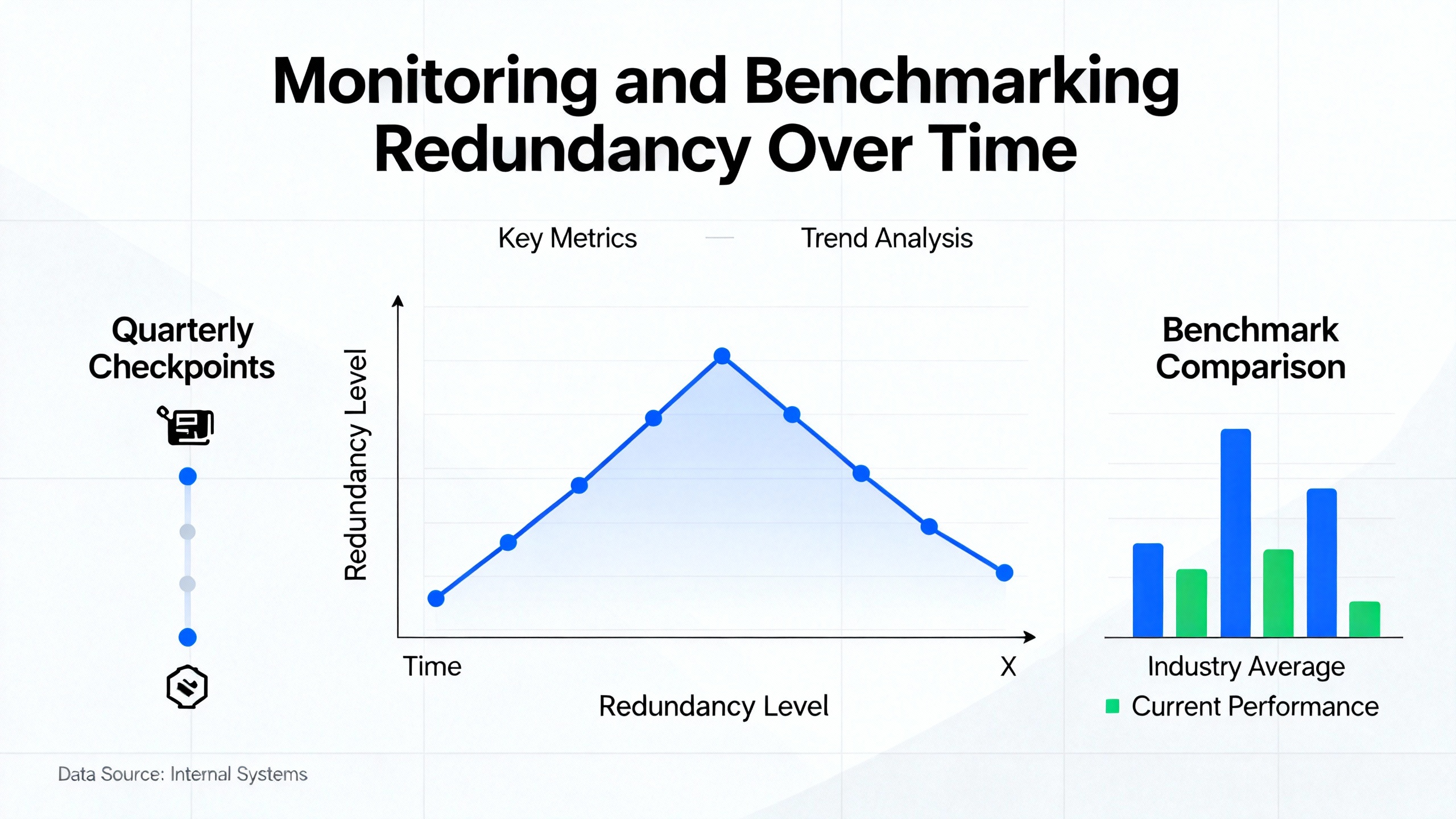
Monitoring and Benchmarking Redundancy Over Time
Sustainable reliability depends on measuring the right things. The LinkedIn discussion of benchmarking DCS redundancy lists several core metrics and analysis methods. ISA guidance adds continuous monitoring of master and standby health. Combining these ideas produces a practical monitoring scheme.
The following table summarizes key redundancy metrics and how they are typically used.
| Metric | What It Indicates | Typical Data Source |
|---|---|---|
| Availability | Proportion of time control functions are available | System logs, historian, uptime reports |
| Reliability | Likelihood the system performs correctly over a given period | Failure histories, trend analysis |
| MTBF | Average operating time between failures | Maintenance records, event logs |
| MTTR | Average time to restore service after a failure | Work orders, incident reports |
| Failure rate | Frequency of failures over time | Combined incident and runtime data |
| Failure modes | Ways in which controllers and redundancy paths fail | Root cause analyses, vendor diagnostics |
| Failover duration | Time between fault detection and stable takeover | Redundancy event logs, test measurements |
| Sync health | Quality and consistency of master–standby synchronization and communications | Controller diagnostics, redundancy alarms |
Data collection can draw on sensors, logs, alarms, reports, audits, tests, simulations, and formal root cause analysis, as suggested in the LinkedIn guidance. ISA’s emphasis on monitoring synchronization and connectivity reinforces the importance of using controller-level diagnostics alongside higher-level performance metrics.
The intent is not to drown engineering in numbers, but to provide evidence that redundancy mechanisms are functioning as designed and that any drift is caught early rather than during a process upset.
Security and Governance Around Failover
Redundancy and security are tightly linked. ISA articles on DCS redundancy and security caution that centralized controllers with IT connectivity increase bidirectional data-flow complexity and security exposure. Their recommendations include enforcing one-way data paths where possible, deploying firewalls and intrusion detection at IT–OT boundaries, and tightly governing centralized access to control software.
These sources advise that real-time access to PLC, SCADA, and industrial switch software should be allowed only from secured locations, through secure access gateways for remote troubleshooting, with all remote sessions monitored and strict authorization enforced. In practical terms, this means that failover controls, redundancy configuration tools, and engineering workstations must be protected as carefully as safety systems.
Cyber incidents that disrupt controller communications, corrupt configuration data, or hijack backup servers can compromise both primary control and redundancy. Defense-in-depth practices, aligned with frameworks such as IEC 62443 and ISA standards referenced by Electric Neutron, are essential safeguards for the availability that redundancy is meant to provide.
FAQ
How often should I test DCS controller failover?
Industry guidance from both control-system integrators and IT redundancy practices emphasizes that redundancy testing should be repeated periodically, not treated as a one-time commissioning activity. The precise frequency depends on process criticality, regulatory expectations, and how frequently you change controllers, networks, or software. At minimum, you should run controlled failover tests after any significant change in hardware, firmware, network design, or redundancy configuration, and schedule recurring tests often enough that knowledge and procedures stay fresh for both engineering and operations.
Do I really need full redundancy on every controller?
Sources such as OJ Automation and Hallam-ICS argue against defaulting to full duplication everywhere. Instead, start with a criticality assessment. Apply robust controller, network, and power redundancy where failure would pose serious safety, environmental, or economic impacts. In less critical areas, you may choose simpler architectures, fail-safe designs, or procedural mitigations. The combination of Amikong’s recommendation to inventory critical assets and OJ Automation’s advice to selectively apply redundancy often leads to a more cost-effective and reliable system than blanket duplication.
Is process simulation or a digital twin worth the effort for redundancy?
ISA’s redundancy guidance points to digital twins and simulation as powerful tools for troubleshooting and downtime mitigation in complex systems. In practice, if your plant already uses simulation for operator training or control strategy testing, extending it to failover scenarios can be very valuable. You can rehearse controller failures, network outages, and changeover procedures without risking real equipment. For large or highly integrated plants, this often provides the safest way to test edge cases that are impractical to reproduce on the live system.
Closing Thoughts
When a redundant DCS trips a unit instead of saving it, the problem is rarely a single bad module. It is usually a design and governance issue that spans controllers, networks, power, software, and people. By treating redundancy as an integrated engineering discipline, grounding decisions in documented standards and vendor guidance, and relentlessly testing and measuring failover behavior, you can move your system from “redundant on paper” to truly resilient. That is the level of reliability most plants believe they have; it is achievable, but only with deliberate, sustained effort.
References
- https://blog.isa.org/ensuring-rcm-or-dcs-redundancy-and-its-security-in-a-complex-industrial-environment
- https://automationcommunity.com/dcs-maintenance/
- https://www.chuwntek.com/news/how-to-improve-distributed-control-system-reliability.html
- https://www.electricneutron.com/dcs-redundancy/
- https://www.hallam-ics.com/blog/so-you-need-control-system-redundancy
- https://idspower.com/common-issues-control-systems/
- https://www.linkedin.com/pulse/best-practices-dcs-engineer-zohaib-jahan
- https://ojautomation.com/content/redundancy-in-industrial-power-and-automation-systems
- https://www.wevolver.com/article/mastering-distributed-control-systems-a-comprehensive-guide-to-dcs-architecture-components-and-applications
- https://zeroinstrument.com/general-procedures-for-routine-maintenance-and-troubleshooting-of-dcs-systems/
Keep your system in play!
Top Media Coverage
Categories


Related articles Browse All
-
 amikong NewsSchneider Electric HMIGTO5310: A Powerful Touchscreen Panel for Industrial Automation2025-08-11 16:24:25Overview of the Schneider Electric HMIGTO5310 The Schneider Electric HMIGTO5310 is a high-performance Magelis GTO touchscreen panel designed for industrial automation and infrastructure applications. With a 10.4" TFT LCD display and 640 x 480 VGA resolution, this HMI delivers crisp, clear visu...
 -
 BlogImplementing Vision Systems for Industrial Robots: Enhancing Precision and Automation2025-08-12 11:26:54Industrial robots gain powerful new abilities through vision systems. These systems give robots the sense of sight, so they can understand and react to what is around them. So, robots can perform complex tasks with greater accuracy and flexibility. Automation in manufacturing reaches a new level of ...
 -
 BlogOptimizing PM Schedules Data-Driven Approaches to Preventative Maintenance2025-08-21 18:08:33Moving away from fixed maintenance schedules is a significant operational shift. Companies now use data to guide their maintenance efforts. This change leads to greater efficiency and equipment reliability. The goal is to perform the right task at the right time, based on real information, not just ...


- Q&A
- Policies How to order Part status information Shipping Method Return Policy Warranty Policy Payment Terms
- Asset Recovery
- We Buy Your Equipment. Industry Cases Amikong News Technical Resources Why choose us
- ADDRESS
-
 32D UNITS,GUOMAO BUILDING,NO 388 HUBIN SOUTH ROAD,SIMING DISTRICT,XIAMEN
Leave Your Comment