
-
Please try to be as accurate as possible with your search.
-
We can quote you on 1000s of specialist parts, even if they are not listed on our website.
-
We can't find any results for “”.
Emergency Shutdown System Malfunction: Critical Troubleshooting
Why Emergency Shutdown Failures Matter More Than Ordinary Breakdowns
In most plants, a failed pump or a worn belt is inconvenient. A failed emergency shutdown system is something else entirely. Emergency shutdown systems exist to keep a bad day from becoming a fatal one. They are the last automated barrier between abnormal conditions and serious harm to people, assets, and the environment.
An emergency shutdown system, often called an ESD within a safety instrumented system, continuously watches critical process parameters and, when predefined limits are exceeded, drives the plant or unit to a safe state. In hazardous locations such as Class I Divisions, where flammable gases or vapors can form explosive mixtures, these systems are treated as essential safeguards rather than optional add‑ons. Industry guidance from safety specialists emphasizes that ESDs protect lives and production continuity at the same time by preventing escalation of incidents.
The financial stakes are significant. A recent industrial maintenance report cited in emergency maintenance guidance estimates unplanned downtime at roughly $25,000.00 per hour on average, with some large operations exceeding $500,000.00 per hour. On top of that, emergency maintenance articles in Occupational Health & Safety and other publications remind us that unscheduled, high‑pressure repair work is exactly where people are most tempted to cut corners.
From a regulatory standpoint, agencies such as OSHA in the United States, the Health and Safety Executive in the United Kingdom, and standards bodies such as ISO, IEC, and the ESD Association all converge on the same message. Employers must identify hazards, design controls—including emergency shutdown and stopping functions—plan for emergencies, train their people, and maintain these systems so they work on demand.
When an emergency shutdown system misbehaves, you are dealing with a safety instrument, not just a convenience. Troubleshooting is no longer about getting the line running again at any cost. The goal is to restore a proven, predictable safety function, and document that it will behave correctly the next time it is needed.
Emergency Stop Versus Emergency Shutdown
A common source of confusion during troubleshooting is the difference between an emergency stop and an emergency shutdown.
An emergency stop, often called an E‑stop, is a manual, complementary protective measure. It is typically a red button or pull cord that directly interrupts control power to a specific machine or production section. ISO 13850 and ISO 13849‑1 require these systems to achieve at least Performance Level c under defined architectures. Machinery safety experts such as Douglas Nix emphasize that an E‑stop must override all other controls, stop hazardous motion as quickly as reasonably possible, and never allow automatic restart. After activation, control power remains removed until an intentional reset or power‑on action.
An emergency shutdown system acts at a wider scale. As described in industrial control guidance and case studies from refineries and power plants, a properly designed ESD can shut down an entire process segment or facility. The logic solver, often a safety PLC, evaluates input from field instruments and decides which valves to close, which pumps to stop, how to depressurize equipment, and how to manage ventilation so that the process reaches a safe state without creating new hazards. Modern temperature‑aware control panels even integrate temperature limits directly into shutdown logic so that high‑temperature excursions can trigger safe, staged shutdown rather than equipment damage.
A simple way to distinguish them is that an E‑stop is a local, manual last‑resort control for a piece of equipment, while an ESD is a coordinated safety function for a process. Both can malfunction, but the mechanisms and troubleshooting approaches differ.
The table below summarizes key differences that matter during troubleshooting.
| Aspect | Emergency Stop (E‑stop) | Emergency Shutdown (ESD) |
|---|---|---|
| Typical scope | Single machine or production cell | Process unit, area, or entire facility |
| Activation | Manual, by operator | Automatic via safety logic, sometimes with manual initiation |
| Main function | Immediately remove control power to stop motion | Drive the process to a defined safe state in a controlled sequence |
| Design basis | Machinery risk assessment, ISO 13850 and ISO 13849‑1 performance levels | Process risk assessment, functional safety principles, SIL targets for safety functions |
| Restart behavior | Never automatic; requires reset and start action | Restart governed by operating procedures and safety system reset logic |
Understanding which function you are dealing with is the first step toward efficient troubleshooting.
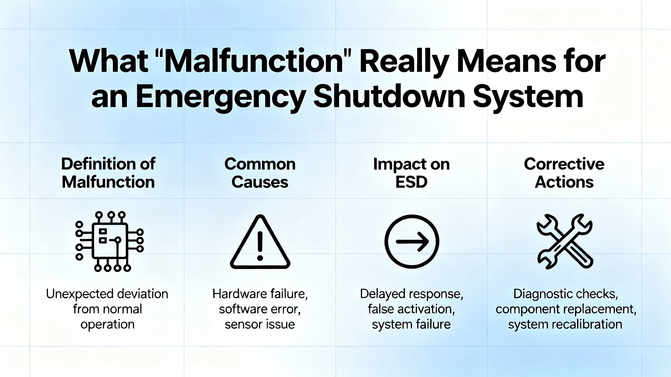
What “Malfunction” Really Means for an Emergency Shutdown System
In a plant context, an emergency shutdown malfunction is not just “the system did not work.” It usually falls into one of several recognizable patterns.
Sometimes the system fails dangerously by not acting when it should. A classic example is an ESD valve that fails to close during a trip test. Research based on OREDA reliability data and Failure Modes, Effects, and Diagnostic Analysis of ESD valves in the oil and gas sector shows that failures in these final elements are among the most critical within the entire ESD chain. The same FMEDA work concludes that the actuator subsystem is the dominant contributor to safety risk, which matches what many practitioners see in the field.
Other times the malfunction is a nuisance trip or spurious shutdown. Emergency maintenance and shutdown maintenance articles point out that while such events are safer than a failure to trip, they still disrupt operations, drive costs, and erode confidence in the system. Common causes include faulty sensors, wiring issues, and electromagnetic disturbance.
Emergency stop systems bring their own failure modes. Machinery safety guidance documents many cases where the E‑stop appears to operate but does not fully remove control power, or where machines restart when the E‑stop is reset without a deliberate start command. These are considered failed tests and must trigger corrective action.
Finally, in modern, PLC‑based emergency systems, control platforms themselves can be part of the problem. Industrial control guidance identifies input or output module failures, erratic power supply between roughly 5 and 24 V, electromagnetic or radio‑frequency interference, corrupted memory, and loss of communications as common causes of PLC malfunction. When those platforms host or supervise the ESD logic, troubleshooting must include them, not only the field hardware.
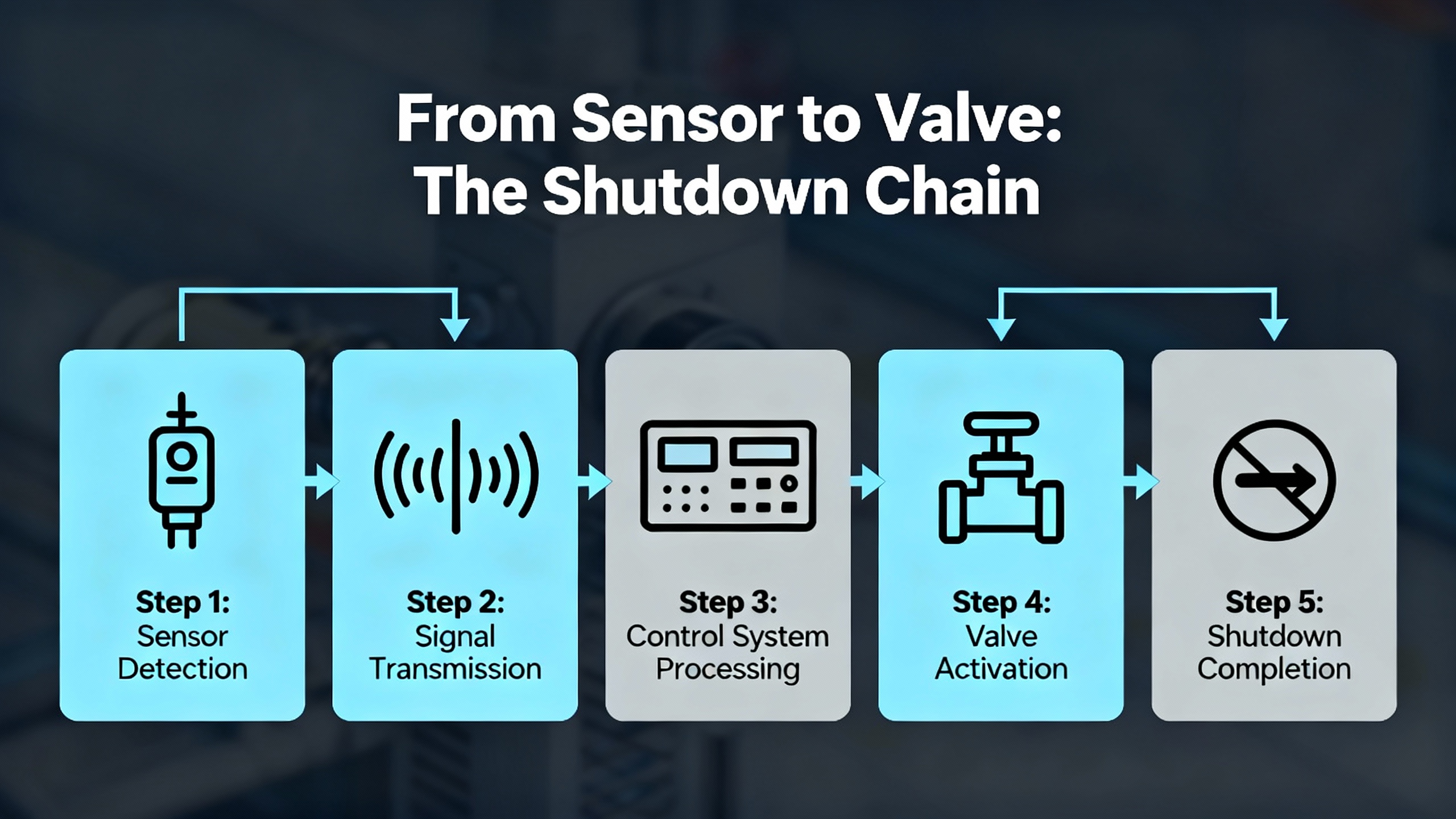
From Sensor to Valve: The Shutdown Chain
Every emergency shutdown function can be viewed as a chain of elements that must all work correctly.
It starts with detection. Level switches, pressure switches, temperature transmitters, fire and gas detectors, and manual trip stations provide the first indication that something abnormal is happening. Articles on on–off and shutdown valve troubleshooting highlight that safety interlocks based on these devices can intentionally block valve motion when configured to do so. A stuck pressure switch or faulty level switch may prevent the system from issuing a valid shutdown command, or may hold a permissive that should have cleared.
Next comes the logic solver. In many facilities this is a safety‑rated PLC with its own input and output modules. It receives the signals, evaluates them against programmed logic, and drives outputs to solenoid valves, contactors, and other final elements. Powerblanket’s explanation of PLC operation describes a continuous cycle of scanning inputs, executing logic, and updating outputs. That cycle becomes a safety engine in an ESD application, continuously monitoring for trip conditions and acting when they occur.
Finally, the shutdown command must reach the final elements. For an ESD valve, this usually involves a solenoid‑operated valve, instrument air at about 80 to 100 psi derived from the 5.5 to 7 bar figures in troubleshooting guides, pneumatic or hydraulic actuators, and the valve body. Any weakness in this chain can result in sluggish motion, partial closure, or complete failure to move.
Alongside ESD valves, emergency stops, power isolation contactors, and auxiliary systems such as emergency ventilation or hydrocarbon inventory isolation valves are also part of the overall shutdown response. If a fire event occurs, PLC‑based emergency ventilation systems may open dampers, close fire doors, or shut down fans while the ESD closes process valves and trips pumps.
Understanding this chain from sensor to valve clarifies where to look first when something goes wrong.
Field‑Proven Approach to an ESD Valve That Will Not Close
When an ESD valve fails a trip test or does not close as expected in a real demand, the safe, systematic approach is to treat it as a multi‑discipline investigation across logic, electrical, pneumatic, and mechanical domains. Linked guidance from shutdown valve troubleshooting sources and a step‑by‑step breakdown from an experienced practitioner on a professional network outline a practical path.
Begin by confirming the symptom and the demand. Verify that the test procedure or real trip condition genuinely called for the valve to move and note whether it did not move at all, moved only partially, or moved too slowly. This simple observation will guide the rest of the troubleshooting.
Then verify that the logic actually issued a trip. In the safety PLC or dedicated ESD logic, confirm that the initiating cause became true, that any permissives were satisfied, and that no interlocks or latching functions intentionally blocked the trip. Some shutdown valves are operated via latching solenoids or mechanical latching mechanisms; those must be in the correct state before movement can occur. Configuration issues are easy to overlook: a loop left in manual mode or a forced output in the DCS or PLC can mask real failures or prevent automatic action.
Once the logic side is clear, move to the electrical circuit feeding the valve’s solenoid. Guidance from instrumentation troubleshooting notes and the ESD valve failure article is consistent: use a multimeter to check for the correct trip voltage at the solenoid coil terminals whenever the trip should be active. If the expected 24 VDC or 48 VDC signal is missing, work upstream through field junction boxes, marshaling cabinets, fuses, relays, and card terminals until the break is found. Loose terminations, blown fuses, faulty relays, and rare but real digital output channel failures all show up in this part of the chain.
If the proper voltage is present, confirm the solenoid coil is healthy. Measure its resistance and compare it with manufacturer data. A coil that reads open, shorted, or significantly out of range is suspect and should be replaced. Some practitioners also temporarily energize the coil manually while monitoring the valve response, but this must be done under strict lockout and permit control when dealing with safety systems.
With the electrical signal in order, focus on the instrument air or hydraulic supply. Both the on–off valve troubleshooting guide and the LinkedIn ESD valve analysis stress the importance of verifying that supply pressure at the actuator and solenoid meets the datasheet requirement. For typical instrument air systems this means confirming roughly 80 to 100 psi at the relevant ports. Inspect air regulators, filters, and headers for failures or drift, and look for leaks in tubing and fittings that could bleed pressure away during a trip.
Next, confirm that the solenoid valve and actuator actually move and vent as intended. Where procedures allow, operate the solenoid manually and observe actuator movement. Listen and feel for air escaping where it should not, examine the actuator diaphragm or piston for leakage, and check that spring return mechanisms are not broken or binding. Travel stops and stroke adjustments can be mis‑set in ways that prevent full closure even when the actuator appears to move.
Only after electrical and pneumatic aspects have been cleared should attention shift to the valve body itself. Mechanical sticking from debris, corrosion, or seat damage can prevent movement. A common technique recommended in shutdown valve troubleshooting resources is to apply direct air and cycle the valve several times, watching for gradual improvement. If cycling does not restore free motion, a full valve overhaul is usually required. If the valve moves freely under direct air but misbehaves in process service, consider internal issues that appear only under pressure or temperature, such as internal galling or thermal distortion.
Throughout this process, verify that valve position feedback devices—limit switches, position transmitters, proximity sensors—are correctly set and wired. Faulty feedback can cause the ESD logic to believe the valve is already closed or open, masking a real failure or causing inappropriate alarms. After corrective actions, repeat the full functional test. Observe stroke time, confirm that the valve reaches its safe position on demand and on loss of air if required, and document the results.
All of this must be done under robust safety management. Safety recommendations emphasize lockout–tagout, coordination with the control room, and strict rules for bypassing ESD logic during tests. At the end of the work, every safety function that was disabled or inhibited must be fully restored and recorded.
Troubleshooting the Logic Solver and Power Infrastructure
Not every shutdown malfunction is caused by a field device. PLC‑based emergency systems introduce their own failure modes, and ignoring them can leave you chasing symptoms instead of causes.
Industrial controls guidance identifies input or output module failure as a frequent offender. When an output card fails, the safety PLC may continue to execute logic correctly, but the shutdown command never reaches the solenoid. Conversely, a stuck or noisy input card can report phantom trips or mask true ones. If all field checks appear normal, reviewing diagnostic data from the PLC, including health bits for I/O modules and error logs, becomes essential.
Power quality is another recurring theme. PLCs typically run between about 5 and 24 V, and articles on emergency PLC shutdown systems warn that brownouts, surges, and complete blackouts can all cause trouble ranging from brief glitches to permanent damage. In an ESD context, power loss can cause the system to revert to default states or lose its program entirely if backup arrangements are inadequate. Recommended mitigations include installing uninterruptible power supplies, using generator backup where appropriate, and programming the PLC with a battery time‑out function so it fails in a controlled way rather than unpredictably.
Electromagnetic interference and electrostatic discharge can also upset logic. Technical discussions on ESD and Electrical Fast Transient testing show how high‑frequency transients can couple into power supplies and I/O, sometimes causing operating systems to crash or protection circuits to trip. On a motherboard, these events may manifest as blue screens. In an industrial ESD, they may show up as spurious trips, frozen inputs, or lost communication with remote I/O.
Bench‑top EMC experts emphasize that the key to solving these issues is understanding the ESD current path and then designing or retrofitting robust return paths, shielding, and filtering. On the plant floor, that translates into careful bonding of cable shields, properly rated common‑mode chokes and surge suppressors in power supplies, transient protection on I/O, and minimizing ground path inductance so return currents are diverted away from sensitive logic.
From a troubleshooting standpoint, if you suspect an ESD malfunction had an electromagnetic cause—for instance, coincident with lightning storms, large motor starts, or welding in the area—it is reasonable to review grounding measurements, inspect for loose bonding straps, and evaluate whether current protective devices such as transient voltage suppressors and line filters are adequate.
Emergency Stop Circuits: Small Devices, Big Consequences
While the main focus of this discussion is automated emergency shutdown, no practical troubleshooting guide can ignore emergency stop systems. When these manual devices fail, the risk is immediate and personal.
Machinery safety guidance describes emergency stops as non‑automatic, complementary protective measures whose reliability targets are derived from risk assessment. ISO 13850 requires that they reach at least Performance Level c under ISO 13849‑1, with higher risk situations requiring more robust categories.
In the field, a non‑functioning E‑stop usually shows up one of two ways. Either pressing the button fails to stop hazardous motion, or the machine restarts automatically when the E‑stop is reset without an explicit start command. Both outcomes violate key requirements. Under ISO 13850, hazardous movements must stop in an appropriate way without further human intervention, and no intentional or unintentional start commands may take effect until the system is reset and a proper start request is given.
Practical troubleshooting of a suspect E‑stop begins with basic visual and electrical checks, similar to those described in industrial how‑to articles. Inspect the button for physical damage, tampering, or loose connections. Confirm the power supply feeding the E‑stop circuit is present. Use a meter to verify that normally closed contacts actually open when the button is pressed. If behavior deviates from the expected pattern, the device should be replaced rather than repaired in a questionable way.
The wider control circuit must also be examined. Relays, contactors, and safety relays can develop pitted contacts or internal faults that bypass or defeat the intended stop function. For systems integrated with PLCs, configuration mistakes or overlooked diagnostic messages can disable or misinterpret the E‑stop input. Environmental conditions such as excessive humidity, dust, or heat can accelerate wear and corrosion, so assessing the installation environment is part of reliable troubleshooting.
As with ESDs, every E‑stop device on a machine must be individually tested. Any device that fails to generate the emergency stop condition is counted as a failed test and must trigger corrective action. Where organizations perform advanced testing under electromagnetic interference conditions, they may catch subtle failures that only occur during disturbance, but even basic functional tests already reveal a large class of problems.
When Static and Transients Damage the Safety Chain
Electrostatic discharge and related transient phenomena are frequent silent contributors to emergency system malfunctions. They can damage components outright or leave them only partially functional, resulting in intermittent faults that are difficult to reproduce.
On assembly and SMT lines, ESD Association experts point out that proving a specific failure was caused by an ESD event is complex and often requires specialized failure analysis. Because of that, industry best practice is to focus on prevention rather than post‑failure forensics. Standards such as ANSI and ESDA technical reports guide grounding of conductive objects, the use of ionizers to neutralize insulators, and the need for static‑shielding packaging. Monitoring tools such as ESD event detectors and ESD audit kits help verify that control measures are actually effective.
For completed electronics, discussions about ESD and Electrical Fast Transient immunity in motherboard and power supply design show how these impulses have broad frequency content and can cause subtle power rail or ground disturbances. Requirements for ESD immunity testing, such as the IEC 61000‑4‑2 test sequence of repeated positive and negative discharges, exist exactly because these effects are both common and non‑intuitive.
From the standpoint of an emergency shutdown system, ESD and EFT‑induced problems can appear as sporadic trips, unexplained input changes, or damaged I/O channels. While the research notes focus on general EMC methods rather than ESD‑specific ESD valves, the principles carry over. Ground paths must be low impedance, shielding and layout must guide surge currents around sensitive circuits, and transient suppression devices must be chosen and located to clamp energy before it reaches safety PLC inputs or sensor electronics.
When troubleshooting ESD‑related safety issues, it is important to differentiate between permanent damage and soft upsets. If swapping a suspected chip consistently restores function, as described in field reports of sensitive transceivers, that points toward damage. If behavior recovers after a power cycle and leaves no permanent signs, it may be a transient upset. In either case, improving ESD control in manufacturing and reinforcing EMC design in the installed system are the long‑term answers.
Reliability, FMEDA, and the Priority of the Actuator
Restoring operation after a malfunction is only part of the job. The next question is how to prevent the same failure from recurring. Here is where reliability analysis and functional safety metrics become essential.
Researchers applying FMEDA techniques to ESD valves in oil and gas systems decomposed the valve into subsystems, catalogued failure modes, and classified them based on criticality and detectability. Using failure rate data and diagnostic classifications, they calculated metrics such as Safe Failure Fraction and mapped subsystem performance to Safety Integrity Level requirements. One of the most practical findings from that work is that the actuator subsystem dominates overall risk and reliability concerns for ESD valves.
This observation aligns well with field experience and troubleshooting guides that repeatedly highlight actuator and solenoid problems as prime suspects when valves misbehave. From a maintenance planning standpoint, it means periodically testing and overhauling actuators, verifying solenoid operation, and checking air or hydraulic supplies is not just good practice; it is the main way to maintain the risk reduction claimed on paper.
Valve selection and certification also matter. Specialists in petrochemical valve safety emphasize that emergency shutdown valves are designed to fail to a safe state, typically closed, when control power or instrument air is lost. International Electrotechnical Commission standards define Safety Integrity Levels from SIL‑1 through SIL‑4. Many ESD valves in process plants target SIL‑3 as a balance of safety and cost. While SIL certification is not always legally required, it gives designers and third‑party reviewers documented evidence of a valve’s safety performance.
Real‑world case studies back up the importance of good design and maintenance. In a large petroleum refinery, a comprehensive risk assessment followed by a new ESD design and implementation reduced frequent shutdowns caused by equipment failures. The upgraded system improved overall safety and reduced unplanned downtime, demonstrating that well‑engineered ESDs can be both safer and more economical.
Periodic functional testing and maintenance are essential to keep these systems on target. Articles on emergency systems and shutdown maintenance consistently recommend regular proof testing of ESD functions, structured maintenance schedules for valves, sensors, and control systems, and formal functional safety audits to see whether the installed performance still matches design assumptions.
Procedures, People, and Emergency Maintenance Discipline
Even the best technical troubleshooting will fail without sound procedures and trained people behind it. Emergency maintenance literature is clear that unscheduled, urgent repair work is stressful, disruptive, and inherently risky. That is why expert authors call for structured emergency maintenance strategies and emergency maintenance procedures long before an incident occurs.
These strategies begin with risk assessment, just as functional safety standards do. Organizations are urged to identify their critical assets and systems, evaluate possible emergency scenarios, and plan how to protect them. A complete emergency maintenance procedure usually covers items such as contact information, roles and responsibilities, emergency response protocols, emergency equipment and resources, evacuation plans, shutdown procedures, and post‑emergency review steps. OSHA’s Emergency Action Plan requirements echo many of these elements: clear procedures for reporting emergencies, escape routes, accountability methods, and the duties of those who stay behind to shut down critical operations.
Role clarity is non‑negotiable. Guidance from Occupational Health & Safety and ClickMaint stresses defining responsibilities for machine operators, maintenance technicians, safety managers, and an incident commander or coordinator. Employees must know who is authorized to bypass or reset an ESD, who can sign off on returning a safety function to service, and who communicates with external responders.
Communication channels are another pillar. Emergency maintenance best practices encourage the use of multiple channels such as public address systems, text alerts, and internal platforms. They also call for predefined communication protocols that specify who calls whom, what gets reported, and how quickly.
Training and drills are the final piece. Articles on emergency maintenance, shutdown maintenance, and emergency systems all emphasize the value of hands‑on practice, tabletop exercises, and full‑scale drills that simulate shutdown events. These exercises reveal gaps in procedures, test communication systems, and build muscle memory so that, in a real event, personnel act decisively instead of improvising.
From a systems integrator perspective, it is also important to embed maintenance and testing hooks into the design. That means providing safe ways to test ESD logic and valves, clear indication of bypassed functions, and integration with Computerized Maintenance Management Systems so that test results, failures, and repairs are logged and analyzed. CMMS platforms are particularly useful for tracking recurring issues and planning shutdown maintenance that addresses latent weaknesses before they manifest as emergency malfunctions.
Frequently Asked Questions
What is the first priority when an emergency shutdown valve fails a test?
The first priority is to maintain safety by treating the valve as unavailable and ensuring that risk is controlled by other layers of protection or by adjusting operations. Only once the process is in a safe state should detailed troubleshooting begin. At that point, a systematic approach that works from logic and interlocks through electrical supply, solenoid and actuator health, instrument air pressure, and finally the valve body will usually reveal the root cause.
How often should emergency shutdown systems be tested?
The research and guidance summarized here all stress periodic testing, but the exact interval depends on risk assessment, regulatory requirements, and the targeted Safety Integrity Level. In practice, facilities combine routine functional checks of devices such as E‑stops with scheduled proof testing of ESD valves and logic, and they review test intervals as part of ongoing safety management.
What if a shutdown is caused by a false alarm or faulty sensor?
A spurious trip is preferable to a dangerous failure, but it still points to a weakness in the safety chain. After restoring the process safely, the faulty sensor or logic condition should be identified, corrected, and then verified under controlled conditions. Documentation and, where appropriate, root cause analysis help prevent recurrence, and any changes to logic or hardware should go through the same management of change processes as new designs.
Closing Thoughts
When an emergency shutdown system malfunctions, you are not just fixing a device; you are restoring a safety promise the plant makes to its people and its neighbors. The most reliable path forward is methodical: understand the shutdown chain end‑to‑end, troubleshoot each link with discipline, and then improve design, maintenance, and procedures based on what you learn. That is how a veteran systems integrator earns trust, not only by getting the plant running again, but by making sure the next emergency shutdown will do exactly what it was designed to do.

References
- http://www.osha.gov/emergency-preparedness/getting-started
- https://forum.esda.org/t/esd-failures-detection/389
- https://index.ieomsociety.org/index.cfm/article/view/ID/8631
- https://www.plctalk.net/forums/threads/emergency-shut-down-system.12102/
- https://alltracon.com/emergency-shutdowns-how-to-react-and-recover-quickly/
- https://automationforum.co/troubleshooting-guide-for-on-off-shutdown-valve-operation-common-issues-and-solutions/
- https://ccec-engine.com/fault-emergency-treatment-and-troubleshooting/
- https://www.clickmaint.com/blog/emergency-maintenance-procedures
- https://www.coba.com/knowledge/top-tips-for-maintenance-shutdown-10814
- https://www.inspireelectrics.com/blog/emergency-electrical-troubleshooting
Keep your system in play!
Top Media Coverage
Categories


Related articles Browse All
-
 amikong NewsSchneider Electric HMIGTO5310: A Powerful Touchscreen Panel for Industrial Automation2025-08-11 16:24:25Overview of the Schneider Electric HMIGTO5310 The Schneider Electric HMIGTO5310 is a high-performance Magelis GTO touchscreen panel designed for industrial automation and infrastructure applications. With a 10.4" TFT LCD display and 640 x 480 VGA resolution, this HMI delivers crisp, clear visu...
 -
 BlogImplementing Vision Systems for Industrial Robots: Enhancing Precision and Automation2025-08-12 11:26:54Industrial robots gain powerful new abilities through vision systems. These systems give robots the sense of sight, so they can understand and react to what is around them. So, robots can perform complex tasks with greater accuracy and flexibility. Automation in manufacturing reaches a new level of ...
 -
 BlogOptimizing PM Schedules Data-Driven Approaches to Preventative Maintenance2025-08-21 18:08:33Moving away from fixed maintenance schedules is a significant operational shift. Companies now use data to guide their maintenance efforts. This change leads to greater efficiency and equipment reliability. The goal is to perform the right task at the right time, based on real information, not just ...


- Q&A
- Policies How to order Part status information Shipping Method Return Policy Warranty Policy Payment Terms
- Asset Recovery
- We Buy Your Equipment. Industry Cases Amikong News Technical Resources Why choose us
- Registered Address
-
32D Guomao Building, No.388, Hubin south Road, Siming district, Xiamen,Fujian, China

Leave Your Comment