
-
Please try to be as accurate as possible with your search.
-
We can quote you on 1000s of specialist parts, even if they are not listed on our website.
-
We can't find any results for “”.
Encoder Feedback Error Fix: Calibration and Alignment Guide
Why Encoder Feedback Errors Are So Damaging
In modern automation, the encoder is the quiet expert in the background, telling your drive or PLC exactly where the axis is and how fast it is moving. When that information is wrong, the rest of the control stack becomes a very confident liar. Servo drives trip on faults, CNC axes overshoot, conveyors stop and start unpredictably, and operators lose trust in the system.
Encoder feedback error, in practical terms, is the mismatch between the actual shaft or axis position and the position reported by the encoder. Articles on servo motor encoder faults in automotive and manufacturing equipment describe classic symptoms: signal loss, distorted or missing counts, vibration or noise from the encoder body, and situations where the servo simply does not move as commanded because the feedback does not match reality. Guidance from control and repair specialists consistently points to several recurring root causes: incorrect installation, mechanical misalignment, contamination or damage inside the encoder, wiring and electromagnetic interference problems, and poor or missing calibration.
From a systems integrator’s viewpoint, the painful part is that these failures rarely appear in a clean, obvious way. Encoder data may look fine at low speed and then fall apart under load. A line may run flawlessly for weeks, then start intermittently faulting because a cable shield finally gave up in a noisy cabinet. That is why any serious encoder feedback error fix needs to combine three elements: disciplined mechanical alignment, solid electrical practices, and deliberate calibration with proper tools.
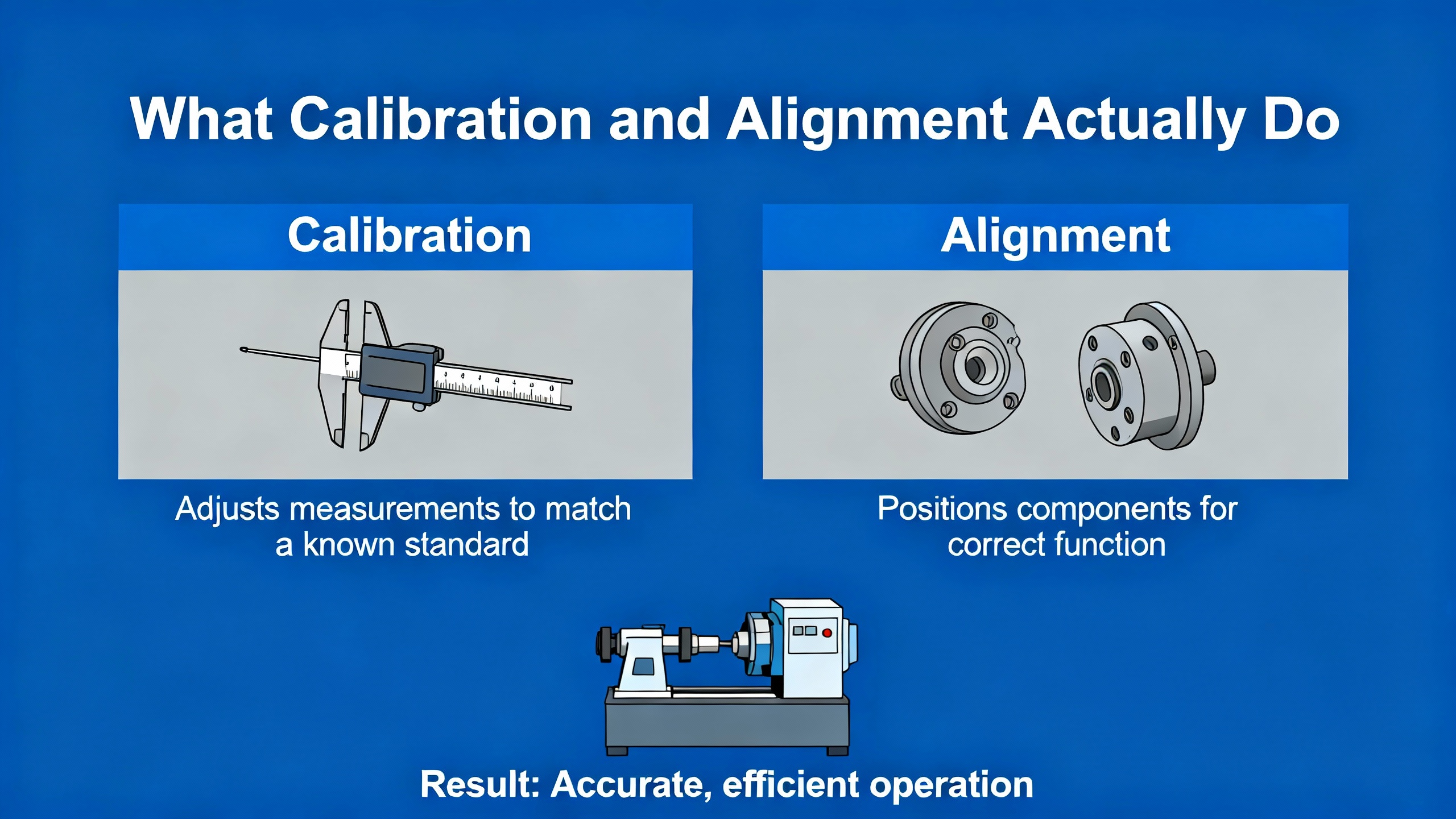
What Calibration and Alignment Actually Do
In the field, people often use “calibration” and “alignment” as if they were the same thing. They are tightly linked, but they solve different parts of the problem.
Mechanical alignment is the physical side. It ensures the encoder’s sensing element is in the right place and orientation relative to the shaft or scale it is measuring. In rotary encoders, that means concentricity, minimal runout, proper air gap to a magnetic or capacitive ring, and a rigid mount that does not flex. Heavy‑duty encoder manufacturers working in steel plants and offshore rigs have repeatedly shown that shaft misalignment and bearing overload are major contributors to disc damage, unstable signals, and premature failure.
Calibration is the electrical and mathematical side. Sensor calibration specialists emphasize that any sensor, including encoders, drifts over time due to aging, temperature, and mechanical changes, and that calibration aligns the sensor’s output with a trusted reference. In absolute motor encoders such as integrated units used on servo drives, calibration maps the relationship between raw sensor signals and the true mechanical angle, and determines the correct commutation offset so torque control operates with the rotor and stator fields properly aligned. Documentation from integrated encoder platforms like Circulo explains that a poor calibration can give you a wrong absolute angle at startup, which in turn destabilizes torque control and misreports position.
There is a close parallel with the way analog‑to‑digital converters are calibrated. High‑precision ADC design notes describe offset, gain, and linearity errors and how digital calibration measures those errors against a reference and corrects them in software. Modern encoder calibrations do something similar: they rotate the motor or axis through known positions, measure the deviations between expected and measured values, and then apply digital corrections so that the encoder’s reported position matches the true mechanical position as closely as possible.
The key takeaway is that mechanical alignment reduces how much error you have in the first place, while calibration compensates for the remaining systematic error. If either is ignored, encoder feedback errors are almost guaranteed to show up later in the life of the machine.
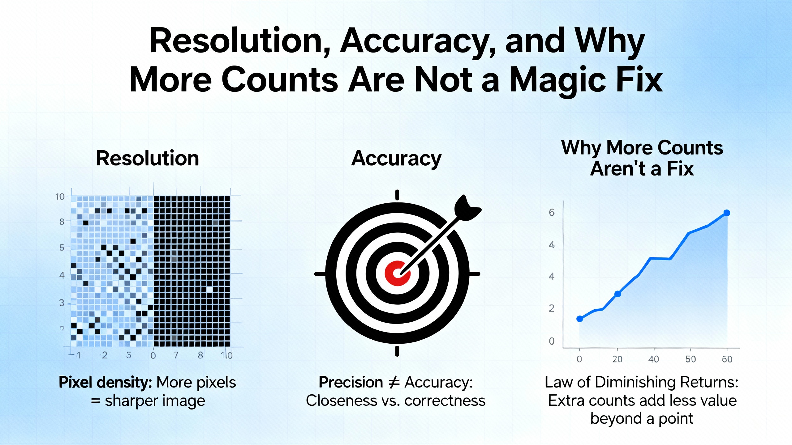
Resolution, Accuracy, and Why More Counts Are Not a Magic Fix
When a feedback problem appears, the first instinct is often to reach for a higher‑resolution encoder. Application notes from encoder suppliers are clear, however, that resolution and accuracy are not the same thing.
Encoder resolution tells you how finely the encoder divides motion, typically in pulses per revolution for incremental devices or bits for absolute devices. It defines the smallest change in position the encoder can report. Manufacturers routinely offer rotary encoders with ten thousand pulses per revolution and more, and interpolation can multiply that further.
Accuracy, on the other hand, is the difference between what the encoder reports and the true mechanical position. Technical notes on encoder resolution and accuracy show that two encoders can have the same resolution yet very different accuracy, because of manufacturing imperfections and mechanical installation issues. Moreover, system‑level accuracy is often limited by the mechanics: backlash in gearboxes, play in ball screws, and misalignment between the encoder and the driven axis. The encoder faithfully reports what it sees, but if it is bolted to a mounting surface that wobbles, or a scale that is tilted, its readings will be wrong.
A detailed study on rotary encoder “scale swash” from a major metrology company illustrates this. When the graduated scale on a rotary encoder is slightly tilted relative to the true axis of rotation, the scale’s periphery moves axially once per revolution and the graduations yaw back and forth. In a practical example with a roughly 8 in diameter scale and a small tilt, that combination of axial motion and yaw produces a sinusoidal position error once per revolution and a smaller twice‑per‑revolution error. The conclusion in that work is simple and blunt: install the scale carefully to minimize swash and place the readhead where concentricity was set, or you bake a periodic error into the system that no amount of resolution can remove.
For linear encoders, guidance from motion‑control specialists makes the same point in a different way. Magnetic or steel‑tape encoders may show only a small linearity error over a travel of around 1.6 ft, but their total absolute error across that span can be significantly larger. The slope‑type error can often be corrected electronically, yet subdivisional error within one signal period still creates small cyclic position or velocity ripple at low speeds. Glass scales offer tighter accuracy specs, but they do not excuse poor mechanical alignment.
In other words, chasing more counts without addressing alignment, calibration, and mechanics is an expensive way to keep the same core problem.
Incremental, Absolute, and Resolver Feedback in Practice
Not every feedback device behaves the same way when power is cycled, when calibration is run, or when mechanical alignment drifts. Understanding the basic categories helps you choose the right strategy for fixing feedback errors.
Incremental encoders report relative motion. A common example is a quadrature encoder with A and B channels and an optional index pulse once per revolution. As discussed in servo drive forums, these encoders do not inherently know the absolute rotor angle at power‑up. For drives using field‑oriented control, the controller must know the rotor’s electrical position to align the stator field correctly. Without that information, closed‑loop control with high current becomes unsafe. Some systems handle this by performing an encoder offset calibration at startup that deliberately moves the motor to find the electrical angle. If mechanical constraints prevent any motion at startup, this approach is problematic. Designers of high‑current servo drives explicitly warn against bypassing the calibration logic with configuration flags, because entering closed‑loop control with an uncalibrated incremental encoder is unsafe by design.
Absolute encoders report a unique code for each mechanical position. Integrated encoders such as those used on servo kits or high‑end actuators compute a true absolute angle at startup from magnetic or optical patterns and store calibration data in internal memory. Documentation for these devices explains that after installation or any mechanical change, a dedicated calibration procedure must be run. The calibration data is then used by the firmware at every startup so the absolute angle and commutation offset are correct from the moment the drive wakes up. Some vendors define a “phase reserve” metric derived from the phase error curve; they require phase reserve above a certain percentage, otherwise the encoder cannot reliably provide an absolute angle.
Resolvers and resolver‑based “smart sensors” occupy a middle ground. CNC maintenance guides compare encoders and resolvers by noting that resolvers tend to have lower resolution but far higher durability and environmental resistance. That makes them attractive in harsh environments where shock, vibration, and high temperatures are the norm. The trade‑off is that resolver decoding electronics must be more complex, and system resolution is lower unless interpolation is used.
Capacitive absolute encoders such as Netzer’s Electric Encoder technology bring another perspective. Their documentation describes a holistic sensor: a dielectric rotor with fine and coarse sinusoidal patterns interacting with a modulated electric field, producing sine and cosine outputs that represent absolute position. The system integrates signals over the entire rotor area, making it tolerant to mechanical misalignment, vibration, and contaminants. These encoders are designed to be calibrated once, with a short motion and either a push‑button or application software. After this one‑time calibration, they provide absolute position immediately at power‑up and are inherently immune to magnetic fields and highly resistant to electrical noise.
The practical implication is that the calibration and alignment strategy must be matched to the feedback type. Incremental encoders demand careful handling of homing, index pulses, and startup calibration routines. Absolute encoders and resolvers shift more of the burden to the initial calibration and mechanical alignment but reward you with known position at wake‑up.
Here is a concise comparison to keep that picture clear:
| Feedback type | What it provides at power‑up | Calibration and alignment implications | Typical strengths for feedback error resilience | Typical trade‑offs |
|---|---|---|---|---|
| Incremental encoder | No absolute position, only motion and direction | Requires homing routine or offset calibration, sensitive to index handling | High resolution, simple signals, widely supported | Needs motion at startup, vulnerable to wiring noise and missed counts |
| Absolute optical/magnetic | Unique code per position, true absolute angle | One‑time or occasional calibration, mechanical alignment critical | Immediate position on wake‑up, good for safety and torque control | More complex, often higher cost, sometimes less tolerant of contamination |
| Resolver | Analog sine/cosine position signals | Requires excitation and decoder calibration, mechanically robust | Survives harsh environments, high shock and temperature | Lower resolution, more complex electronics |
| Capacitive “holistic” type | Absolute sine/cosine outputs from full‑area rotor sensing | Short one‑time calibration, tolerant of moderate mechanical imperfections | Immune to magnetic fields, strong EMI resistance, low wear | Requires vendor software or tools, not as widely used as optical incremental |
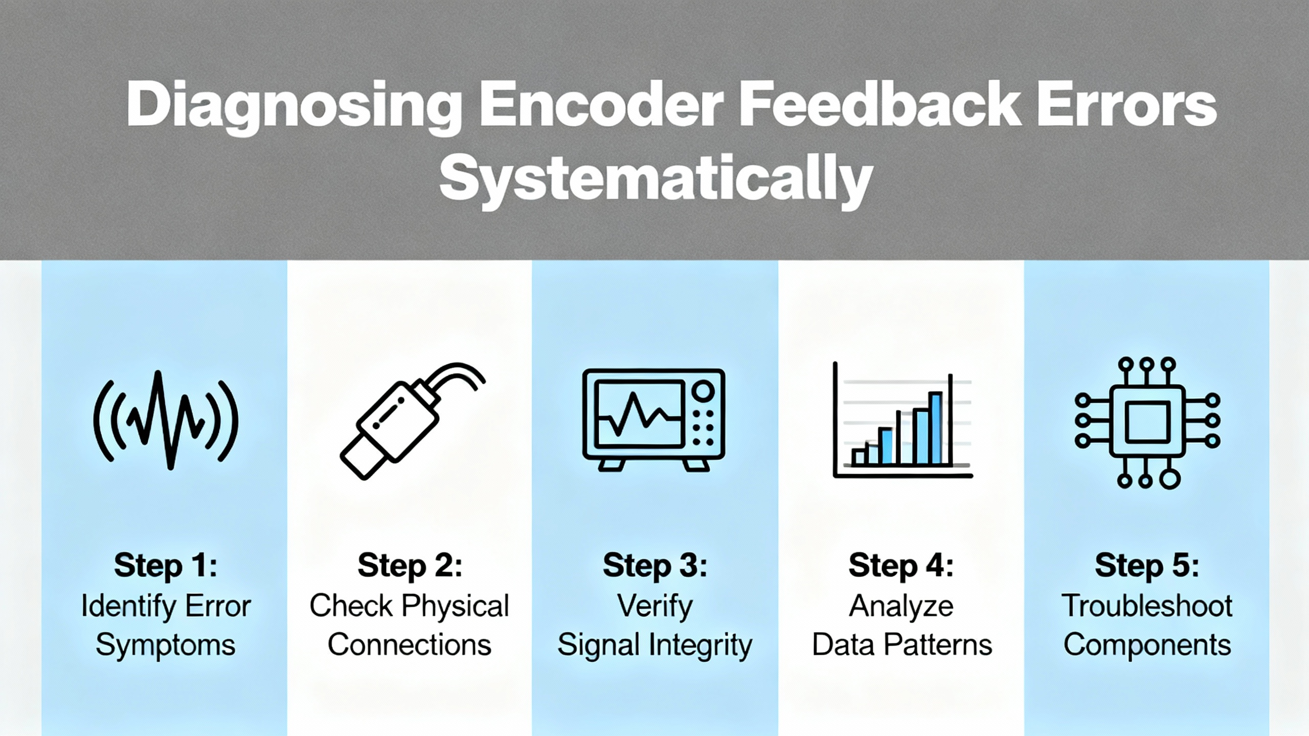
Diagnosing Encoder Feedback Errors Systematically
When a drive throws an encoder feedback fault or the machine clearly does not move as commanded, a structured diagnostic process saves a lot of guesswork. Field experience and repair guides point to three broad layers to investigate: symptoms, mechanical installation, and electrical integrity, followed by instrument‑based verification and calibration.
Begin by clarifying the symptom in the context of the control mode. In current or torque control, incorrect feedback typically shows up as poor torque production, cogging, or a drive that refuses to enter closed loop because it cannot trust the encoder. In velocity and position modes, you may see drifting position, unstable speed, or limit switches tripping when the controller believes the axis is somewhere else. Servo motor encoder troubleshooting articles emphasize that abnormalities can appear even under no‑load conditions, for example as jittering position readings or fault codes about feedback mismatch.
Next, look at the mechanical installation with the same suspicion you would apply to a misaligned gearbox. Heavy‑duty encoder suppliers who work in steel plants and offshore applications list shaft misalignment, bearing wear, and excessive vibration as a major cause of intermittent or unstable signals. If the encoder is coupled directly to the motor shaft, check for side load, bent shafts, or rigid couplings that transfer misalignment into the encoder bearings. For integrated encoders with magnetic rings or discs, the calibration and diagnostic tools provided by the manufacturer are invaluable: graphics of phase error curves, phase reserve percentages, and ring distance maps will often reveal whether the ring is too close, too far, or not concentric. Documentation for integrated systems notes that rings placed too close to the sensor chip show regular, high‑amplitude oscillations in the phase error curve, while rings placed too far produce more irregular oscillations and outliers.
Electrical integrity cannot be an afterthought. Articles on common encoder failures in heavy industry describe repeated real‑world cases where unshielded encoder wiring was run alongside high‑power motor cables. The result was drifting feedback, frequent errors, and ultimately a plant engineer who finally found that rerouting and shielding the encoder cables restored reliability. Industrial troubleshooting guides add that poor grounding, shared power lines between drives and encoders, and inadequate surge protection can inject destructive voltage spikes into the encoder electronics. Before digging deep into calibration, it is worth inspecting the cable routing, connector tightness, shield terminations, and separation between signal and power wiring.
At this point, instruments become your best allies. A digital multimeter can confirm basic supply voltage and wiring continuity, but it is essentially blind to what matters most: the time‑varying shape of the encoder signal. Measurement specialists emphasize that oscilloscopes are the correct tool for observing encoder waveforms. Field guides to diagnosing conveyor encoders, for example, describe a practical approach: hook the oscilloscope to channels A and B, choose a time base that shows several pulses, and adjust the voltage scale so that the high and low levels are clear. This allows you to verify duty cycle, phase relationship between channels, signal amplitude, and the presence of noise spikes or ringing. Problems such as high‑frequency noise from poor shielding, missing pulses, and skew between A and B become immediately obvious when viewed on a scope.
Diagnostic recommendations from encoder manufacturers echo this. They suggest confirming that A and B are in quadrature with the expected ninety‑degree phase shift, that any index pulse is present and clean, and that the signal swings reach the specified logic levels. For encoders with sine and cosine outputs, monitoring the analog waveforms can reveal unequal amplitudes or distortion that point to mechanical or internal sensor issues.
Only when mechanical, electrical, and basic signal integrity checks are complete does it make sense to move into full calibration.
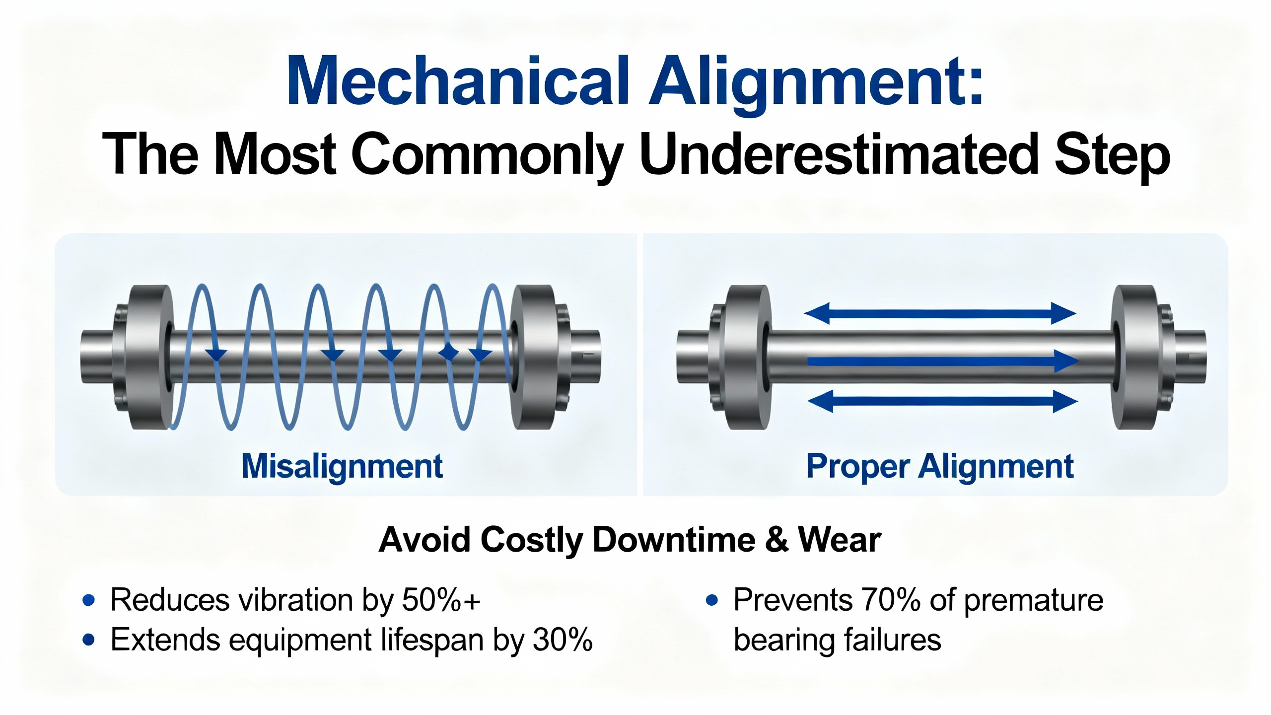
Mechanical Alignment: The Most Commonly Underestimated Step
In more than two decades of commissioning drives and motion systems, I have found that most “mysterious” encoder feedback errors eventually trace back to mechanical alignment. The encoder may be well‑specified and carefully calibrated, but if it is bolted to a warped bracket or a loose shaft, it is doomed from the start.
For rotary encoders mounted with couplings, inspect the coupling type and installation. Flexible couplings should be used to absorb minor misalignment rather than to force the encoder bearings to carry it. Industrial encoder suppliers warn that excessive misalignment or side load accelerates bearing wear, leading to vibration, noise, and erratic signals. If the encoder is integrated into a motor, as with motor‑side encoders in compact actuators, improper mounting of the motor itself or uneven torque on mounting bolts can induce tilt or eccentricity that the encoder will faithfully measure.
For ring‑type encoders, mechanical diagnostics from integrated encoder vendors are very instructive. They provide tools that build a distance map around one revolution, highlighting axial runout or eccentric mounting. If you see a pronounced once‑per‑revolution deviation, that is a strong indicator of a tilted or off‑center magnetic ring. Setup guidance also stresses the importance of keeping the ring’s air gap within specification. If the ring is too close, fields saturate and the phase error curve shows regular, high peaks. If it is too far, signal amplitude drops and irregular peaks appear. Both conditions undermine calibration and absolute angle reliability.
The earlier discussion on scale swash in precision rotary encoders reinforces this picture in a more quantitative way. A slightly tilted scale introduces a sinusoidal axial motion and yaw that ultimately manifests as once‑per‑revolution and twice‑per‑revolution position errors. In many industrial axes, that will show up as a subtle but repeating position error at one or two distinct angular frequencies. The conclusion is straightforward: take time to dial in mechanical flatness and concentricity before trusting any calibration routine.
Finally, remember that calibration itself can shift the reported absolute angle. Integrated encoder notes explain that a recalibration can change the absolute angle by around 11 degrees in some systems. If you have taught homing positions, hard stops, or reference marks before a recalibration, you must redo those procedures afterward. Treat encoder calibration as a mechanical reference change and update the rest of the system accordingly.
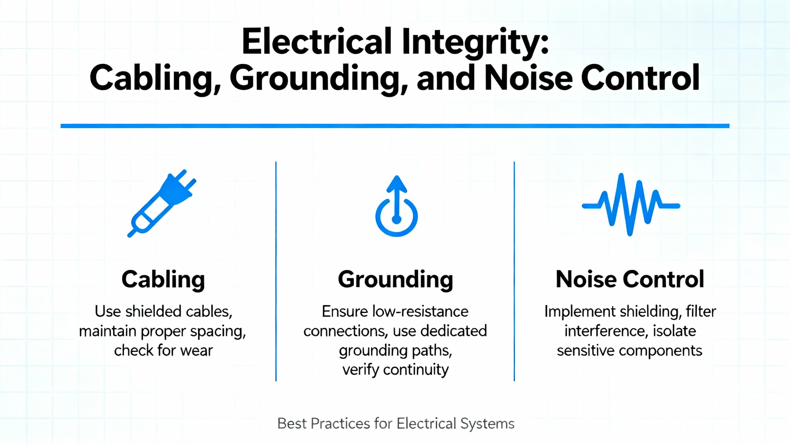
Electrical Integrity: Cabling, Grounding, and Noise Control
Once the mechanical side is under control, electrical integrity becomes the next limiting factor. Encoders live in the same cabinets as drives, contactors, and power supplies, and in the same conduits as motor leads and high‑current buswork. Without disciplined wiring, feedback errors become inevitable.
Manufacturers that support heavy‑duty applications emphasize several consistent practices. Encoder cables should be shielded and routed separately from high‑voltage or high‑current motor cables. Grounding must be done deliberately: shields terminated to the correct reference point, no random pigtails, and no shared grounds that invite ground loops. Surge protection helps protect the encoder electronics from voltage spikes, particularly in environments with long cable runs or frequent switching.
Signal format matters as well. Encoder signal application notes explain that differential line‑driver outputs are more robust in noisy environments than single‑ended TTL or HTL. With a differential signal pair, noise coupled onto both lines tends to be rejected by the receiver, allowing longer cable runs and better immunity to electromagnetic interference. That said, even differential lines will struggle if the cable is unshielded and runs alongside motor leads for long distances.
Interestingly, not all encoder technologies are equally sensitive to electromagnetic noise. Netzer’s Electric Encoder documentation notes that their capacitive encoders are inherently immune to magnetic fields and are internally shielded against electric fields, with field‑proven performance in demanding defense applications. That does not remove the need for correct grounding and cabling, but it can make a dramatic difference in environments where traditional magnetic or optical encoders struggle.
Systematic troubleshooting guidance from encoder repair sources suggests starting with simple checks: verify that the encoder receives the correct supply voltage, that there are no broken wires or loose connectors, and that cable jackets and strain reliefs are intact. Signal interruptions, intermittent outputs, and skipped counts often trace back to cracked connectors or cables damaged by repeated flexing or vibration. In severe cases, power‑supply instability can produce erratic behavior that mimics encoder failure; verifying voltage stability under load with a meter or scope is therefore a necessary step.
Calibration Fundamentals for Encoders
Once you trust that the mechanical and electrical foundations are sound, calibration is where you close the loop between sensor and reality.
Calibration best practices from sensor repair experts apply directly to encoders. Before touching parameters, you should confirm whether adjustment is actually needed by running a benchmark test. That might be a simple move to a known mechanical reference, a comparison against a reference encoder mounted in tandem, or a measurement against a high‑precision linear or rotary standard. All calibration should be done in a controlled environment as much as the plant allows, since temperature and humidity can influence results.
Proper tools matter. A reference standard, whether an external encoder, resolver, or mechanical gauge, is your yardstick. For integrated encoder systems, vendor‑supplied software or wizards orchestrate the calibration routine, commanding slow revolutions and capturing raw sensor data. For example, Circulo integrated encoders use repeated slow revolutions at specified speeds and travel ranges, then evaluate phase error and phase reserve to judge calibration quality. If the phase reserve falls below required thresholds, the encoder is considered unreliable as an absolute device.
Advanced practice aligns closely with ADC calibration techniques. In ADCs, digital correction maps offset, gain, and linearity errors using measurements at known points, often stored as lookup tables or coefficients. Encoder calibration can follow a similar pattern. Some manufacturers implement tables that map each raw count or segment of the revolution to a corrected value, reducing systematic angular error. Others adjust commutation offset and gain values so that the field‑oriented control unit sees the correct electrical angle at all times. These routines may run once during commissioning, or periodically in the background if the firmware supports self‑calibration.
One crucial rule that arises again and again in servo drive and encoder documentation is that configuration flags for “pre‑calibrated” encoders are not shortcuts. In high‑current drives, designers enforce flags such as “pre‑calibrated” and “is ready” so that users cannot accidentally enter closed‑loop control with uncalibrated feedback. Attempting to bypass those protections to avoid a startup calibration, particularly with incremental encoders that have no index, is considered unsafe.
Finally, complete the calibration by validating it. After a calibration, drive the axis through a full cycle that represents real operation. Compare commanded and measured positions or speeds, and watch for oscillations, overshoot, or residual periodic errors. If the encoder is used for commutation, verify that torque production is smooth and that the drive enters and exits closed loop without hesitation.
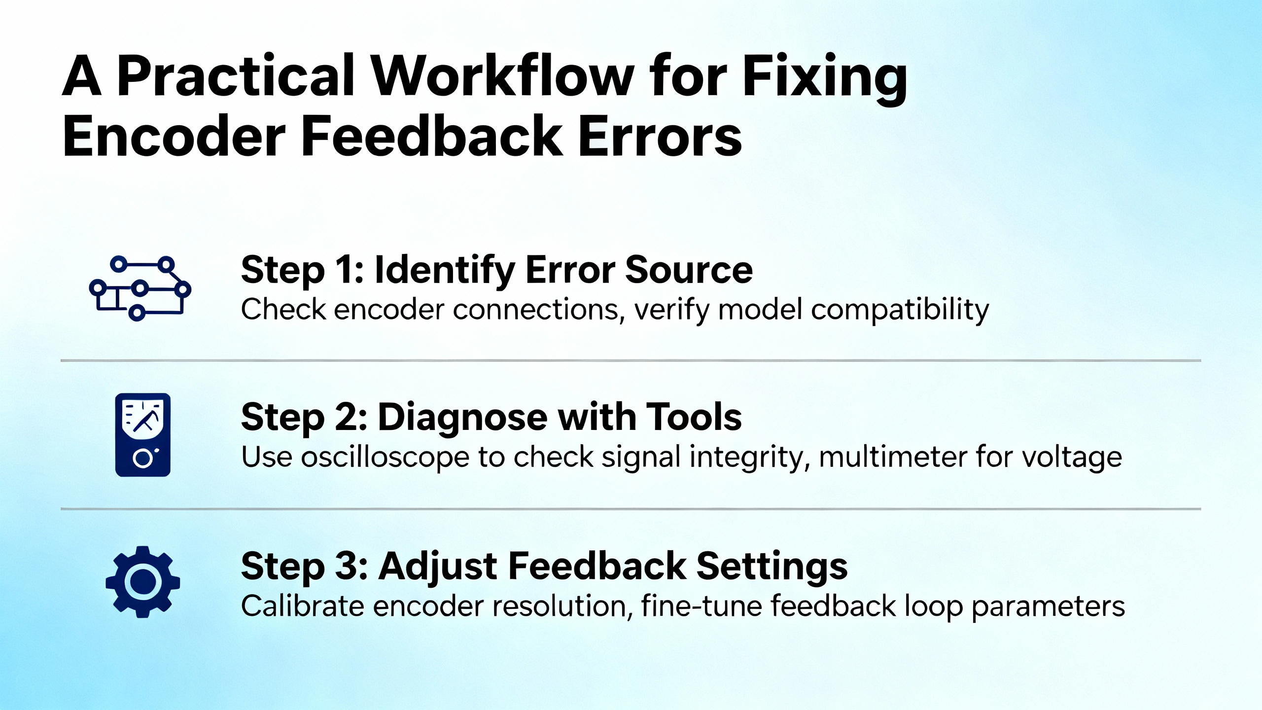
A Practical Workflow for Fixing Encoder Feedback Errors
When you are standing in front of a down machine, theory is helpful only if it translates into a reproducible process. The most effective workflow I have used, which aligns well with guidance from encoder repair and oscilloscope application notes, follows a clear sequence.
Start by stabilizing the situation and making it safe. Power down, lock out as required, and ensure mechanical motion is controlled. Encoder repair guides stress basic safety: never open or adjust encoders with power applied to the motor, and always follow the equipment manufacturer’s safety procedures.
Then clarify the failure mode with the least invasive tests. Use the drive’s diagnostic pages or PLC status to read current encoder counts, velocities, and alarm codes. Manually rotate the shaft (if safe) and confirm that counts change smoothly and in the correct direction. If the feedback appears to freeze or jump, you already know something is fundamentally wrong.
Move on to mechanical inspection. Check mounting bolts, couplings, brackets, and, for ring encoders, the ring’s seating and distance to the sensor. Look for visible contamination such as oil, fine metal particles, or dust, especially in environments like steel mills where disc contamination has been identified as a leading cause of encoder failure. Rotate the shaft and feel for roughness or binding that suggests bearing damage.
Electrical inspection follows. Verify power at the encoder connector with a meter, check continuity on each signal line, and visually inspect the cable route. Look for unshielded runs laid directly alongside motor cables or through areas of strong electromagnetic interference. If the encoder is far from the drive, consider whether the cable length is within what the manufacturer recommends.
At this point, instrumented testing with an oscilloscope can distinguish between logic‑level issues and more subtle analog problems. Attach probes to channels A and B and, where available, the index. Set the timebase to show several periods and adjust the vertical scale so pulses are clearly visible. Check whether the duty cycle is approximately balanced, whether the phase difference between A and B is consistent, and whether the index pulse appears once per revolution and with the correct width. Measure high and low voltage levels to ensure they fall within specification and look for noise spikes, ringing, or irregular pulse spacing. Oscilloscope‑based case studies on conveyor systems show that issues such as damaged cable shielding and worn encoders manifest as high‑frequency noise and irregular pulse intervals that are difficult or impossible to spot with a meter alone.
If the mechanics and signals pass these checks, perform the appropriate calibration procedure for your encoder type. For incremental encoders that require offset calibration, follow the drive’s documented routine, which usually commands slow revolutions and measures electrical angle alignment. For integrated absolute encoders, use the vendor’s software or wizard, ensuring that the axis can move smoothly through the required range. Keep in mind the guidance from integrated encoder documentation: if power or communication is interrupted during calibration, internal nonvolatile memory may be left in an invalid state, and the procedure must be repeated from the beginning.
Finally, validate under real operating conditions. Run the machine through its typical cycle, watching not just for the absence of alarms but for correct positioning, smooth torque, and stable speed. Pay attention to any residual once‑per‑revolution or twice‑per‑revolution errors, which may point back to subtle mechanical misalignment such as scale swash or ring eccentricity. Document the final calibration values, date, tools used, and any deviations you observed, in line with best practices from sensor calibration management. That record will be invaluable the next time the line stops at two in the morning.
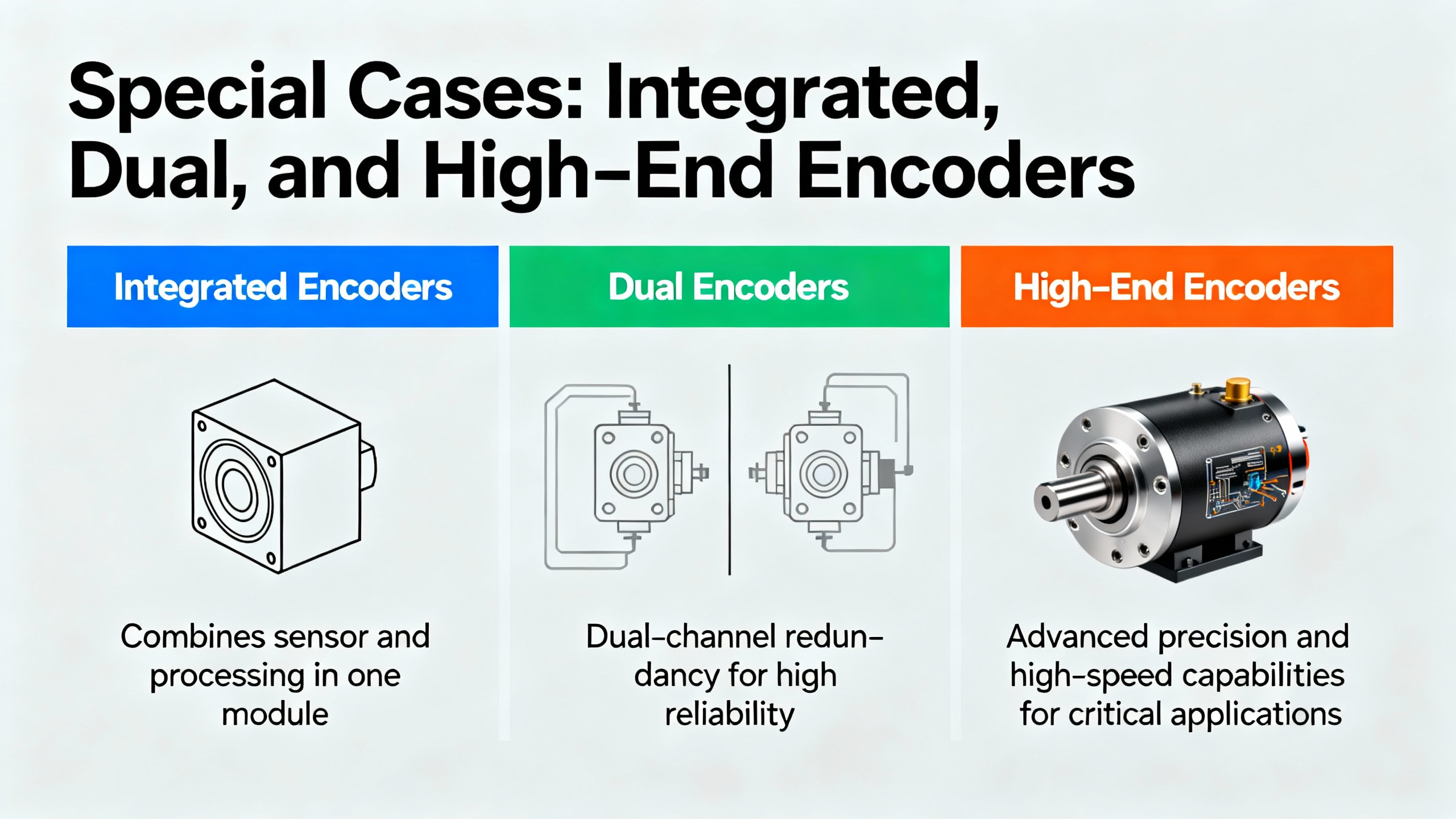
Special Cases: Integrated, Dual, and High‑End Encoders
Some encoders embed more intelligence and complexity than a simple disc and sensor. Integrated dual encoders, high‑resolution absolute sensors used for commutation and position simultaneously, and space‑rated capacitive encoders all bring additional considerations.
In dual‑encoder systems where one encoder sits on the motor shaft and another on the gearbox or output shaft, the motor‑side encoder must be calibrated first. Circulo’s calibration procedure is explicit about this: the inner motor‑shaft encoder is calibrated, then the outer gearbox or output‑shaft encoder. During calibration, the firmware may also perform an automatic commutation offset detection if the calibrated encoder is used for commutation. If that automatic step fails, a separate commutation offset detection with production firmware is required. Only after this chain of calibration and offset detection can the axis be tuned reliably in velocity or position control.
Integrated encoders that include health monitoring after calibration are increasingly common. Recent firmware releases for some drives add periodic checks of raw encoder signals, distance maps, and ring alignment, raising errors if mechanical shifts or magnetic ring damage are detected. This kind of built‑in surveillance helps catch gradual drifts that would otherwise show up as sporadic feedback errors months after a mechanical bump or thermal event.
High‑end capacitive encoders such as those used in aerospace applications add yet another dimension. Documentation for space‑grade encoders from Netzer, for example, describes encoders designed to withstand extreme temperatures from roughly −67°F to about 257°F, with brief tolerance up to around 302°F, as well as radiation and single‑event effects in low or medium Earth orbit. These devices are typically maintenance‑free with mean time between failures measured in decades, but they still require a correct one‑time calibration and proper installation. In high‑stakes systems like these, vendors often offer batch testing of identical models before final deployment, underscoring the importance of calibration integrity.
In all of these special cases, the common thread is that calibration, once performed correctly on a mechanically sound installation, provides a long‑term foundation for accurate feedback. Skipping or rushing that step undermines the very advantages these advanced encoders offer.
When to Rethink the Feedback Architecture
There are situations where no amount of careful alignment and calibration can deliver the behavior you need, simply because the feedback architecture itself is mismatched to the application.
A good example appears in discussions of field‑oriented drives using high‑resolution incremental encoders without an index. In these systems, the drive must move the motor during startup to determine the electrical offset. If the mechanical system cannot tolerate this motion, for example in a loaded vehicle or a machine holding a delicate workpiece, you can never safely get a reliable commutation angle from that incremental encoder alone. Developers of these drives recommend switching to an absolute encoder, or at least an incremental encoder with an index pulse that can be searched with minimal movement after power‑up.
Similarly, CNC maintenance resources that compare encoders and resolvers point out that resolvers, while lower in resolution, offer higher durability and environmental resistance. In extremely harsh environments with continual vibration, shock, and contamination, replacing a fragile high‑resolution optical encoder with a resolver and appropriate decoding electronics may be more effective than repeatedly repairing encoders.
In linear motion systems, the choice between linear encoders mounted directly on the load versus rotary encoders on the motor or screw is another architectural decision. Notes on linear encoder accuracy highlight that linear encoders can relax drivetrain precision requirements but also introduce their own error sources, such as linearity and subdivisional error. The encoder only measures position where it is mounted; if you place it on the motor rather than the load, mechanical backlash and compliance between the two will never be visible in the feedback.
If you find yourself continually fighting feedback errors in a particular axis despite careful calibration and alignment, it is worth stepping back and asking whether the encoder type, mounting location, and feedback architecture are fundamentally aligned with the performance and environmental demands of the application.

FAQ
How often should I recalibrate my encoders?
Calibration frequency depends on how quickly your system drifts, which is driven by mechanical wear, temperature cycles, and environmental exposure. Sensor calibration guidance recommends starting with a defined schedule that reflects process criticality and environmental severity, then adjusting based on actual drift data. Integrated encoders that support health monitoring and phase reserve measurements can signal when mechanical or magnetic conditions have changed enough to warrant recalibration. Any mechanical change in the encoder stack, such as replacing a coupling, remounting a motor, or changing a gearbox, is a clear trigger to recalibrate, and integrated encoder documentation explicitly states that homing and reference alignment should be repeated after calibration because the reported absolute angle can shift by several degrees.
Can software alone fix encoder feedback errors?
Digital calibration and error compensation are powerful tools, but they cannot rescue a fundamentally bad installation. ADC calibration literature shows that software correction can remove systematic offset, gain, and linearity errors if the underlying hardware is stable and repeatable. Encoder calibration works the same way: it can map and reduce systematic angular errors, but it cannot eliminate backlash, mechanical wobble, or a magnetic ring that physically moves with temperature. Experience from encoder manufacturers and repair specialists consistently shows that unresolved mechanical misalignment, contamination, and wiring or grounding issues will continue to produce intermittent or environment‑dependent faults no matter how sophisticated the calibration algorithm is. Software is most effective when it is the last layer on top of sound mechanics and clean signals.
Why do encoder errors appear only at certain speeds or under load?
Several documented error sources only become visible under specific operating conditions. Subdivisional error in linear encoders, for example, shows up as cyclic velocity ripple at low scanning speeds, even if the position error over a full travel is small. Vibration‑induced issues often appear at particular speeds where structural resonances are excited. Troubleshooting guides for rotary encoders also note that cables or connectors that seem fine at rest can exhibit intermittent opens or changing impedance when flexed under motion, leading to skipped counts or noise. Under load, mechanical structures deflect, couplings twist, and shafts bend slightly; if the encoder is mounted in a way that amplifies those effects, the resulting position error will be load‑dependent. That is why validation under real operating conditions is a mandatory part of any calibration process.
Closing
Encoder feedback errors are rarely the fault of a single bad component. In most plants I have worked in, they are the product of a chain: a rushed mechanical mount, a cable routed “just for now,” a skipped calibration, and then months of incremental drift. The good news is that the same chain can be rebuilt in the other direction. If you start with solid mechanics, enforce clean electrical practices, and treat calibration as a disciplined, documented process rather than a button to click, encoders become what they should be: invisible, boring, and utterly reliable partners in your control system.

References
- https://blender.cs.illinois.edu/paper/caliboration1.pdf
- https://www.plctalk.net/forums/threads/encoder-woes.97060/
- https://www.potensielevator.com/how-to-determine-that-your-elevator-encoder-is-malfunctioning.html
- https://www.yumoelectric.com/Troubleshooting-Guide-for-Rotary-Encoder-Problems-id63015927.html
- https://www.encoderhohner.com/hohner-technical-tips-common-encoder-failures-and-how-to-prevent-them-%F0%9F%93%8C/
- https://euro-hubner.nl/common-encoder-failures-and-how-to-prevent-them/
- https://gesrepair.com/best-practices-for-calibrating-your-manufacturing-sensors/
- https://hackaday.io/page/21749-how-to-solve-an-encoder-error-in-a-servo-motor
- https://lorentzzi.com/encoder-problems-with-solutions-the-ultimate-guide/
- https://netzerprecision.com/faq/
Keep your system in play!
Top Media Coverage
Categories


Related articles Browse All
-
 amikong NewsSchneider Electric HMIGTO5310: A Powerful Touchscreen Panel for Industrial Automation2025-08-11 16:24:25Overview of the Schneider Electric HMIGTO5310 The Schneider Electric HMIGTO5310 is a high-performance Magelis GTO touchscreen panel designed for industrial automation and infrastructure applications. With a 10.4" TFT LCD display and 640 x 480 VGA resolution, this HMI delivers crisp, clear visu...
 -
 BlogImplementing Vision Systems for Industrial Robots: Enhancing Precision and Automation2025-08-12 11:26:54Industrial robots gain powerful new abilities through vision systems. These systems give robots the sense of sight, so they can understand and react to what is around them. So, robots can perform complex tasks with greater accuracy and flexibility. Automation in manufacturing reaches a new level of ...
 -
 BlogOptimizing PM Schedules Data-Driven Approaches to Preventative Maintenance2025-08-21 18:08:33Moving away from fixed maintenance schedules is a significant operational shift. Companies now use data to guide their maintenance efforts. This change leads to greater efficiency and equipment reliability. The goal is to perform the right task at the right time, based on real information, not just ...


- Q&A
- Policies How to order Part status information Shipping Method Return Policy Warranty Policy Payment Terms
- Asset Recovery
- We Buy Your Equipment. Industry Cases Amikong News Technical Resources Why choose us
- Registered Address
-
32D Guomao Building, No.388, Hubin south Road, Siming district, Xiamen,Fujian, China

Leave Your Comment