
-
Please try to be as accurate as possible with your search.
-
We can quote you on 1000s of specialist parts, even if they are not listed on our website.
-
We can't find any results for “”.
Level Sensor Fault Diagnosis: Common Problems and Solutions
In every serious process plant I have worked on, level is one of the “make-or-break” measurements. Get it wrong and you are looking at foaming tanks, cavitating pumps, overflows, environmental incidents, and long nights in the control room. The irony is that many “bad” level sensors are not bad at all. They are victims of poor installation, mismatched technology, or process conditions that were never considered during design.
This article walks through level sensor fault diagnosis the way a veteran systems integrator approaches it: start with the process, use a structured troubleshooting method, and only blame the instrument after you have ruled out the basics. Along the way, I will reference practical guidance from field-instrument manufacturers, technical bulletins, and troubleshooting guides from industry sources, and translate that into shop-floor tactics you can apply on your own systems.
How Level Sensors Really Work In The Field
A level transmitter measures the level of a liquid or solid in a vessel and converts that into a proportional signal, typically a 4–20 mA loop or a digital value into a PLC or DCS. In process industries such as oil and gas, chemicals, power, and cement, level instruments are everywhere: storage tanks, sumps, day tanks, reactors, and CIP skids.
From an engineering standpoint there are two main ways to classify level devices.
First, by measurement method. Direct devices show you the level itself: a sight glass, a float gauge with a mechanical pointer, or a magnetic gauge that gives a visual column. Indirect devices infer level from another quantity such as pressure, capacitance, or time-of-flight. Most modern transmitters are indirect.
Second, by working principle. In common plant instrumentation you will encounter capacitance, hydrostatic (pressure-based), magnetic float, radar, ultrasonic, guided microwave, and simpler discrete level switches. Electronic devices give you remote indication and automatic control; mechanical ones are simpler but local only.
Understanding the principle is not academic. A radar sensor that relies on microwave reflections will handle foam differently from an ultrasonic sensor that relies on sound waves. A capacitance probe will respond to changes in fluid conductivity that a simple float will ignore. When you see a bad reading, the physics tells you where to look first.
Faults, Symptoms, And Root Causes: Getting The Vocabulary Right
In fault-diagnosis literature for process plants, a “fault” is any deviation from desired behavior, not just a complete failure. A level loop that drifts a few inches high and slowly wastes product is just as much a fault as a dead transmitter. A “symptom” is what you observe: the HMI shows a stuck value, the trend is noisy, the pump trips on low level even though the tank looks full through the sight glass.
A “root cause” fault is the underlying problem that generates those symptoms. For level, root causes might include a scarred radar antenna, a loose 4–20 mA loop connection, incorrect range configuration, foam on the liquid surface, or a process fluid that changed to a more viscous or corrosive product without updating the instrument specification.
Fault detection is recognizing that something is wrong at all. Fault diagnosis or isolation is figuring out which component and what cause, to the point where you can take a specific corrective action. Most plants blur the terms and just talk about “troubleshooting,” but in practice the distinction matters. You can only fix what you have properly isolated.
One more subtlety that experienced engineers emphasize, and that is clear in both academic and industrial fault-management work, is the difference between sensor faults and process faults. A sensor fault means the instrument is no longer measuring correctly. A process fault means the instrument is telling the truth about an abnormal process condition. Mistaking one for the other leads to a lot of unnecessary transmitter replacements and very few real fixes.
Start With The Process, Not The Transmitter
When someone calls saying “the level transmitter is bad,” my first reaction is to ask questions about the tank and the process, not the instrument model number. A pressure-based level question on a technical forum illustrates why: an experienced responder refused to guess at the problem until they knew basic facts such as tank size, shape, orientation, liquid type, temperature, and whether vapors were present. Without that information, you are troubleshooting blind.
Tank geometry matters. A tall, narrow vertical tank behaves very differently from a wide horizontal one. Internal structures such as baffles, ladders, and agitators create reflections for radar and ultrasonic sensors and can disturb the field around guided microwave probes. The shape also affects hydrostatic relationships and where you can practically mount a sensor.
Fluid properties matter just as much. The type of liquid, whether it is corrosive, viscous, or abrasive, and whether it tends to foam or form vapors will all influence sensor choice and behavior. Editorial and application notes on liquid-level sensors repeatedly highlight issues with corrosion, viscosity, foam, and vapor layers. Vendors respond with corrosion-resistant materials such as stainless steel, PVC, PP, PVDF, PTFE, or PEEK, and with special signal processing for foam and vapors.
Operating conditions are the third leg of the stool. Temperature swings, pressure changes, humidity, and contaminants can all distort readings. Studies on field instrument failures show that temperature extremes and environmental stress cause signal distortion, drift, and premature failure if not managed. Power supply stability is another recurring theme: radar-level application notes mention unstable operation when the working voltage is outside specification.
Before touching the transmitter, I apply a structured troubleshooting method similar to the Navy six-step procedure that industrial guides recommend for critical automation equipment. Recognize the symptom clearly, elaborate it by running an operating cycle or reviewing trends, list possible faulty functions, localize to a function (sensor, wiring, process interface, control logic), localize to a specific component, then do failure analysis and record what happened. That structure keeps you from jumping straight to “swap the transmitter” and missing a blocked stilling well or an incorrect range setting.
Technology-Specific Problems And Solutions
Different level technologies fail in different ways. Once you know how a device works and where it is installed, you can usually narrow down the likely issues quickly.
Capacitance Level Transmitters
Capacitance level transmitters measure the change in capacitance between a probe and reference as the process material rises and falls. Application experience shows several common problems.
Temperature drift is a major one. Thermal changes affect both the sensor electronics and the dielectric properties of the fluid. Without good temperature compensation, you will see slow drifts and seasonal offsets. Using transmitters with built-in temperature compensation and, where needed, high-resolution sensing elements is the proper fix rather than endless recalibration.
Tank wall effects and mounting errors are another issue. Thick or irregular tank walls distort the electric field and introduce non-linearity. Smoothing the inner wall near the probe and respecting the manufacturer’s installation clearances reduces this problem. In poorly designed retrofits, I often find the probe crammed into a nozzle that violates these requirements.
High viscosity and contamination also hurt capacitance devices. Thick or sticky fluids cling to the probe, creating a persistent film that changes apparent capacitance even when level moves. High salt concentration and contamination above about 0.5 g/L, roughly 0.07 oz per gallon, can have a similar effect. The practical answer is to keep contamination below that region through filtration and to install probes with surfaces and coatings suited to the fluid.
The pros of capacitance transmitters are their ability to handle many liquids and some solids, and their relatively compact form. The cons are sensitivity to fluid properties and tank geometry. They reward careful specification and installation and punish shortcuts.
Magnetic Float Level Instruments
Magnetic level transmitters combine a float containing a magnet with a chamber and an external indicator or reed-switch chain. They are robust and easy to read, but they are not immune to installation mistakes.
One frequent problem cited in troubleshooting guidance is poor welding on the measurement leg. A weld bead or distortion can pinch the chamber just enough to keep the float from moving freely. The transmitter then appears to “stick” at a particular level. The remedy is mechanical, not electrical: isolate the instrument, cut out the damaged section, reweld correctly, and verify smooth float travel before returning to service.
Another subtle issue is confusion over logical states and diagnostic codes when these floats are used as discrete switches into a controller. An aquarium control user, for instance, saw codes “2” and “12” when expecting a simple binary behavior, and the alarm state latched and refused to clear. The broader lesson is that you must clearly understand what each diagnostic state means in the controller, how “normal” and “inverse” logic modes are defined, and how the device latches and resets alarms. When in doubt, simulate the float states in a controlled test and observe the diagnostics before relying on them for protection.
The strengths of magnetic devices are simplicity and clear visual indication, with the downside that mechanical tolerances and installation quality strongly affect reliability.
Radar Level Sensors
Radar level sensors have become the go-to solution for many difficult liquids because they offer high accuracy and can handle vapors and some foam better than ultrasonics. They do, however, have characteristic failure modes that appear over and over in vendor troubleshooting bulletins.
A first failure category is abnormal status indication because the measuring range does not match the actual tank. If the specified range is too short or the upper or lower limits are configured incorrectly, the device will show “out of range,” “blind zone,” or similar alarms. The solution is not to tweak the damping; it is to select a radar sensor whose measuring range truly covers the tank and to set the configuration parameters accurately.
Unstable operation is another pattern. When the working voltage is unstable or outside the sensor’s rated range, radar devices will intermittently drop out or show erratic readings. Application notes explicitly call for verifying that the power supply is stable and within specification before assuming any internal fault.
Display of a “blind zone” or loss of echo is commonly due to a blocked or scarred antenna, improper installation, or a mis-set upper limit. Dust, condensate, or product buildup on the antenna or in the horn attenuate the signal. Regular cleaning and, where needed, adding covers or purging arrangements are proven countermeasures.
Antenna contamination and interference echoes also cause problems. Moisture, dust, or splashing near the antenna generate false echoes. Reflections from internals, ionized air, or unusual weather in outdoor tanks can confuse the echo-processing algorithms. Good practice is to locate the radar in a disturbance-free zone, away from agitators and fill streams, and to use configuration tools to mask out known interference echoes. Setting an appropriate, stable time constant helps balance response speed against noise.
Some failures trace back to installation height parameters being set lower than actual or incorrect correction coefficients. Troubleshooting guides from radar manufacturers explicitly instruct technicians to accurately measure the real installation height, reset the parameter, and verify any correction coefficients during commissioning.
When you respect the basics—correct range, proper mounting, stable power, clean antenna, and verified configuration—radar sensors are extremely reliable. Most of the “mysterious” behavior I see comes from skipping one of those steps.
Ultrasonic Level Transmitters
Ultrasonic sensors emit sound pulses and measure the time of flight to the liquid surface. They have no moving parts and are attractive for water and wastewater service, but they are sensitive to process conditions.
High stirring or turbulence is a classic problem. When the surface is agitated by inflows or mixers, the returning echo becomes unstable and the transmitter output fluctuates. One proven mitigation is to install a stilling or static pipe that calms and guides the flow in the measurement zone.
Foam and steam are another pair of troublemakers. In ultrasonic applications, foam layers and steam plumes can absorb or scatter sound, disrupting echo sensing. Field experience suggests maintaining rapid, high-pressure flow where possible to minimize foam formation and using static pipes to limit steam effects. Even with those measures, operators should always ensure the tank reaches the true fill level before trusting the reading.
Ultrasonic devices also have blind zones at very high or very low levels. If the sensor is mounted too close to the maximum fill height, the surface enters the near-field region where the device cannot discriminate the echo properly. At the low end, when level falls too far below the minimum range, the instrument will report loss of echo or jump to a default. The only honest fix is to install the sensor so it operates within its rated measurement span and to configure the control system to handle the blind zones gracefully.
Environmental conditions matter as well. Temperature-induced pressure changes, high-vapor liquids, and very soft or powdery surfaces all degrade ultrasonic performance. In more demanding applications, using higher-sensitivity elements, applying signal amplification with wider sensing beams, and monitoring temperature compensate some of these effects, but there are limits. When you push ultrasonics beyond their comfort zone, a radar or guided microwave solution is often more appropriate.
Guided Microwave Level Transmitters
Guided microwave, or TDR, level transmitters send a microwave pulse down a probe and measure the reflection from the liquid surface. They combine some of the robustness of radar with more controlled field geometry, but they are not immune to misapplication.
Probe-related errors feature prominently in troubleshooting notes. Faulty electrical connections at the probe, incorrect probe length, or mounting restrictions lead to measurement errors or complete failure. When a probe is installed too close to a tank wall or metallic structure, spurious reflections arise. Manufacturers recommend coaxial probes that shield the field and avoid direct contact with nearby metal to reduce these spurious signals.
Foam conductivity plays a special role. Low-conductivity foam may be penetrated by the signal, allowing the device to “see through” to the liquid surface. Highly conductive foam, however, reflects strongly and can cause errors. Process recommendations include avoiding formation of highly conductive foam where possible and maintaining flow conditions that keep dielectric properties within the design range of the sensor.
Disturbing objects near the probe can also distract the signal. Agitator shafts, internal piping, and structural members that encroach on the probe’s field of view generate additional reflections. Isolating or relocating such objects so they do not interfere with the probe is often the only reliable way to ensure accurate level detection.
Guided microwave instruments are powerful tools when installed per guideline; when installed casually, they are marvelous at showing you the geometry of your internals instead of the true level.
Hydrostatic And Pressure-Based Level Sensors
Hydrostatic or pressure-based level sensors infer level from the pressure exerted by the liquid column. They are common in small tanks and sumps and are often viewed as simple, but the forum discussion mentioned earlier shows how quickly things go wrong without full application details.
Tank size and shape strongly influence the relationship between pressure and level and where you can mount the sensor. A small tank that “moves around” mechanically can disturb the reading. The tank’s orientation, whether vertical or horizontal, changes both the pressure distribution and how you must scale the transmitter.
Fluid properties are critical. The type of liquid, its density, and whether vapors are present will change the hydrostatic head and can introduce errors if the assumed density in the transmitter configuration is wrong. Strong vapors can also attack sensor materials or fill fluids.
Operating conditions, including liquid temperature and the presence of vapors, must be known before selection or troubleshooting. A sensor specified for a cool, clean fluid may drift or fail when the process quietly changes to a hot, corrosive cleaning solution.
The practical message is simple: do not attempt to select, install, or troubleshoot a pressure level sensor without clear specifications of tank geometry and process fluid properties. If you inherit a system without that information, step one is to collect it before touching any calibration.
Mechanical Floats, Sight Glasses, And Discrete Switches
Mechanical float gauges and sight glasses are still surprisingly common, especially in water and utility service. A guide to industrial level sensors points out that float gauges are low cost, require no electronics, and work well for local indication. Glass tubes connected at the tank bottom follow the level by hydrostatic balance and offer simple visual confirmation.
Their main drawback is the lack of remote signaling and control. Sight glasses foul with dirty liquids, and float mechanisms wear or stick over time. From a fault-diagnosis standpoint, they are valuable because they provide an independent reference. When an electronic sensor disagrees with a clean sight glass, the error is likely on the transmitter side. When both sight glass and transmitter look wrong, suspect the process itself.
Electronic float switches are widely used as simple on/off devices into PLCs, especially for pump control. They are accurate and cost-effective, but require materials compatible with corrosive liquids and careful wiring and configuration. Interpreting their logical states and alarms correctly in the PLC or controller is essential, as shown in the earlier example where misinterpreted diagnostics caused latched alarms.
Cross-Technology Challenges: Environment, Geometry, And Noise
Beyond the quirks of each sensing principle, several cross-cutting challenges crop up again and again in real applications. Industry reviews of liquid level sensors describe ten recurring issues, including environmental stress, corrosive media, viscosity, foam and vapor, irregular tank geometry, calibration burden, electrical noise, and regulatory demands.
Environmental stress refers to temperature swings, pressure variations, humidity, UV exposure, and contaminants. Over time these factors cause inaccurate readings. Sensor manufacturers respond with corrosion-resistant materials, robust environmental sealing with gaskets and o-rings, epoxy potting, and hermetic seals. In the field, your role is to verify that these protections are intact: no cracked cable glands, no missing seals, no loose caps allowing moisture inside housings. Technical bulletins for hygienic level transmitters explicitly warn that moisture in the housing can cause drift until dried.
Corrosive or abrasive media degrade conventional sensors. Stainless steel, reinforced plastics, specialty alloys, and protective coatings extend life, but they do not make instruments invincible. Regular inspection for pitting, thinning, or coating damage, combined with periodic calibration to catch drift, is the only way to manage long-term reliability in aggressive environments.
Viscosity and foam could be called the silent killers of level accuracy. Viscosity variation changes fluid behavior and can skew readings, especially for float and capacitance sensors. Foam and vapor layers obstruct many level technologies. Vendors have developed foam- and vapor-resistant radar sensors with advanced signal processing, but in practice you often need a combination of process design (foam control, proper inlets) and sensor selection.
Tank geometry is rarely ideal. Non-standard or irregular shapes, internal obstructions, and odd mounting locations undermine one-size-fits-all instruments. Customizable level solutions tailored to tank geometry have become more common, but that only helps if the project actually supplies the geometry data to the instrument engineer at design time.
Electrical interference from nearby equipment and power infrastructure can corrupt sensor signals, especially analog 4–20 mA loops and digital networks. Studies on field instruments emphasize filters and shielding to improve immunity. Good grounding and bonding practices, twisted-pair cabling, and separation from power cables are not luxuries; they are basic requirements for reliable level measurement.

Installation And Configuration: The Hidden Source Of “Bad” Transmitters
Many level-transmitter problems are not sensor failures at all, but process and installation issues. That is a recurring theme in both technical forums and manufacturer bulletins, and it matches what I see on site.
Incorrect measuring range and limits are common. When a radar level sensor’s configured range does not match the physical tank, it reports abnormal statuses or blind zones. When installation height parameters are set lower than actual, it may never display at all after boot. The fix is disciplined commissioning: accurately measuring the vessel, entering correct ranges, and verifying them against known fill levels.
Power supply problems are another frequent culprit. For loop-powered devices, the 4–20 mA loop must have a proper 12–40 VDC supply across the loop terminals, as spelled out in level-transmitter troubleshooting bulletins. Measuring at the loop screws rather than assuming the cabinet supply is healthy is the proper practice. An unstable or undersized supply produces erratic readings that look like sensor drift.
Internal calibration values matter as well. Technical bulletins for liquid level transmitters note procedures where, if the output is stuck between 4 and 20 mA, you first verify the device is in run mode, not in a calibration position, and confirm that an internal “current calibration” value matches the service manual. Incorrect factory or field calibration can produce systematic errors that no amount of external scaling will fix.
Moisture ingress and diaphragm damage are also well-documented. Dents in diaphragms on pressure-based level sensors create permanent shifts and drift that adjustments cannot correct. Water inside housings, especially at the cable entry and cap seal, causes instability. The recommended procedure is to remove the sensor from service, let it dry thoroughly in a low-humidity area with the cap removed, and then retest. If drift remains, you are looking at repair or replacement.
More broadly, common field-instrument faults include signal loss from damaged sensors or poor cable connections, inaccurate readings from calibration drift and environmental effects, and false alarms from unreasonable thresholds and noisy power. A systematic diagnosis begins with verifying power stability and voltage, then checking the sensor output with a meter, and finally inspecting connectors and wiring for looseness, corrosion, or physical damage. When a device is out of specification or physically degraded, timely replacement is more effective than endless tweaking.
A Practical Troubleshooting Workflow For Level Sensors
Troubleshooting guides for industrial automation repeatedly stress that it is a teachable, structured skill rather than a mysterious talent. For level sensors, a pragmatic workflow modeled on those guides looks like this in practice.
Safety comes first. Level instruments often control pumps, agitators, cooling systems, and lockout functions. Before working on them, apply lockout/tagout, follow plant safety rules, and respect hazards ranging from electrocution to entanglement. Do not reach into vessels or piping to “feel” for leaks or level under pressure; severe injuries have occurred that way.
Symptom recognition is next. Describe the problem precisely. Is the indicated level stuck, slowly drifting, noisy, or obviously wrong compared to physical evidence such as a sight glass? Does the problem appear only during certain operations such as filling, heating, or CIP? Reviewing trends and event logs helps elaborate these symptoms.
Check the basics. Confirm loop voltage or power supply at the sensor terminals. Observe any status LEDs or diagnostics. Compare the transmitter reading to actual level measured by an independent method. Many water-tank level articles recommend this simple cross-check as the first critical step. If recalibration brings the device into agreement and it stays there, you were dealing with drift. If not, suspect wiring, configuration, or the process itself.
Consider the process conditions. Has the fluid changed to a different product, or has its temperature or viscosity shifted? Has foam or vapor formation increased due to a change in upstream operation? These changes often occur quietly and are only discovered after the fact.
Isolate the fault to either the instrument chain or the process. If the transmitter output is correct but the PLC engineering units are wrong, this is a scaling or program problem, not a sensor problem. If a spare instrument reads correctly on the same process connection, the original instrument is suspect. Built-in diagnostics and logs in PLCs and HMIs are useful but limited; they must be interpreted, not blindly accepted.
Finally, decide on repair or replacement and document the root cause. If a transmitter cannot be adjusted to 4.00 mA at empty within a narrow tolerance, or the diaphragm is visibly damaged, manufacturer bulletins define this as a damaged sensor that should be repaired or replaced. Record what you found and what you did in a service log. Over time, those records help you refine preventive maintenance and recognize patterns.
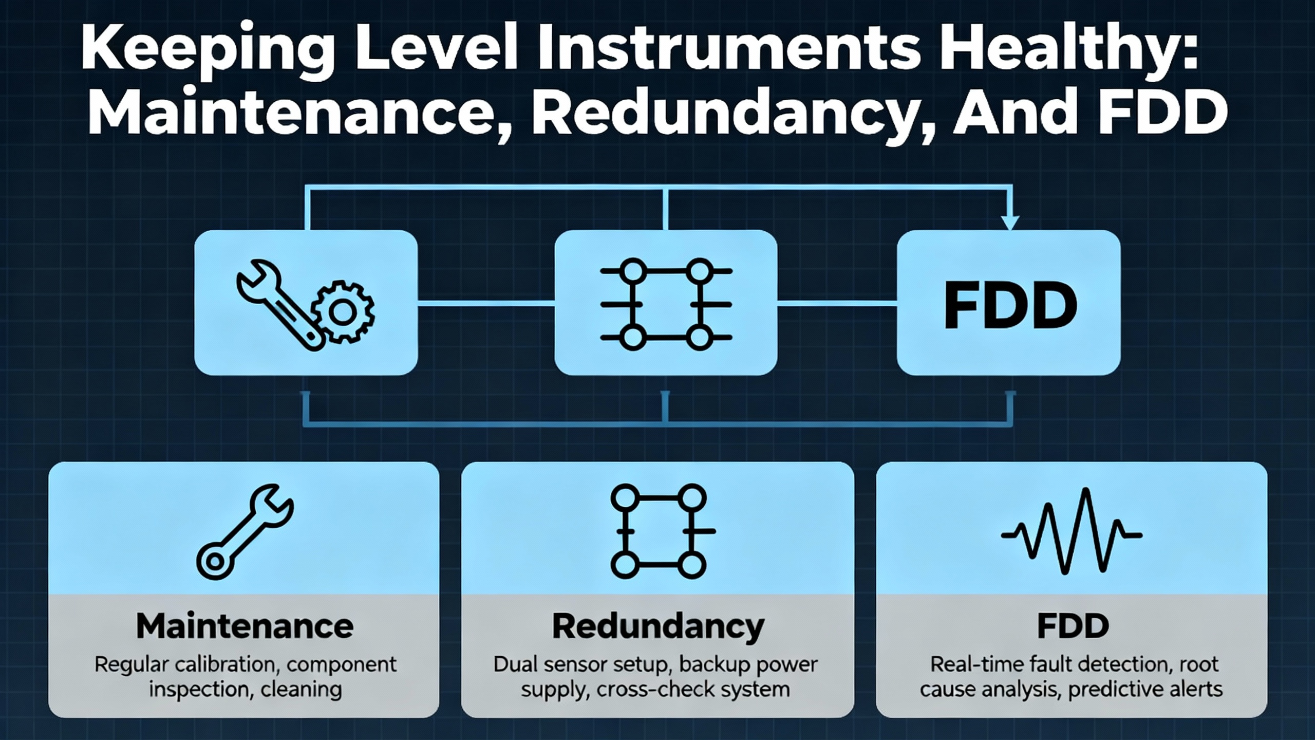
Keeping Level Instruments Healthy: Maintenance, Redundancy, And FDD
Running plants reliably is not just about fixing faults; it is about preventing them. Field-instrument studies and practical guidance from sensor vendors point to several effective strategies for level devices.
Regular inspection and cleaning are foundational. In high-humidity or corrosive settings, cleaning sensor surfaces and measuring elements, inspecting for fouling or buildup, and checking signal cable integrity catch many problems early. For radar sensors, this includes cleaning antennas and verifying that protective housings are intact. For ultrasonics, it includes removing deposits and ensuring stilling pipes remain clear.
Periodic calibration corrects drift and maintains accuracy over the life of the instrument. For critical tanks, scheduling calibration as part of a broader instrumentation program pays for itself in avoided downtime. Some modern sensors offer self-diagnostics and automatic calibration functions to reduce manual service, but they complement rather than replace an organized maintenance plan.
Alarm management matters as well. When frequent level alarms occur without real process abnormalities, this is a symptom of poorly chosen thresholds or changed process conditions. Tuning alarm setpoints to reflect actual operating ranges reduces nuisance alarms and preserves operator trust. Fault-diagnosis literature emphasizes the need to balance sensitivity against false alarms; the same logic applies directly to level alarms.
Emergency response planning for level-sensor malfunctions is another best practice in water and tank applications. Articles on handling water-tank sensor failures recommend clear procedures for comparing sensor readings with actual levels, triggering recalibration or further investigation when discrepancies appear, and having immediate containment measures ready when faulty readings could cause overflow or dry-run conditions. Staff training and drills ensure that operators recognize sensor-related anomalies quickly and act under time pressure.
Redundancy is an increasingly practical tool. Having spare sensors or a backup level measurement method, even if simpler, allows rapid replacement and reduces downtime. In more advanced systems, redundant sensors and cross-checking logic form the basis of fault detection and diagnosis. Research in sensor fault detection, including work in HVAC systems and broader process industries, shows that combining models, pattern recognition, and redundancy can detect sensor faults, isolate which device is at fault, and even reconstruct missing or corrupted measurements from healthy sensors. While not every plant needs sophisticated soft-sensor schemes, the principle of independent checks on critical level measurements is sound.
Technology Comparison At A Glance
The following table summarizes typical issues and practical solutions across several common level technologies, drawn from the application notes and troubleshooting guides discussed above.
| Level Technology | Typical Problems | Practical Solutions |
|---|---|---|
| Capacitance | Temperature drift, wall effects, high viscosity and salt contamination causing false readings | Use temperature-compensated, high-resolution sensors; smooth tank walls; keep contamination below roughly 0.07 oz per gallon; match probe design to fluid |
| Magnetic float | Sticking floats from poor welds or mechanical damage; confusing logic states in controllers | Inspect and reweld restricted chambers; verify float travel mechanically; clarify diagnostic codes and logic mapping in the control system |
| Radar | Range mismatch, unstable voltage, blocked or scarred antenna, interference echoes, mis-set height parameters | Select proper range; stabilize power supply; clean and protect antenna; mount away from internals and inflows; correctly set installation height and echo-processing parameters |
| Ultrasonic | Turbulence, foam and steam, blind zones, sensitivity to temperature and vapors | Install stilling pipes; manage foam formation and steam exposure; mount to avoid blind zones; monitor temperature and apply appropriate signal processing |
| Guided microwave | Probe length and mounting issues, reflections from nearby metal, foam conductivity effects | Use correct-length probes; choose coaxial probes near metal; keep disturbing objects out of field of view; avoid highly conductive foam when possible |
| Hydrostatic/pressure | Mis-specified tank geometry or fluid properties, density changes, vapors, corrosive attack | Fully specify tank shape and size; confirm fluid density and operating conditions; select materials for corrosion; recalibrate when process fluids change |
| Mechanical and switches | Fouling, sticking floats, lack of remote indication, misinterpreted states | Clean and inspect regularly; use as independent reference where possible; wire and configure logic carefully for clear alarm behavior |
This table is not exhaustive, but it captures the recurring patterns that show up in both vendor documentation and real-world troubleshooting.
Short FAQ
How do I tell if a level problem is in the sensor or in the process?
Start by comparing the sensor reading with an independent check, such as a sight glass, dip measurement, or another instrument. If both disagree with expectations, suspect the process, for example foam, a blocked outlet, or unexpected inflows. If the independent check looks correct and the sensor does not, focus on the instrument chain: power, wiring, configuration, and the sensor itself. Reviewing trends and event logs around the time of the problem also helps distinguish sudden process events from gradual sensor drift.
When should I replace a level transmitter instead of recalibrating it?
If a transmitter cannot be calibrated to a proper zero or span even after verifying power, wiring, and configuration, or if you observe physical damage such as a dented diaphragm, cracked housing, or persistent moisture intrusion, replacement is usually the right call. Manufacturer bulletins explicitly classify some conditions, such as an inability to adjust below a certain output current or visible diaphragm damage, as signs of a damaged sensor that should be repaired or replaced rather than repeatedly adjusted.
What is the single most common mistake with radar and ultrasonic level sensors?
The most common mistake is treating them as plug-and-play devices and ignoring the application details. For radar, that shows up as range and height parameters that do not match the actual tank, contaminated antennas, and mounting in areas full of internals and inflows. For ultrasonics, it appears as poor consideration of turbulence, foam, steam, and blind zones. In both cases, carefully matching the sensor to the tank geometry and process conditions, and strictly following the installation recommendations, prevents more problems than any clever control-room fix.
In industrial projects, clients remember the partners who help them make problems go away without drama. Level sensor faults are rarely glamorous work, but when you understand the physics, respect the process, and follow a structured diagnostic path, they become manageable engineering tasks instead of midnight emergencies. That is the mindset I bring to every tank and every transmitter: methodical, practical, and focused on giving operations a measurement they can trust.
References
- https://qed.usc.edu/papers/SharmaGG10.pdf
- https://pmc.ncbi.nlm.nih.gov/articles/PMC11053866/
- https://docs.nrel.gov/docs/fy25osti/77487.pdf
- https://ntrs.nasa.gov/api/citations/20090033812/downloads/20090033812.pdf
- https://www.researchgate.net/publication/382116309_Sensor_Fault_Detection_and_Diagnosis_Methods_and_Challenges
- https://www.plctalk.net/forums/threads/level-sensor-accuracy-problem.72324/
- https://forum.aquariumcomputer.com/showthread.php?9034-Level-sensor-problems
- https://holykell.com/Common-Problems-and-Troubleshooting-of-Radar-Level-Sensor.html
- https://jiweiauto.com/common-faults-troubleshooting-field-instruments.html
- https://www.rikasensor.com/a-how-to-handle-water-tank-level-sensor-malfunctions-in-critical-situations.html
Keep your system in play!
Top Media Coverage
Categories


Related articles Browse All
-
 amikong NewsSchneider Electric HMIGTO5310: A Powerful Touchscreen Panel for Industrial Automation2025-08-11 16:24:25Overview of the Schneider Electric HMIGTO5310 The Schneider Electric HMIGTO5310 is a high-performance Magelis GTO touchscreen panel designed for industrial automation and infrastructure applications. With a 10.4" TFT LCD display and 640 x 480 VGA resolution, this HMI delivers crisp, clear visu...
 -
 BlogImplementing Vision Systems for Industrial Robots: Enhancing Precision and Automation2025-08-12 11:26:54Industrial robots gain powerful new abilities through vision systems. These systems give robots the sense of sight, so they can understand and react to what is around them. So, robots can perform complex tasks with greater accuracy and flexibility. Automation in manufacturing reaches a new level of ...
 -
 BlogOptimizing PM Schedules Data-Driven Approaches to Preventative Maintenance2025-08-21 18:08:33Moving away from fixed maintenance schedules is a significant operational shift. Companies now use data to guide their maintenance efforts. This change leads to greater efficiency and equipment reliability. The goal is to perform the right task at the right time, based on real information, not just ...


- Q&A
- Policies How to order Part status information Shipping Method Return Policy Warranty Policy Payment Terms
- Asset Recovery
- We Buy Your Equipment. Industry Cases Amikong News Technical Resources Why choose us
- ADDRESS
-
 32D UNITS,GUOMAO BUILDING,NO 388 HUBIN SOUTH ROAD,SIMING DISTRICT,XIAMEN
Leave Your Comment