
-
Please try to be as accurate as possible with your search.
-
We can quote you on 1000s of specialist parts, even if they are not listed on our website.
-
We can't find any results for “”.
Servo Drive Alarm Code Guide: Understanding Error Messages
As a systems integrator who has commissioned and supported hundreds of servo axes across packaging lines, CNC cells, robots, and high‑speed conveyors, I treat alarm codes as a conversation with the drive. The drive is telling you what it does not like, where it hurts, and how urgent the situation is. Decoding that message quickly—and acting methodically—keeps your uptime high, your mechanics healthy, and your electrical team out of weekend call‑outs. This guide translates typical servo drive alarm codes into plain language, shows how different vendors present similar conditions, and lays out a field‑tested workflow that resolves faults without guesswork.
What Servo Drives Are Actually Doing When They “Alarm”
A servo system is a motor with a feedback device—most often an encoder—in a closed loop that regulates current, speed, and position. The drive (amplifier) takes commands from a controller, compares feedback to command, and corrects the error in real time. Anaheim Automation explains this layered control clearly: modern servos embed current, speed, and position loops and rely on negative feedback to keep error near zero. That sophistication is exactly why drives alarm. When measured variables leave safe or expected limits, the drive raises a code and often inhibits motion to protect people and equipment.
Manufacturers organize faults into categories that mirror the physics and electronics under the hood. Typical families include power anomalies, current and thermal protections, mechanical overloads, feedback and communications errors, parameter or memory problems, and main‑stage hardware faults. While naming and numbering differ by brand, the underlying causes and first checks are highly consistent. Industrial Automation Co., Unitronics, Omron, ABB, and FANUC all surface variations of the same themes.
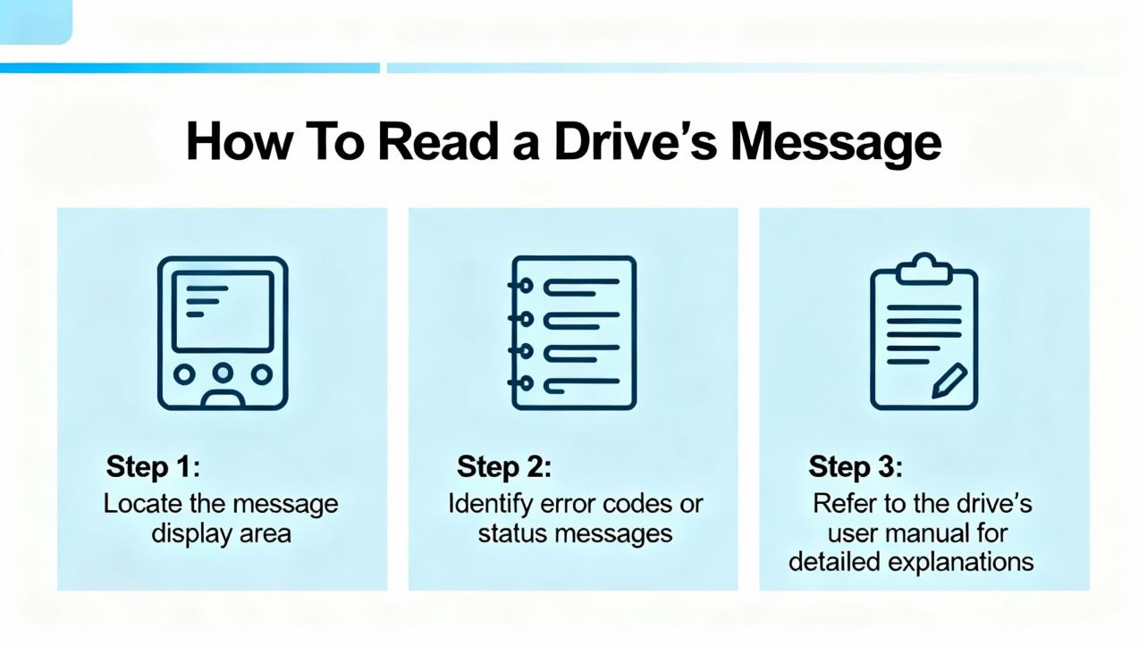
How To Read a Drive’s Message
Alarm codes carry structure and meaning beyond the short text on a panel.
Some vendors use alphanumeric families that cluster related issues. Omron examples include A.30 for overvoltage and A.31 for undervoltage, while A.10s and A.12s show up around overload and overcurrent. Unitronics uses A.13 for overvoltage and A.14 for undervoltage, reserves A.01 for parameter initialization problems, and assigns ranges for communication, encoder, and regeneration faults.
Some vendors use human‑readable mnemonics. FANUC’s legacy drives flash HV for DC link over‑voltage, LV for low voltage, and OVC for overcurrent. FANUC Alpha amplifiers add dot notation, where a code with a trailing dot indicates an IPM (power module) variant versus a plain overcurrent on that axis; for example, 8 indicates L‑axis overcurrent, while 8. denotes an L‑axis IPM alarm.
Some vendors include severity and context. ABB exposes DC link overvoltage, undervoltage, short‑circuit, and heatsink temperature alarms with clear names and frame‑class thresholds. Many platforms distinguish latching trips that require power cycling or explicit reset from non‑latching warnings you can clear via discrete inputs or software.
Two practical implications follow. First, never clear an alarm before you understand it; a reset is not a repair. Second, the fastest path to root cause is to read the exact code, note what the machine was doing when it tripped, and consult the model‑specific manual. Industrial Automation Co. and MRO Electric both stress that cross‑referencing the exact code avoids chasing symptoms.
The Usual Suspects and What To Do First
Overvoltage and regenerative energy often show up after rapid deceleration, heavy overhauling loads, or aggressive motion profiles. Drives raise A.30‑type or HV alarms when the DC bus climbs too high. The fix is rarely in the PLC logic. Check for a correctly sized and wired braking resistor and verify that the deceleration ramps are realistic. A packaging line documented by Industrial Automation Co. cut overvoltage trips by roughly 95 percent after installing a proper braking resistor and softening decel—an outcome I have repeated in the field many times.
Undervoltage appears as A.31‑type or LV alarms and usually traces to input dips, a missing phase, a fuse or contactor issue, or loose mains terminals. Confirm supply within spec with a meter, tighten everything you can safely reach, and look for brownouts caused by other loads. If the DC link is low, do not ignore it; undervoltage can masquerade as feedback or current faults downstream.
Overcurrent and short circuit are among the most common motion‑stopping faults. Expect OVC or HCL/HCM‑family codes on FANUC and A.12‑family on Omron and Unitronics. Before you blame the drive, rule out mechanical binding, misalignment, or shock loads that spike torque. If the mechanics pass, test motor power cables phase‑to‑phase and to ground, inspect connectors for arcing, and only then suspect the amplifier’s power stage. The dot‑suffixed IPM alarms on FANUC Alpha are a hint that the power module itself may be at fault.
Overload and stall conditions happen when the drive has asked for elevated current for too long. Causes include undersized motors, sticky slides, duty cycles above design, or gains so aggressive that the servo is fighting itself. Back off acceleration and jerk, retune gains, and confirm that the motor has the torque margin the application needs. UpFix and Technoenvio both flag sustained overload as an early warning sign that deserves attention before windings or reducers are damaged.
Overtemperature alarms protect the electronics and the motor. A heatsink overtemp trip on ABB drives roughly at 239°F for certain frames and 257°F for larger frames is a clear sign to restore airflow and clean filters. Check that the drive’s fans spin freely and quietly. For motors, look for blocked air paths, debris on fins, and ambient temperatures above recommended ranges. If a cabinet feels hot to the touch, assume it is hotter inside; a small change like spacing drives for better convection can lower thermal stress dramatically.
Feedback and encoder issues present as A.80‑family Omron errors or A.50 and A.52–A.59 ranges on Unitronics. Symptoms include erratic movement, following errors, or inability to home. Secure the encoder cable at both ends, separate low‑level feedback wiring from motor power in the tray, and verify the encoder type and resolution match the drive’s parameters. For absolute encoders that rely on batteries, some platforms warn around 3.1 V and hard trip below roughly 2.5 V as Unitronics documents; replace batteries proactively, then power‑cycle to clear the absolute error. When an encoder has been replaced, record phase alignment before disassembly as Mitchell Electronics recommends, to avoid chasing new alignment‑induced errors.
Communication faults between the drive and the controller—EtherCAT, CAN, or RS‑485—are often simple. Check node addresses and baud rates, reseat connectors, replace suspect patch cables, and verify network termination. Keep encoder and communication lines out of the motor cable’s magnetic field. Anaheim Automation notes that RS‑485 Modbus networks can run up to about 4,000 ft when wired and terminated correctly; long runs magnify the cost of a loose connection.
Parameter and memory errors surface when settings are out of range, written during power‑down, or corrupted. Some platforms provide functions like Fn001 to reinitialize parameters and restore defaults; others maintain read‑only items that cannot be edited directly. If you have to reset a drive, always back up the current parameter set first. After a reset, restore only the parameters you actually need and retest in small steps.
Main circuit and hardware faults—power modules, short circuits, ground faults—demand caution. If a fault persists with the motor disconnected, the amplifier is likely at fault. If it disappears, inspect the motor and cable for phase shorts or insulation breakdown. ABB warns that ground‑fault detection is often more sensitive when the drive is idle; take that hint seriously. On FANUC Alpha, the dot‑suffixed codes can help you separate a pure overcurrent from an internal IPM failure.
Panel or mode mismatches can stop motion even when nothing is “broken.” ABB lists panel loss and local/remote conflicts as causes for trips; reviewing start/stop and reference selects clears many of these quickly.
A Cross‑Vendor Cheatsheet You Can Use on the Floor
Use this table to map what you see to first checks and example code families. These are illustrative patterns cited from vendor documentation and reputable guides. Always verify against your exact manual.
| Alarm Category | What You’re Seeing | First Checks | Example Vendor Code Patterns | Direction of Fix |
|---|---|---|---|---|
| DC link overvoltage | Trips on decel or with overhauling loads | Measure mains, verify braking resistor sizing and wiring, soften decel | Omron A.30; Unitronics A.13; FANUC HV; ABB DC overvoltage | Add or resize braking resistor, tune motion profile, enable overvoltage control where supported |
| DC link undervoltage | Trips on start, heavy load, or line sag | Check for missing phase, blown fuses, loose mains, transformer tap | Omron A.31; Unitronics A.14; FANUC LV; ABB DC undervoltage | Stabilize supply, correct wiring, repair upstream components |
| Overcurrent or short | Immediate trip on move or enable | Inspect mechanics for binding; test motor cable insulation; check ground | Unitronics A.12; FANUC OVC, HCL/HCM; ABB short‑circuit | Fix wiring or motor faults; repair or replace amplifier if IPM alarm |
| Overload or stall | Sustained high current, axis stalls | Reduce accel/jerk; verify sizing and duty; retune gains | Omron A.10 family; Unitronics overload A.04 | Adjust profile; retune; resize motor if needed |
| Overtemperature | Heatsink or motor too hot | Clean filters; verify fans and airflow; check ambient | Omron A.40/A.41; ABB heatsink overtemp around 239°F–257°F | Improve cooling, lower duty, correct cabinet ventilation |
| Encoder/feedback | Erratic position, home failure | Reseat encoder cable; separate from power; verify type/resolution | Omron A.80/A.86; Unitronics A.50/A.52–A.59 | Repair cable; replace or realign encoder; correct parameters |
| Absolute battery | Battery low or absolute error | Replace battery; power cycle; clear absolute error function | Unitronics A.48 warning and A.47 trip | Preventive battery changes; confirm timestamp reset |
| Communication/network | PLC to drive link lost | Verify addressing and baud; replace patch cables; check termination | Omron A.C8/A.C9; Unitronics A.60–A.67 | Restore proper network wiring and settings |
| Parameter/memory | Invalid value or write failure | Back up; initialize; reload sane parameters; avoid editing read‑only | Omron A.02/A.04; Unitronics A.01/A.98 | Restore defaults then re‑enter required parameters |
| Regeneration path | Resistor fault or excessive regen | Inspect resistor wiring; verify capacity; jumper correctness | Unitronics A.15/A.16; ABB chopper sizing guidance | Repair wiring; choose proper resistor; retune decel |
| Main circuit hardware | Power stage or ground fault | Disconnect motor; re‑test; megger as trained; inspect for damage | FANUC dot‑suffixed IPM codes; Omron A.70–A.73 family | Replace amplifier; repair motor or cabling as indicated |
| Panel/mode mismatch | Panel loss or LOC/REM conflict | Check panel cable; review start/stop and reference selects | ABB panel loss and mode mismatch events | Correct mode, restore panel communications |
Vendor Patterns Worth Knowing
Omron’s alphanumeric families (A.30 overvoltage, A.31 undervoltage, A.80–A.86 encoder issues, A.40/A.41 thermal) are consistent across series, though exact semantics vary. Unitronics documents a broad A.01–A.82 scope, including power anomalies, encoder functions like Fn010 to clear absolute errors, and communication ranges A.60–A.69. FANUC’s HV, LV, OVC mnemonics and the dot suffix convention on Alpha amplifiers speed triage considerably; a plain 8 points to axis overcurrent while 8. points to IPM trouble. ABB’s documentation provides clear names and thermal thresholds by frame class and emphasizes chopper and resistor sizing to manage regenerative energy.
These patterns are drawn from vendor documentation and technical blogs by Industrial Automation Co., MRO Electric, and others. Treat them as a head start, not a substitute for your exact manual.

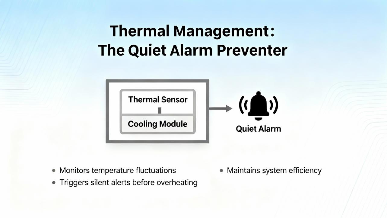
Thermal Management, The Quiet Alarm Preventer
I have lost count of how many “mystery” faults were resolved by a shop‑vac and a new fan. Heatsink trips on drives and stator overtemp estimates on motors accelerate as filters clog and ambient creeps up. Some ABB frames trip near 239°F and other frames near 257°F on the radiator; many panels reach that on a hot afternoon with doors closed. Keep vents clear, space drives so they can breathe, and look for airflow shadows in crowded cabinets. If you hear a fan squeal, replace it before it stops. When a drive mounts inside an enclosure, treat every watt of dissipation as heat you must remove.
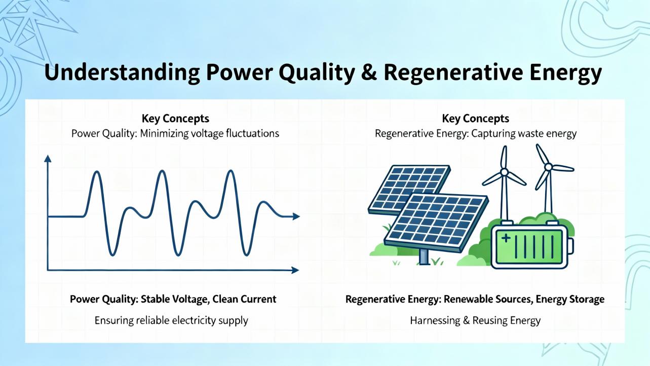
Power Quality and Regenerative Energy
Overvoltage is not a software bug. It is physics. Fast decel of a heavy load sends energy back into the DC bus. Without a place to go, the voltage rises until the drive protects itself. Match your braking resistor to the inertia and duty of the axis, wire it correctly, and confirm any jumpers or options that arm the chopper are installed per the manual. Then reshape motion profiles so decels are long enough for the resistor to work. Industrial Automation Co. describes a packaging line where those steps cut trips by about 95 percent; that mirrors what I see in practice.
Undervoltage is the evil twin. It arrives with sags, missing phases, undersized transformers, or marginal upstream contactors. Use a meter to confirm input, tighten every terminal you can safely reach, and prioritize a clean feed. The DC link and control rails are the foundation for everything else.
Feedback Integrity and Batteries
Encoders define where you are and how fast you are getting there. Add electrical noise or a loose connector and you get jitter, following error, or spurious overspeed trips. Separate encoder cables from motor power, ground shields properly, and verify encoder type and resolution in the drive. If you work with absolute encoders, add battery maintenance to your PM plan. Unitronics notes warnings around roughly 3.1 V and trips below about 2.5 V on certain platforms; while thresholds vary by brand, the principle is universal. Swap the battery during scheduled downtime and clear the absolute error properly so you do not discover it during first shift.
Resolvers exist for harsh environments and long life; encoders deliver higher accuracy and simpler integration. Anaheim Automation recommends encoders as the default unless your environment demands resolver durability.
Communications: Small Settings, Big Consequences
EtherCAT, CAN, RS‑485 Modbus and similar buses are robust until connectors are not. Many “random” servo trips owe to a mis‑keyed node address, a swapped pair, or missing termination. Keep high‑level comms away from high‑current motor leads, and set baud rates and update cycles to sane values. Anaheim Automation documents RS‑485 networks supporting dozens of drives across about 4,000 ft when wired and terminated correctly. Treat that range as a budget for good practice, not an invitation to push limits.
A Field‑Proven Triage Workflow
When a line stops and a drive is red, take sixty seconds to freeze the scene. Note the code, the motion state, and recent changes. If you have onboard alarm history, open it before you clear anything; the last ten to one hundred entries tell a story. Verify the power rails first with a meter if you can safely access them, then tug and reseat connectors from mains to motor to encoder. If the code points at feedback, switch the axis to jog and observe whether the position counts behave. If it points at current or overload, uncouple the load or reduce accel and see whether the trip disappears. If a code smells like parameter drift, back up, restore defaults, and re‑enter only what you need. Drive diagnostics and vendor tools such as Omron tuning software or Yaskawa’s DriveWizard save hours when used deliberately. Above all, change one thing at a time and record what you did. That discipline turns a frustrating afternoon into a repeatable fix.
These steps align with guidance from MRO Electric, Industrial Automation Co., and Mitchell Electronics, and reflect two decades of chasing down faults in hot cabinets on Friday afternoons.
Repair or Replace: Making a Rational Call
Not every red light means a new amplifier. If faults are isolated to bearings, fans, encoder cables, a tired braking resistor, or a scuffed PCB trace, repairs are quick and cost‑effective. UpFix reports customers saving well over $300 million in aggregate by repairing rather than replacing; that scale matches the savings I see when maintenance teams opt for component‑level fixes.
If you encounter persistent IPM trips, burnt windings, cracked power modules, or a drive so far behind in firmware and diagnostics that you spend more in downtime than the upgrade would cost, replacement is pragmatic. If the application has grown and the drive is undersized, replacing now prevents repeat trips. When you replace, take the opportunity to add better diagnostics, larger overload ratings, and options like integrated braking choppers and modern fieldbuses.
| Decision Factor | Repair Signals | Replace Signals |
|---|---|---|
| Fault scope | Cables, fans, encoders, parameter corruption, single board issues | Power module failures, repeated IPM trips, burnt windings, pervasive memory faults |
| Age and features | Recent model with good diagnostics and parts availability | Obsolete platform, poor diagnostics, limited support, missing safety or network options |
| Economics | Short downtime, low parts cost, clear root cause | Repeat trips, high parts and labor, production risk, opportunity to improve performance |
| Performance headroom | Properly sized, trips tied to specific events | Undersized, thermal and overload margins thin, application evolved |
Buying Tips From the Project Trenches
Choose feedback for the environment. Encoders are the right first choice in most cases, delivering higher accuracy and simple commissioning. Choose resolvers when heat, shock, or life‑cycle demands outweigh pure precision.
Check overload ratings and thermal headroom. A drive that offers three times peak current for short bursts, as some integrated solutions do, handles real‑world moves better than one that trips on every tight corner.
Think about regeneration and braking from day one. Specify braking resistors where inertia and cycle times demand them, confirm chopper options are present, and tune profiles with energy in mind.
Plan the bus. EtherCAT, CAN, and RS‑485 all work well when used within their strengths. Document node addresses, termination, and update rates. If you need distributed I/O or multi‑axis synchronization, verify those features before you order.
Value diagnostics and tools. Parameter management, real‑time plots, and autotuning matter when you are commissioning on a deadline. Platforms documented by Anaheim Automation and Omron offer these capabilities; they pay back quickly.
Mind space and wiring. Integrated motor‑drive‑encoder packages can cut wiring and panel space in compact machines. The tradeoff is thermal density at the axis; verify your airflow and mounting.
Think service and spares. Confirm repair options, parts availability, and training. Mitchell Electronics emphasizes proper tooling and skills for encoder alignment; make sure you either have them or a partner who does.
Care and Maintenance That Actually Prevents Alarms
Keep the airways clean. Fans, filters, and vents need attention on a cadence tied to your dust load. A clean cabinet runs cooler and trips less.
Tighten and inspect. Loose mains lugs, ground straps, and signal connectors are repeat offenders. A quarterly torque check prevents intermittent nightmare faults.
Back up parameters. Before you change anything, save everything. When a board fails, a clean parameter image turns a day into an hour.
Watch logs and temperatures. Many drives record last faults and internal temperatures. If you see heat trending up or the same code every Friday, that is your cue.
Lubricate and align the mechanics. Overcurrent and following errors disappear when slides are straight, couplings are aligned, and bearings are not crying for grease. Mitchell Electronics’ advice to distinguish electrical from mechanical saves time and parts.
Takeaway
Servo drive alarms are not riddles. They are structured, consistent clues to a physical problem. Learn the common categories—overvoltage and regen, undervoltage, overcurrent and overload, thermal, feedback, communications, parameters, and main‑stage hardware—and your troubleshooting will move from trial‑and‑error to targeted fixes. Start with safe power and clean wiring, confirm feedback integrity, decouple the load when possible, tune conservatively, and use the vendor’s diagnostic tools. Repair when faults are isolated and the platform is modern; replace when hardware is failing repeatedly or the application has outgrown the system. That is how you keep lines running and weekends free.
FAQ
Q: Why does my drive trip on overvoltage mostly during deceleration? A: Decelerating a load returns energy to the DC bus. Without a properly sized braking resistor and realistic decel ramps, the bus voltage rises until the drive trips to protect itself. Adding or resizing the resistor and softening decel usually resolves this. This is grounded in vendor documentation and case studies; confidence is high.
Q: I replaced an encoder and the axis now hunts. What did I miss? A: Verify the encoder type and resolution match the drive settings, confirm phase alignment if the platform requires it, and separate feedback cabling from motor power. A small misconfiguration or alignment error can force the control loop to fight itself. This advice blends documented guidance with field practice; confidence is high.
Q: Can I just reset a servo alarm and keep running? A: A reset only clears the symptom. If you do not remove the root cause—like a loose mains lug, a failing fan, or a mis‑sized motion profile—the alarm will return and may damage equipment. Vendors and service providers emphasize fixing the cause before clearing; confidence is high.
Q: When should I choose a resolver instead of an encoder? A: Choose resolvers for harsh environments where heat, shock, or lifespan are priorities and the absolute highest accuracy is not required. Otherwise, encoders are easier to integrate and more precise. This reflects Anaheim Automation’s guidance and integration experience; confidence is high.
Q: My absolute encoder alarm mentions a low battery. Do I have to power cycle after replacement? A: Many platforms require a full control power cycle after swapping the battery to clear the absolute error and re‑establish position tracking. Some also provide a function to clear the error. Unitronics documents this behavior; brand specifics vary. Confidence is high for the general requirement and medium for exact steps without your manual.
Q: Should I repair a drive with repeated IPM faults or replace it? A: Persistent IPM alarms typically indicate a failing power stage. If the drive is older or trips recur after repair, replacement is more reliable and economical. If the platform is current and the failure is isolated, repair can still be a good choice. This combines service data from providers and field experience; confidence is high.
Sources Consulted
Anaheim Automation for servo fundamentals, integrated solutions, networking ranges, and tuning tools; Industrial Automation Co. for fault categories, practical fixes, and a documented overvoltage case reduction; Omron for fault code families and diagnostics; ABB for drive fault categories and thermal thresholds by frame; Unitronics for detailed alarm scopes, parameter functions, encoder battery thresholds, and communication fault ranges; FANUC for mnemonic code conventions and dot‑suffixed IPM indicators on Alpha amplifiers; MRO Electric Blog for technician‑oriented troubleshooting steps and code interpretation; Mitchell Electronics for separating electrical from mechanical causes and practical diagnostic training; UpFix and Technoenvio for common symptoms, causes, and repair considerations across applications.
If you want this guide tailored to your exact drive model and firmware, share a recent fault log and a photo of the nameplate, and I will map your codes to vendor‑specific remedies and recommended parameter checks.
References
- https://www.diva-portal.org/smash/get/diva2:1045004/FULLTEXT01.pdf
- https://www.researchgate.net/publication/344018838_A_Review_on_The_AC_Servo_Motor_Control_Systems
- https://blog.upfix.com/common-signs-your-servo-is-faulty
- https://kwoco-plc.com/omron-servo-drive-alarm-codes/
- https://www.mitchell-electronics.com/diagnosing-servo-motor-issues-electrical-or-mechanical/
- https://www.robots.com/articles/understanding-error-codes-in-fanuc-robots
- https://www.sahinbearing.com/blog/servo-motor-alarm-list-meanings-and-correction-settings
- https://technoenvio.com/servo-alarms-causes-and-solutions/
- https://thmhuade.com/how-to-troubleshoot-servo-motor-issues-in-industrial-automation/
- https://anaheimautomation.com/blog/post/servo-motor-guide?srsltid=AfmBOoo1e-S4Z566o0Khwgha9kCbNOGPFJ0nZkBaYTo3Hv-qDo0rtUkp
Keep your system in play!
Top Media Coverage
Categories


Related articles Browse All
-
 amikong NewsSchneider Electric HMIGTO5310: A Powerful Touchscreen Panel for Industrial Automation2025-08-11 16:24:25Overview of the Schneider Electric HMIGTO5310 The Schneider Electric HMIGTO5310 is a high-performance Magelis GTO touchscreen panel designed for industrial automation and infrastructure applications. With a 10.4" TFT LCD display and 640 x 480 VGA resolution, this HMI delivers crisp, clear visu...
 -
 BlogImplementing Vision Systems for Industrial Robots: Enhancing Precision and Automation2025-08-12 11:26:54Industrial robots gain powerful new abilities through vision systems. These systems give robots the sense of sight, so they can understand and react to what is around them. So, robots can perform complex tasks with greater accuracy and flexibility. Automation in manufacturing reaches a new level of ...
 -
 BlogOptimizing PM Schedules Data-Driven Approaches to Preventative Maintenance2025-08-21 18:08:33Moving away from fixed maintenance schedules is a significant operational shift. Companies now use data to guide their maintenance efforts. This change leads to greater efficiency and equipment reliability. The goal is to perform the right task at the right time, based on real information, not just ...


- Q&A
- Policies How to order Part status information Shipping Method Return Policy Warranty Policy Payment Terms
- Asset Recovery
- We Buy Your Equipment. Industry Cases Amikong News Technical Resources Why choose us
- Registered Address
-
32D Guomao Building, No.388, Hubin south Road, Siming district, Xiamen,Fujian, China

Leave Your Comment