
-
Please try to be as accurate as possible with your search.
-
We can quote you on 1000s of specialist parts, even if they are not listed on our website.
-
We can't find any results for “”.
Digital Input Module, 16 Channels, 24 VDC: How To Read The Specification Like A Systems Integrator
Why 16‑Channel 24 VDC Digital Inputs Are The Workhorse Of Modern Panels
In most factory panels I open today, the backbone of the control system is still a 24 VDC digital input rack. Sixteen‑channel modules are the sweet spot: dense enough to keep cabinets compact, but not so crowded that troubleshooting turns into archaeology.
From the controller’s point of view, a digital input module is the bridge between the plant floor and the PLC CPU. As Industrial Automation Co. explains, digital inputs represent simple binary states such as on or off, high or low, and let the controller decide whether a motor should start, a gate should close, or an alarm should sound. PLCDepartment describes these modules as the interface that turns raw switch and sensor signals into clean logic data for the CPU.
In this article I will walk through how I evaluate a “Digital Input Module, 16 Channels, 24 VDC” specification as a systems integrator. I will focus on what the numbers actually mean in the field, how they tie back to standards and silicon, and where the real risks and tradeoffs hide. The discussion is grounded in published work from sources such as Analog Devices, IEB Media, Siemens, Texas Instruments, NI, and Maple Systems, combined with the patterns I have seen on real installations.
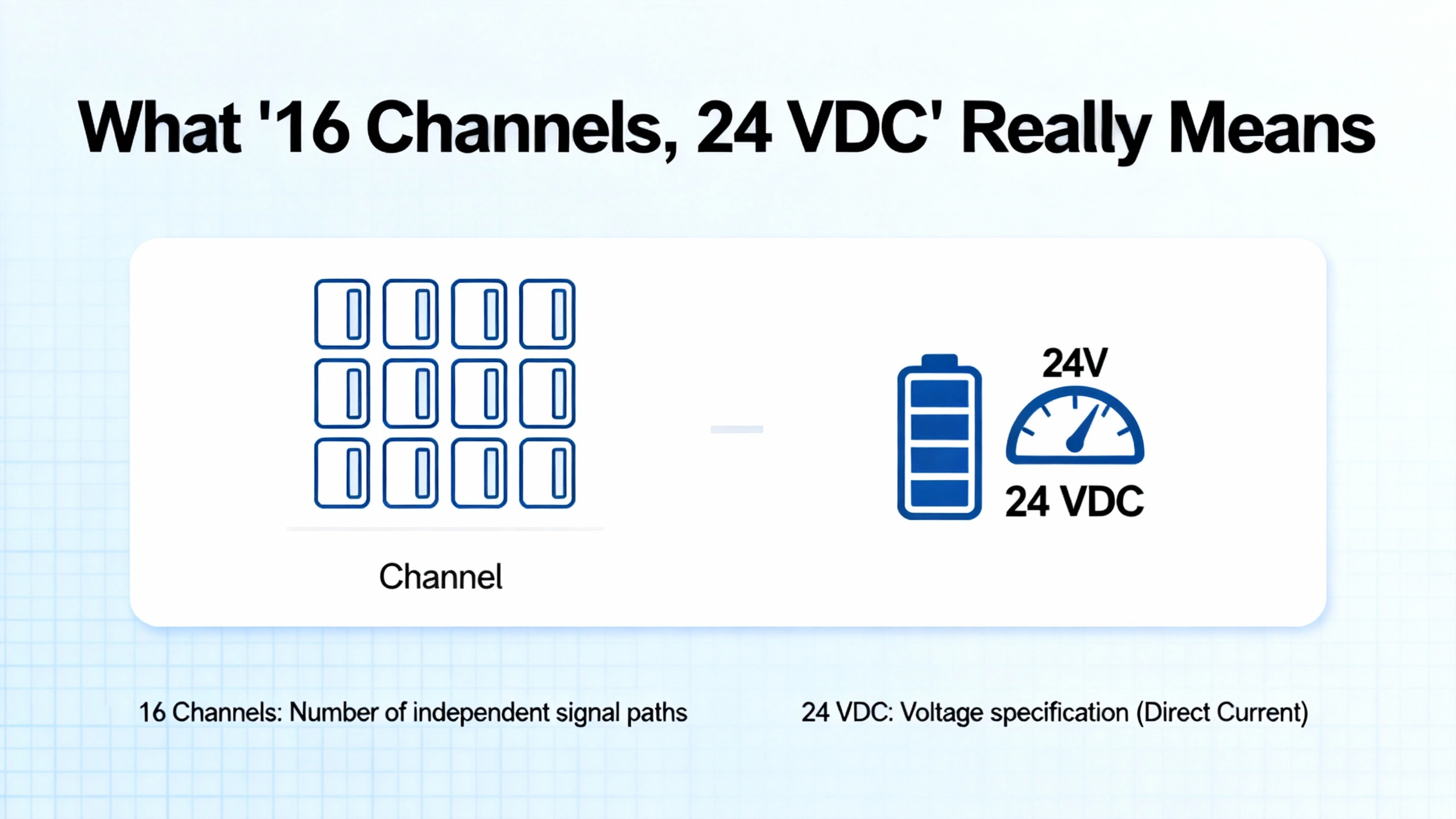
What “16 Channels, 24 VDC” Really Means
When a vendor describes a digital input module as “16 channels, 24 VDC,” there are three core ideas wrapped up in that simple label: the number of discrete points, the nominal field voltage, and the behavior of those inputs across their valid range.
Sixteen channels means the module can accept sixteen independent digital signals. PLCDepartment notes that each digital input channel is a separate point that sees the outside world as either energized or de‑energized. In a typical PLC rack, that might cover sixteen photoelectric sensors, or a mix of push buttons, limit switches, and proximity sensors.
The 24 VDC rating refers to the nominal field voltage the module expects from those devices. PLCDesign’s guidance is clear that digital input modules in industrial automation are “almost always 24 VDC,” with higher voltages reserved for very long runs or extreme electrical noise. There are good reasons: 24 VDC is touch‑safe, behaves well in noisy environments, and plays nicely on the same cable as 4–20 mA analog signals.
Behind that rating, a good specification will tell you the actual input voltage range. Modern integrated digital input ICs, such as the devices discussed in an Analog Devices article co‑authored with Rockwell Automation and in the IEB Media piece on high‑channel density modules, typically accept inputs up to around 40 V, even though they are intended for 24 V systems. That extra headroom is what lets a module survive a supply that is a little high or a long cable with induced noise.
Digital Versus Analog Inputs In Context
IndustrialAutomationCo reminds us that PLC inputs come in two broad flavors. Digital inputs deal exclusively in on or off states, whereas analog inputs represent a continuous range such as temperature or pressure. Digital input modules are simpler to process and troubleshoot, and they often have individual LEDs per channel so a technician can see signal state at a glance.
In a practical panel, that means you drive all your discrete interlocks, position switches, and presence sensors into the 24 VDC digital input module, while your pressure transmitters and temperature transmitters feed 4–20 mA into analog input modules. Trying to fake analog behavior with digital inputs or vice versa almost always leads to fragile logic.
Channel Density And Module Form Factor
Channel density is where 16‑channel modules shine. PLCDesign notes that for digital I/O, densities of 16 to 32 channels per module are common, with analog usually lower. At 16 channels you get good cost per point while still leaving enough room for isolation and thermal management.
Maple Systems’ documentation of its IO modules shows exactly this pattern: mixed digital input and output modules in the 16 in and 16 out range, packaged in compact housings that fit comfortably in a standard control cabinet. Datexel’s DAT3188‑4, although a different mix of four inputs and eight outputs, gives a sense of typical mechanical sizing, with a DIN‑rail housing roughly 4 in wide by about 4.75 in high and less than 1 in deep and a weight around 3 oz. A 16‑channel input module following the same design philosophy will have similar footprint and weight.
Electrical Specifications That Actually Matter
Beneath the headline rating, there are several electrical parameters that determine whether your 16‑channel 24 VDC digital input module will be robust or troublesome. This is where I spend most of my time when evaluating a spec sheet.
Voltage Levels And IEC Input Types
Industrial discrete inputs are not arbitrary; they are defined by IEC 61131‑2, which lays out standard 24 V input “types” with specific thresholds and currents. The IEB Media article on high‑density digital I/O makes an important point: a proper digital input module should support the IEC 24 V types 1, 2, and 3. Type 2, for example, requires at least about 6 mA of input current at the on level.
Analog Devices’ design note on 24 V digital inputs explains how devices like MAX22190 and MAX22199 are built to meet these requirements. For common Type 1 and Type 3 inputs, they set the input current to roughly 2.3 mA, just above the 2 mA minimum required by the standard, while ensuring the module can tolerate field voltages up to the relevant thresholds. For Type 2, the IEB Media article describes how channels can be paralleled and small reference changes made so the module can draw the higher current that the standard demands with minimal board changes.
When you read “24 VDC” on a 16‑channel spec, you should look for explicit mention of the IEC type supported and the exact on and off thresholds. If the vendor only says “24 V input” without stating type or threshold, you are taking on risk, especially when mixing different sensor and relay types.
Input Current, Relays, And Contact Cleaning
Siemens has a useful application note on pairing relays with digital input modules, and it addresses a problem I have seen many times on retrofit jobs. Mechanical relay contacts need a minimum current flowing through them to “clean” the contacts and ensure they do not build up oxide films. That minimum switching current is specified in the relay datasheet.
On the digital input side, Siemens tells you to look at the “input current for signal 1” in the DI module documentation. The goal is to match that typical input current to the relay’s minimum contact current. For example, if a relay requires at least 7 mA to stay clean, Siemens calls out a particular DI module with approximately 7 mA typical input current as a suitable match.
Modern low‑power digital input modules often cut input currents down to 2–4 mA in order to reduce heat, as documented in both the Siemens note and the IEB Media article. That is great for power, but if you connect those modules to legacy relays that expect higher currents, the contacts may never get properly cleaned. You may not see the problem at commissioning, but a few years later you get intermittent inputs that are extremely difficult to trace.
For a 16‑channel module, this can be a systemic issue. I treat “input current for logic 1” as a first‑class specification. If my field design uses traditional relay contacts, I match the DI current to the relay’s minimum spec. If the DI module is very low current, I use relays designed for low switching currents such as opto‑relays or relays with gold‑plated contacts, exactly as Siemens recommends.
Leakage, Holding Current, And Two‑Wire Sensors
NI’s guidance on matching digital I/O modules to digital output sensors goes into another subtle point: the behavior of two‑wire sensors. Two‑wire proximity sensors are wired in series with the load or input and draw a small current even when “off,” often called off‑state leakage or residual current.
According to NI, most industrial two‑wire sensors have off‑state leakage currents no higher than about 1.7 mA. That level is fine when they drive a motor or other low‑impedance load, but it can confuse a sensitive digital input that interprets anything above a threshold current as “on.” If your 16‑channel module expects almost zero current in the off state, a two‑wire sensor with 1.7 mA residual current can cause false ON signals.
NI also notes that in the on state a sensor requires a minimum holding current, typically in the 3 mA to 20 mA range. The digital input module must be able to sink or source at least that current for the sensor to latch reliably in the ON state.
For a 16‑channel 24 VDC module, the implication is straightforward. If your field design relies heavily on two‑wire sensors, you must verify two things in the spec: first, that the module’s off‑state sensing behavior tolerates the sensor’s leakage current without false ONs, and second, that each channel can handle at least the sensor’s minimum holding current. If the documentation does not address these directly, you are operating on hope rather than engineering.
Power Dissipation And Thermal Design At 16 Channels
Channel density is only a win if the module does not turn into a space heater. Here the IEB Media case study comparing discrete input designs to integrated digital input ICs is eye‑opening.
In a traditional discrete design, each input channel uses a simple resistor to limit current. With a 2.2 kΩ resistor at 24 V, each channel draws about 11 mA, dissipating roughly 264 mW. Eight of those channels already produce more than 2 W of heat. Scale to 32 channels and you are dumping more than 8 W into the board. In a compact 16‑channel module, the article reports power in the 4 W range using that discrete approach. That creates hot spots, stresses components, and can limit how many channels you can pack on a card before reliability suffers.
Integrated digital input ICs take a different approach. Instead of simple resistors, they use active current limiting. The IEB Media analysis shows a configuration where each channel is limited to around 2.6 mA. That cuts the per‑channel dissipation down to roughly 60 mW. The same article demonstrates that for 8, 16, 32, and 64 channels, total module power drops dramatically: from approximately 2.1, 4.2, 8.4, and 16.9 W in the discrete case to about 0.48, 0.96, 1.92, and 3.84 W using integrated devices.
For a 16‑channel 24 VDC module, that translates to a practical decision. A design built around discrete resistors will tend to run about four watts hotter than a design using integrated inputs. That extra heat must go somewhere, whether into cabinet air that bakes other electronics or into derating that limits ambient temperature. Integrated input ICs not only improve energy efficiency but also improve mean time between failures by avoiding those hot regions. For that reason, IEB Media explicitly recommends integrated IO ICs for any high‑density digital input or output module with eight or more channels, and I agree with that recommendation in real projects.
Isolation, Protection, And Diagnostics
A digital input module is an electrical firewall between field wiring and expensive controller electronics. Texas Instruments’ material on digital input modules emphasizes that isolated power and isolated data paths are fundamental: they protect low‑voltage logic from high‑voltage or noisy field environments.
Several sources converge on the same key capabilities. TI notes that a robust digital input module will provide galvanic isolation, advanced protection, and diagnostics. IEB Media points out that good integrated digital input devices offer ESD robustness on the order of plus or minus 15 kV air gap, surge tolerance around 1 kV, and the ability to operate from a wide field supply, roughly 7 to 65 V. TI adds that a precision signal chain, including input filtering and debounce filtering, is essential to interpret noisy field signals correctly.
Commercial I/O modules on the market reflect the same priorities. The Datexel DAT3188‑4 RS485 digital I/O module, although not a 16‑channel input device, illustrates typical isolation numbers: about 2000 Vac isolation between inputs, communications, and power supply, and an operating temperature from roughly 14°F up to 140°F with non‑condensing humidity up to about 90 percent. Contec’s overview of digital I/O boards shows how photocoupler‑isolated I/O improves noise immunity for 5 to 48 VDC and protects logic from field spikes.
Diagnostics are just as important as raw protection. IEB Media highlights that both digital input and output ICs now include rich diagnostics for per‑channel conditions such as overvoltage and overtemperature. TI’s digital output portfolio description mentions wire‑break detection, short‑to‑supply detection, and accurate current sensing feeding an ADC. Analog Devices’ MAX22190 and MAX22199 add SPI‑reported diagnostics such as low supply voltage alarms, overtemperature warnings, short circuits on reference pins, and wire‑break detection of field inputs.
When I specify a 16‑channel 24 VDC digital input module, I treat isolation level and diagnostic coverage as non‑negotiable. A module that simply reports ON/OFF without telling you about broken wires, miswiring, or thermal stress will cost time and money in troubleshooting.

Sensor Compatibility: PNP, NPN, Two‑Wire, Three‑Wire
Most headaches with digital input modules trace back to sensor compatibility rather than the module itself. Several of the referenced sources cover the key variations you must think through.
IndustrialAutomationCo describes the sourcing and sinking wiring conventions that underlie PNP and NPN sensors. In a 24 VDC system, a sourcing device (often PNP) supplies positive voltage to the input; a sinking device (often NPN) connects the input to ground. Contec’s discussion of digital input circuits reinforces this by distinguishing sink‑compatible and source‑compatible DC inputs, depending on whether they accept current from the sensor or sink current to ground.
What this means in practice is simple. A 16‑channel 24 VDC module will typically have its inputs wired either as sinking or sourcing, and you must match that to the PNP or NPN behavior of your field devices. Some modules support both, but only if the internal design supports it; you cannot simply swap wires and hope.
NI’s work on two‑wire and three‑wire sensors adds another dimension. Two‑wire sensors draw their power through the same line that carries the output signal and therefore always draw some current, even when “off.” As already discussed, that off‑state leakage can create false ON readings if the digital input module is not designed to handle it. Three‑wire or line‑powered sensors use a dedicated power terminal, so their leakage and burden current do not pass through the input channel in quite the same way.
The safe approach for a 16‑channel module is to treat sensor type as part of the spec. I make sure the module is explicitly rated for the combination of PNP or NPN and two‑wire or three‑wire sensors I plan to use, and I verify the current behavior against the numbers that NI and Siemens call out for leakage and holding current. Anything else is experimentation on a live plant.
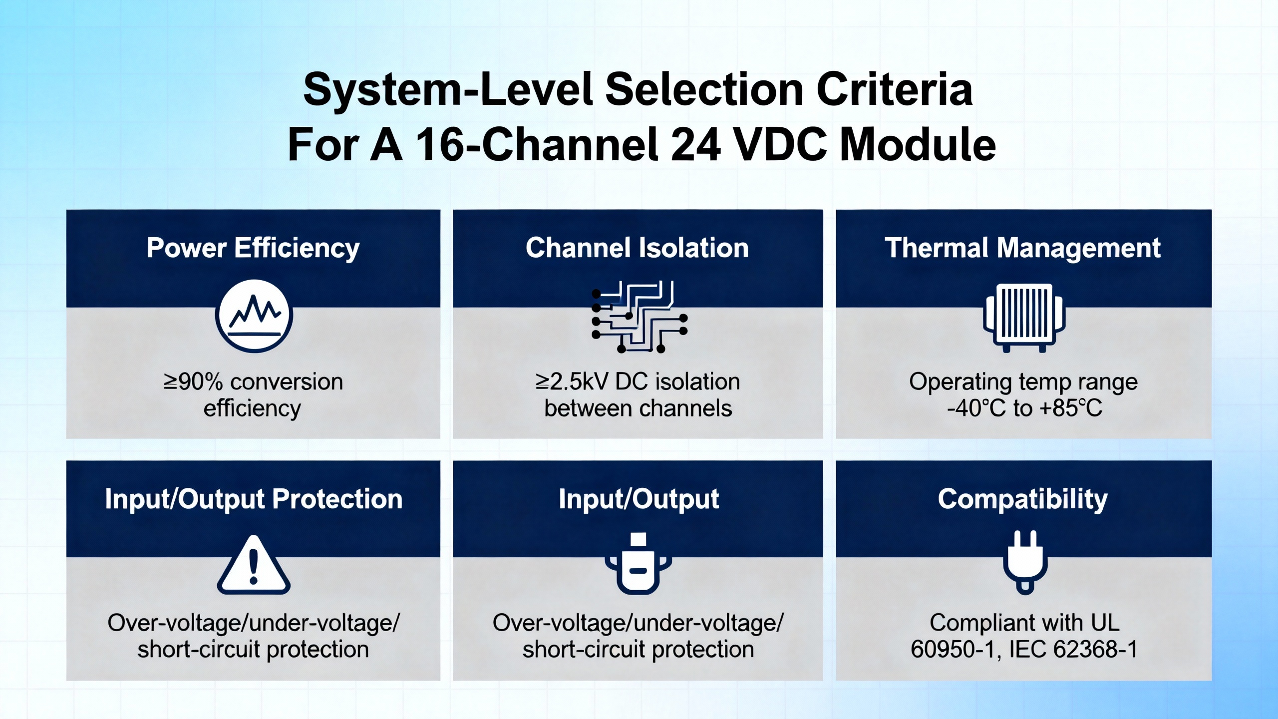
System‑Level Selection Criteria For A 16‑Channel 24 VDC Module
Once the electrical fundamentals are in place, the rest of the selection process is about system fit, lifecycle, and maintainability.
Maple Systems’ guidance on choosing PLCs stresses compatibility with existing hardware, communication protocols such as Ethernet and serial, and future scalability. Their article on PLC hardware features calls out the importance of matching I/O port types and counts to the actual demands of the application while leaving room for future expansion. ITG’s overview of I/O modules emphasizes modular, scalable designs so that modules can be added or removed as needs change.
Infineon’s discussion of digital I/O modules reinforces that the market is pushing toward scalable and flexible modules under strong space constraints. It also stresses that power consumption, functional safety, and system longevity must be weighed alongside cost. TI echoes this point: designers should prioritize isolation efficiency, robust protection, and accurate filtering, because those directly affect reliability and safety.
ZeroInstrument’s guidance on I/O modules recommends designing panels and racks with spare I/O capacity, often on the order of 20 to 30 percent extra channels. In my experience, that is exactly the margin that saves you when a late design change appears or when someone decides to add another sensor after startup. For a 16‑channel input module, I rarely plan to fill all sixteen points on day one. Instead, I size the rack so that roughly a quarter of the channels remain free for expansion.
Finally, you must consider how this 16‑channel digital input module fits into your communication and power architecture. Datexel’s DAT3188‑4 shows one common pattern: Modbus RTU or ASCII over RS‑485, with an optional RS‑232 version, and a supply in the 18 to 30 VDC range with reverse polarity protection. PLCDepartment highlights that remote or networked I/O options allow you to place modules near field equipment to reduce wiring runs. If you put a 16‑channel digital input module out on a machine, you must be comfortable with its network behavior, EMC compliance, and environmental ratings, not just its electrical thresholds.
Example Specification Snapshot
Pulling the threads together, it helps to see how the key parameters of a 16‑channel 24 VDC digital input module line up when you look through the lens of the referenced devices and design notes. The table below summarizes the sort of values and wording I look for, based directly on the published examples.
| Parameter | Typical range or description based on referenced designs |
|---|---|
| Channel count | 16 discrete digital input channels |
| Nominal field voltage | 24 VDC digital inputs, almost always used in practice, per PLCDesign |
| Input voltage range | On the order of 0 to about 30 V for logic, with tolerance up to around 40 V, as shown in Analog Devices and IEB Media examples |
| IEC 61131‑2 compatibility | Support for 24 V input Types 1 and 3 natively, with options to support Type 2 by adjusting channel configuration, per IEB Media |
| Input current, logic 1 | Typical values around 2.3 mA for low‑power integrated designs, meeting the 2 mA minimum for Type 1 and Type 3; higher currents around 6 to 7 mA for relay‑friendly modules, as discussed by Siemens |
| Off‑state leakage handling | Must tolerate up to roughly 1.7 mA residual current from two‑wire sensors without false ON, following NI’s guidance |
| Holding current capability | Channel must sink at least around 3 to 20 mA to keep two‑wire sensors latched ON, per NI’s range |
| Field‑side supply | Wide supply capability, often from roughly 7 to 65 V on the integrated IC side, per IEB Media and Analog Devices, with module supply commonly in the 18 to 30 VDC range similar to Datexel’s module |
| Isolation | Galvanic isolation between field, logic, and communication domains on the order of 2000 Vac, as seen in Datexel’s specification and Contec’s photocoupler designs |
| Power dissipation at 16 channels | Approximately 4.2 W for a discrete resistor design versus about 0.96 W for an integrated IC approach with current‑limited inputs, according to the IEB Media calculations |
| Diagnostics | Per‑channel and global diagnostics including wire‑break detection, overtemperature and overvoltage reporting, and SPI or bus‑level fault reporting, per Analog Devices, TI, and IEB Media |
| Environmental rating | Operating temperatures roughly 14°F to 140°F with non‑condensing humidity up to about 90 percent, as shown in Datexel’s example for a similar industrial I/O module |
When a vendor’s specification lines up with these ranges and capabilities, I am confident the 16‑channel 24 VDC digital input module will behave well in a typical industrial environment. When the spec is vague or silent on these points, I assume additional engineering validation and possibly lab testing will be required before deployment.

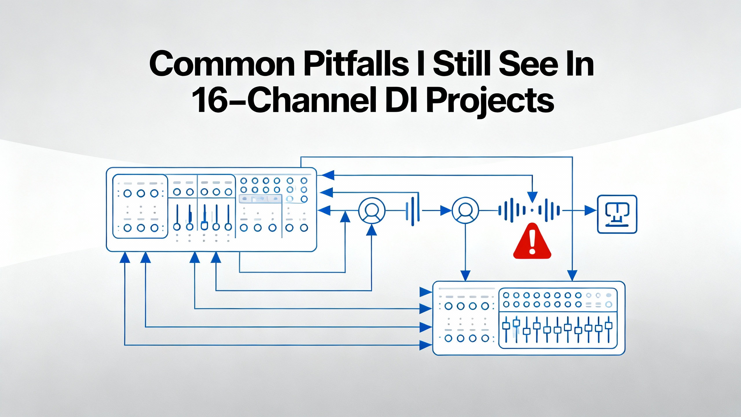
Common Pitfalls I Still See In 16‑Channel DI Projects
Even with good specifications available, several recurring mistakes show up in projects built around 16‑channel 24 VDC digital input modules.
One recurring issue is underestimating heat in high‑density racks. Engineers assume that because the module is only processing logic signals, power is negligible. The IEB Media numbers prove that assumption wrong for discrete designs: tens of channels at 11 mA each add up to serious wattage. When panels sit in warm environments without active cooling, those watts matter.
Another frequent problem is mismatching input current and relay contacts. Siemens’ warning about contact cleaning is not theoretical. I have walked into plants where half of the safety relays were feeding into ultra‑low‑current digital inputs designed for low‑power sensors. The system passed factory acceptance testing when everything was new, then developed intermittent faults years later as contacts aged. The cure was either to replace the digital input module with a higher current type or to replace the relays with low‑current models.
False ON indications from two‑wire sensors are also common. NI’s explanation of residual current makes it clear that you cannot treat two‑wire sensors like clean dry contacts. When a 16‑channel input module does not specify how it handles sensor leakage, you can end up chasing phantom activations that only occur at certain temperatures or cable lengths.
Finally, I see too many projects that fill every input on every module on day one, leaving no space for expansion. ZeroInstrument’s recommendation to leave roughly a quarter of channels unused is hard to argue with once you have gone through even one mid‑life plant upgrade. On a 16‑channel module, leaving three or four points free at first often costs less than adding new modules later or rewiring entire panels.
Short FAQ
What does “24 VDC rating” actually guarantee for a digital input module?
The 24 VDC rating means the module is designed around the IEC 61131‑2 24 V input standards. According to IEB Media and Analog Devices, a compliant design will recognize logic levels at the defined thresholds, draw at least the minimum input current for the selected type, and tolerate reasonable overvoltage up to about 40 V without damage. It does not mean the module can handle arbitrary higher voltages or miswiring, so you still must check the specified absolute maximum ratings and isolation levels.
Why not always choose the lowest input current to save power?
The IEB Media article shows why low input currents are attractive: they dramatically reduce power dissipation at high channel counts. However, Siemens and NI both warn that currents that are too low can cause trouble. Relay contacts may not be cleaned properly if the current is below their minimum switching value, and two‑wire sensors may not meet their minimum holding currents. In practice, you need enough current to satisfy relays and sensors, but not so much that you create thermal problems. Integrated digital input ICs help strike that balance by limiting current to a moderate fixed value instead of the higher currents set by simple resistors.
Can I freely mix two‑wire and three‑wire sensors on a 16‑channel 24 VDC digital input module?
NI’s classification of two‑wire versus three‑wire digital output sensors shows that they behave very differently. Two‑wire sensors always draw residual current and rely on the I/O module to sink both off‑state leakage and on‑state holding current. Three‑wire sensors draw their operating current from a dedicated supply terminal, which reduces the current burden on the input channel itself. Whether you can mix them on a given 16‑channel module depends entirely on the module’s design and specification. You must verify that each channel’s current handling and detection thresholds are compatible with both sensor types; otherwise, you risk false indications or unreliable switching.
Closing Thoughts
A 16‑channel 24 VDC digital input module looks simple on the surface, but behind that simplicity sits a stack of standards, silicon behavior, and field realities. When you read the specification through the lens of IEC types, input current versus relay and sensor requirements, power dissipation, isolation, and diagnostics, the differences between modules become stark. From the perspective of a systems integrator who will own the uptime, the best module is not the cheapest per point; it is the one whose numbers line up with the realities of your sensors, wiring, and environment and still leave you a margin for the next change order.
References
- https://www.datexel.com/rs485-digital-input-output-module-dat3188-4.html
- https://controlbyweb.com/x408/?srsltid=AfmBOopj5bxcfepdzwZ-8-GazsUOcILWXWCncJ-jaBo59sz65aaHBvjS
- https://www.infineon.com/application/digital-input-output
- https://www.linkedin.com/pulse/design-considerations-plc-io-choosing-sensors-relay-usabimana-tjbsf
- https://maplesystems.com/10-things-to-consider-when-choosing-new-plc/?srsltid=AfmBOopuHSHFRRE9AtFLj3wd8hOi-ekUfjENSd4jdFxczZtmyjIiqGnu
- https://toshiba.semicon-storage.com/info/application_note_en_20210325_AKX00763.pdf?did=70620
- https://www.ti.com/solution/digital-input-module
- https://zeroinstrument.com/understanding-i-o-modules-in-automation-systems-a-comprehensive-guide/
- https://industrialautomationco.com/blogs/news/understanding-the-differences-between-digital-and-analog-inputs-in-plcs?srsltid=AfmBOorvARHgW92E652zcEstwZZi1rxr6wQjdFLrGNELYAfyyjfVT0mi
- https://www.itgindia.com/blogs/what-is-an-i-o-module-and-its-crucial-role-in-industrial-automation/
Keep your system in play!
Top Media Coverage
Categories


Related Products
-
 Redundant Power SupplyManufacturer: Honeywell
 -
HIGH LEVEL ANALOG INPUT MODULEManufacturer: Honeywell
-
CONTROL PROCESSOR MODULEManufacturer: Honeywell
-
3300 XL 8 mm Proximity ProbesManufacturer: Bently Nevada
-
 Speed Control Proact ModuleManufacturer: Woodward
 -
POWER SUPPLYManufacturer: Honeywell
-
 FEEDER PROTECTION AND CONTROLManufacturer: ABB
 -
 OPERATOR INTERFACEManufacturer: Siemens
 -
DIGITAL OUTPUT CARDManufacturer: Honeywell
-
Fibre optic cableManufacturer: Honeywell

Related articles Browse All
-
 amikong NewsSchneider Electric HMIGTO5310: A Powerful Touchscreen Panel for Industrial Automation2025-08-11 16:24:25Overview of the Schneider Electric HMIGTO5310 The Schneider Electric HMIGTO5310 is a high-performance Magelis GTO touchscreen panel designed for industrial automation and infrastructure applications. With a 10.4" TFT LCD display and 640 x 480 VGA resolution, this HMI delivers crisp, clear visu...
 -
 BlogImplementing Vision Systems for Industrial Robots: Enhancing Precision and Automation2025-08-12 11:26:54Industrial robots gain powerful new abilities through vision systems. These systems give robots the sense of sight, so they can understand and react to what is around them. So, robots can perform complex tasks with greater accuracy and flexibility. Automation in manufacturing reaches a new level of ...
 -
 BlogOptimizing PM Schedules Data-Driven Approaches to Preventative Maintenance2025-08-21 18:08:33Moving away from fixed maintenance schedules is a significant operational shift. Companies now use data to guide their maintenance efforts. This change leads to greater efficiency and equipment reliability. The goal is to perform the right task at the right time, based on real information, not just ...


- Q&A
- Policies How to order Part status information Shipping Method Return Policy Warranty Policy Payment Terms
- Asset Recovery
- We Buy Your Equipment. Industry Cases Amikong News Technical Resources Why choose us
- ADDRESS
-
 32D UNITS,GUOMAO BUILDING,NO 388 HUBIN SOUTH ROAD,SIMING DISTRICT,XIAMEN
Leave Your Comment