
-
Please try to be as accurate as possible with your search.
-
We can quote you on 1000s of specialist parts, even if they are not listed on our website.
-
We can't find any results for “”.
16-Channel Digital Input Modules with Diagnostics: A Field Engineer’s Guide
When you have been commissioning control panels for a couple of decades, certain pieces of hardware quietly become the backbone of every project. A 16-channel digital input module with decent diagnostics is one of those workhorses. It is not glamorous, but it is exactly where your safety circuits, interlocks, and “this machine is really running” signals show up. Get this part of the design right and your start-up is calm. Get it wrong and you spend nights chasing ghost signals and unexplained trips.
This article walks through how 16-channel digital input modules work, what modern diagnostic functions really do, and how to choose and apply them pragmatically. The discussion draws on practical guidance from industrial I/O references such as Industrial Electrical Warehouse and PLC Department, sensor and I/O application notes from National Instruments, Siemens, and Analog Devices, and concrete product examples from Beckhoff, Emerson, Campbell Scientific, and others.
What a 16-Channel Digital Input Module Actually Does
Programmable logic controllers and remote terminal units do not talk directly to push buttons, sensors, or relays. As Industrial Electrical Warehouse and PLC Department emphasize, that translation is handled by input and output modules. The CPU lives in a digital world; the I/O modules sit at the boundary and convert real-world electrical signals into clean logic and back again.
A digital input module is the half of that bridge that listens. It watches a set of discrete signals and reports each as either ON or OFF. Typical sources, as described in the PLC I/O references, include push buttons and selector switches, proximity and photoelectric sensors, mechanical limit switches, and dry relay contacts. In many plants those field devices all present signals around 24 V DC, which is the common control level in modern industrial systems.
A 16-channel digital input module simply packs sixteen of these field input circuits into a single piece of hardware. A compact example is Beckhoff’s EL1809 EtherCAT terminal, which provides 16 digital inputs for 24 V DC signals in a housing only about half an inch wide. Each channel has its own status LED, the inputs are specified as IEC 61131-2 type 1 or type 3 compatible for 24 V DC, and an internal 3 millisecond filter suppresses contact bounce from switches.
Other 16-channel units combine discrete and counting capability. Emerson documents a “16-channel DI/PI” module in its FB3000 family, where channels can act as standard digital inputs (for valve and alarm status) or as pulse inputs for metering signals. In data acquisition, Campbell Scientific’s SDM-IO16A is another 16-channel module that can be configured for input modes such as pulse counting and status monitoring when paired with their data loggers. In input mode its power draw is typically in the microamp to milliamp range, which matters in low-power installations.
Across these product families the concept is consistent. Each “channel” is a protected, conditioned input that senses whether a field signal meets the “ON” criteria and then encodes that state into a bit for the controller. Sixteen of those channels share a housing, a power feed, and usually a common internal reference for their 0 V side.
Diagnostic Functions: From LEDs to Deep Health Data
Early digital input cards gave you two clues: the PLC thought the bit was a 1 or a 0, and maybe an LED on the front panel. Today’s 16-channel modules can do much more, and the diagnostic features are worth understanding because they directly shorten troubleshooting time.
Local visual diagnostics
Beckhoff’s EL1809 illustrates the first layer: per-channel LEDs. Each of the sixteen inputs has a small indicator that turns on when the module recognizes the signal as high. PLC Department highlights similar front-panel indicators on general-purpose digital I/O modules, noting how they provide immediate feedback during wiring and maintenance. In practice, those LEDs let you determine in seconds whether a problem is in the field wiring or in the control program.
Input filters are another subtle but important diagnostic helper. The EL1809’s 3 millisecond filter, for example, is tuned to suppress the chatter when a mechanical contact closes. Industrial Electrical Warehouse notes that digital input modules often incorporate such filtering to avoid false triggers. From a field perspective, you see fewer “mystery” activations and you avoid chasing spurious alarms that were really just contact bounce.
Electronic self-diagnostics and health monitoring
Inside many 16-channel modules you will find specialized digital-input front-end ICs rather than discrete resistor networks. Analog Devices describes one such family in detail: the MAX22190 and MAX22199 industrial digital input devices. Each of these chips monitors eight 24 V DC current-sinking inputs and normally reports their states via a serial interface such as SPI, which is particularly attractive for high channel count modules because it minimizes the number of isolated logic lines.
Beyond the basic input function, these devices integrate diagnostics. According to the Analog Devices article, the MAX22190/MAX22199 can flag low power supply voltage, overtemperature conditions, short circuits on key reference pins, and wire-break events on field inputs. In other words, a module built with these front ends can do more than say “channel 5 is OFF.” It can say “channel 5 is OFF because the field wire is broken” or “the front-end chip is in an overtemperature condition.”
By default, all eight inputs on these ICs are enabled and their glitch filters are bypassed at power-up, with diagnostic features disabled. That behavior means a module can power up behaving like a traditional input card, yet still expose a richer diagnostic interface once the controller configures it over SPI.
Network-level and software diagnostics
On the system side, PLC Department notes that modern I/O modules often present status information and even self-diagnosis over fieldbus networks such as Ethernet-based protocols. Beckhoff’s EL1809, as an EtherCAT terminal, fits squarely into that category: it forwards its 16 isolated input states across the EtherCAT network to a central controller while also supporting modular power distribution and per-channel status LEDs in the cabinet.
On the software side, Schneider Electric’s community discussion around Control Expert illustrates a related trend. Instead of addressing inputs with raw register syntax like %I0.2.0.0, newer projects often use structured device data types (DDTs) such as DIS_CH_OUT[0].VALUE. Those structures can carry not only the ON/OFF bit but also diagnostic flags, timestamps, or quality indicators. In practice, that structured view is how you get value from diagnostic-rich hardware: you bring those additional bits into your application as named fields instead of leaving them buried in vendor-specific registers.

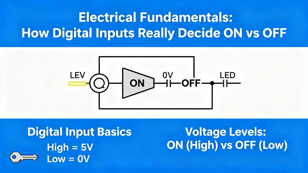
Electrical Fundamentals: How Digital Inputs Really Decide ON vs OFF
From a distance, a digital input is just “1 or 0.” When you are specifying or troubleshooting a 16-channel module, you need to think in terms of currents and thresholds instead. Several of the reference documents emphasize this, including standards-based guidance from Siemens and practical sensor notes from National Instruments.
IEC 61131-2 thresholds and current levels
Industrial digital inputs often follow IEC 61131-2 type 1 or type 3 characteristics for 24 V DC signals. Analog Devices’ article on the MAX22190/MAX22199 points out that for common type 1 and type 3 inputs, the input current is typically set to roughly 2.3 mA so that it is higher than the 2.0 mA minimum current required by the IEC standard for an ON state. In their design, most of that 2.3 mA field current is steered through an “energyless” LED driver for visual indication, while only about 160 microamps are consumed by the chip itself. That approach keeps the module’s power dissipation low while still meeting the standard’s current requirements.
The same article examines behavior close to the type 3 ON threshold. With a field voltage at 11 V, which is the defined ON threshold for type 3 inputs, measurements show that as the LED pin voltage increases toward 6 V, the field input current only decreases by about 0.6 percent. At slightly lower field voltages of 9 and 10 V, which lie in the transition region where no minimum current is mandated, the input current stays above 2 mA even when the LED pin is driven up to around 5.5 V. Those measurements confirm that the device can provide 5 V logic-level LED outputs and still satisfy the type 3 current requirement.
The details are specific to one IC family, but the principle generalizes. A 16-channel digital input module must both enforce and respect minimum current levels for an ON state, across tolerances and with any internal diagnostics active. Any diagnostic trick—such as repurposing LED drivers for logic outputs—has to be validated so that it does not pull the input current below what the standard and field devices require.
Two-wire and three-wire sensors: leakage and holding current
National Instruments explains another key piece of the puzzle from the sensor side. Digital output sensors can be broadly grouped as two-wire or three-wire devices, and their behavior directly affects which digital I/O modules are appropriate.
A two-wire sensor is wired in series with its load or with the input module. The same current path both powers the sensor’s internal electronics and represents its output signal. In the OFF state, the sensor still must draw a small operating current, commonly called off-state leakage or residual current, to keep its electronics alive. When such a sensor drives a low-impedance industrial load like a contactor coil, that residual current is usually harmless. However, if the load is the input of a digital I/O module that was not designed for that leakage, the I/O channel can falsely register an ON state. National Instruments notes that many two-wire sensors exhibit residual currents up to about 1.7 mA and recommends that digital input modules be specified to tolerate at least that off-state current without misdetecting.
In the ON state, a two-wire sensor also needs a minimum holding current, typically in the 3 to 20 mA range, to remain energized properly. If the I/O module cannot source or sink that minimum current, the sensor may not operate reliably, even if its voltage appears correct.
Three-wire sensors, sometimes called line-powered sensors, separate the supply and signal paths. They draw their operating current, often around 20 mA of burden current, through a dedicated excitation terminal. The digital input channel then receives a cleaner voltage-oriented signal. When pairing three-wire sensors with 16-channel input modules, you still must ensure that the module’s channel can handle the small signal currents and that the module or system can supply the burden current on the excitation lines.
From a systems perspective, a high-density 16-channel module is attractive, but you have to verify compatibility with the sensor mix. A cabinet full of two-wire proximity switches demands input channels that can withstand residual currents up to about 1.7 mA in the OFF state and provide sufficient holding current; otherwise, diagnostics will simply tell you that channels are “stuck ON” without solving the root cause.
Relay contacts and minimum current for clean operation
Siemens adds another nuance when digital inputs are wired to relay contacts. In their guidance on selecting digital input modules for relay status detection, they highlight the importance of minimum current through the relay’s working contacts. That minimum current, which you find in the relay’s data sheet, is needed to keep the contacts clean and avoid oxidation. If your digital input module draws less than that current in the ON state, the relay can operate mechanically while the contacts slowly degrade electrically, leading to intermittent or failed status readings.
The practical advice from Siemens is straightforward. When you choose a digital input module, check the input current specified for logic “1” and ensure it matches or exceeds the relay’s minimum current. In a worked example, a relay with a minimum current of 7 mA can be paired with a Siemens digital input module that typically draws 7 mA at logic “1,” and that combination is considered suitable.
Many modern low-power digital input modules, however, are engineered for significantly lower input currents, in the 2 to 4 mA range, to reduce power loss. Siemens notes that for such low-current inputs, you should use opto-relays or relays with gold-plated contacts that are designed for reliable operation at low currents. When your 16-channel module is part of a larger safety or interlock scheme relying on relay contacts, that subtle parameter—input current at ON—becomes a critical selection criterion.
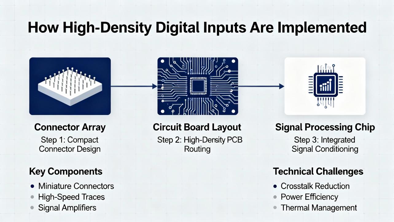
How High-Density Digital Inputs Are Implemented
High-channel-count input modules compress a surprising amount of design into a small housing. The Analog Devices digital input article sheds light on how this is done in practice.
The MAX22190 and MAX22199 devices monitor eight 24 V current-sinking inputs and normally report their state via a serial interface under the control of signals like SPI and latch pins. This serialization minimizes the number of logic signals that must cross galvanic isolation barriers, which is particularly beneficial in modules that host sixteen, thirty-two, or more channels. Fewer isolated logic paths mean smaller, more cost-effective isolation components and simpler backplane or fieldbus interfaces.
In some applications, however, pure serialization is not ideal. Analog Devices makes the point that serialization effectively time-quantizes the input signals, so you lose fine-grained timing information about when edges occur. In timing-sensitive systems, such as incremental encoders or high-frequency counters, that quantization and the latency of serial readout can cause trouble. A pure parallel logic interface, like that offered by their MAX22195 device, avoids serialization but requires more isolation channels.
Their article examines a clever hybrid approach: repurposing the eight LED driver outputs on MAX22190/MAX22199 as logic-level outputs. Normally the LED drivers draw the field input current and provide a visual ON/OFF indication for each channel, without consuming current from the module’s own power supply. Because those LED drivers are current outputs, resistors to ground can serve as simple transresistance elements to convert the current, about 2.3 mA typ per channel, into voltage signals that feed digital isolators or microcontrollers. With a resistor of around 1.5 kilohms, for example, the resulting voltage is approximately a 3.3 V logic level.
The data sheet’s absolute maximum rating of plus 6 V on the LED pins allows these outputs to be used safely as 3.3 V or 5 V logic outputs, as long as the resistor values keep the voltage below that 6 V limit. Analog Devices’ measurements confirm that even at 11 V field input and 6 V on the LED pin, the input current remains within about 0.6 percent of its nominal value, preserving IEC 61131-2 compliance for type 3 inputs.
They also investigate dynamic behavior. At a 10 kHz switching rate with a 1.5 kilohm load generating about 3.3 V, the LED outputs show clean transitions without overshoot or undershoot that might harm logic receivers. With glitch filtering disabled and input frequencies as high as 100 kHz, the LED outputs still track, though the rising edges exhibit an average propagation delay around 1 microsecond with roughly plus or minus 0.5 microseconds of jitter, attributable to internal sampling at about 1 MHz. Falling edges respond much faster, around 60 nanoseconds, since they are not subject to the same sampling delay.
The built-in glitch filters are configurable per channel through SPI, with time constants up to about 20 milliseconds and a bypass option for high-speed applications. Experiments with an 800 microsecond glitch filter demonstrate that positive pulses shorter than the filter time, such as 750 microsecond glitches, are suppressed on both the SPI data and the LED outputs. Negative glitches, however, are not filtered out at the LED outputs even though they are filtered in the SPI data stream. With filters enabled, rising edges on the LED outputs can be delayed by around 770 microseconds, while falling edges show little delay, which can distort timing when those LED outputs are used as logic.
The take-home point for system design is that the very same features that make an IC attractive for high-density modules—serialization, glitch filters, energy-saving LED drivers, and diagnostics—also introduce timing trade-offs. When you design or specify a 16-channel digital input module that must handle high-speed or timing-critical signals, you must examine not just the static ON/OFF thresholds but also the interaction of filters, sampling rates, and diagnostics with your application’s timing requirements.
Networked and Distributed Digital Inputs
Not all 16-channel digital input modules live directly on a PLC backplane. Several of the sources describe distributed or remote I/O devices where the input channels sit near the process and communicate their status back to a host over a network.
Beckhoff’s EL1809 belongs to the EtherCAT Terminal family, where compact terminal blocks each handle a specific I/O function and are chained along an EtherCAT rail. The EL1809’s sixteen 24 V DC digital inputs share a common reference tied to the 0 V power contact, simplifying wiring when many sensors reference the same common. Power contacts are routed through the terminal to adjacent units, and tool-free plug-in connections for solid conductors shorten installation time. For applications needing many simple 24 V digital inputs in a tight cabinet space, that sort of high packing density and modular power distribution is attractive.
Campbell Scientific’s SDM-IO16A illustrates a remote expansion approach in the data acquisition world. It uses an SDM (Synchronous Device for Measurement) link to connect to compatible data loggers. In input modes such as pulse counting or status detection, its power consumption can range from roughly hundreds of microamps up to a few milliamps depending on mode and input frequency, which is low enough that rechargeable supplies in the data logger may suffice. When the same module is used in output mode to drive significant loads, the manufacturer recommends an external power supply instead of relying on the logger’s internal power. They also stress environmental requirements: the module must be housed in a desiccated, non-condensing environment, typically in a dedicated enclosure, and long cable runs must be checked for resistance and capacitance against application limits.
Across both industrial automation and data logging, network or bus-connected 16-channel modules give you three things: high channel density close to the field devices, one or a few network cables back to the controller, and a rich diagnostic channel that can expose per-channel status, module health, and alarm conditions.
Using Diagnostics in Day-to-Day Commissioning and Maintenance
Diagnostics are not much use if they stay on the datasheet. The real value shows up when you are staring at a system that will not start.
Industrial Electrical Warehouse outlines common troubleshooting practices for PLC input modules that align with what experienced field engineers do. The first step is always simple: inspect and test the wiring. Loose or corroded terminals can cause false or intermittent signals, and high-density modules are no exception. Diagnostic LEDs on the module let you quickly see whether the card is seeing an ON state, even before you plug in a laptop.
Next, you verify that signal types match the module. If an analog transmitter has been incorrectly wired into a digital input, no amount of diagnostics will help until that mismatch is fixed. That is why the basic distinction, emphasized in PLC Department’s I/O guide, between digital (on/off) and analog (continuous) modules must be respected. A 16-channel digital input card that expects discrete 24 V DC transitions will not interpret a 4 to 20 mA analog signal correctly.
If the channel LEDs indicate an ON state that the PLC does not seem to see, you move up to software diagnostics. Many PLCs and remote I/O systems expose status bits, fault codes, and quality flags corresponding to I/O modules. Modules built with devices like MAX22190/MAX22199 can, via SPI and the PLC backplane, flag alarms such as low supply voltage, overtemperature, short circuits, or wire-break conditions. Reading those diagnostic flags, either in your engineering tool or on an HMI faceplate, often points directly to a wiring break or overload instead of leaving you guessing.
Finally, when the built-in diagnostics narrow down the problem to the field, a multimeter still has its place. Measuring actual voltages and currents at the terminals confirms whether a two-wire sensor’s residual current is in line with the National Instruments guidance, whether the relay contact current meets the Siemens minimum, or whether a supply sag is causing the digital input card’s undervoltage alarm.
Practical Selection Criteria for a 16-Channel Digital Input Module with Diagnostics
Choosing a 16-channel digital input module is not just a matter of matching the connector. PLC Department’s overview of I/O modules, National Instruments’ sensor guidance, and Siemens’ relay recommendations all point to a common set of practical criteria.
The signal type and levels come first. You need a module whose digital inputs are specified for the voltages and currents of your field devices. For general-purpose 24 V DC signals in machinery and plant automation, modules conforming to IEC 61131-2 type 1 or type 3 input characteristics, like the Beckhoff EL1809 and the Analog Devices MAX22190/MAX22199-based designs, are appropriate. For applications with a mix of relay contacts and two-wire sensors, you also have to ensure that the module draws enough current when ON to satisfy relay minimums and can tolerate off-state leakage currents up to around 1.7 mA without false triggers.
The number of channels and density are next. If your cabinet is tight, a 16-channel module in a slim housing, roughly half an inch wide for the Beckhoff example, gives you high packing density. Campbell Scientific’s SDM-IO16A similarly concentrates sixteen inputs or outputs into a single expansion unit for remote data acquisition. High density reduces rail and enclosure space but also concentrates heat and wiring; good diagnostics and clear labeling become more important as density rises.
Diagnostics themselves should be treated as a selection parameter, not a nice-to-have. At a minimum, per-channel LEDs and module-level status indicators are extremely helpful. Beyond that, front-end devices with built-in diagnostics such as undervoltage alarms, overtemperature warnings, short-circuit detection on reference resistors, and wire-break detection add real value. They let you design logic that can distinguish a process condition (for example, a level switch changing state) from a hardware fault (for example, a broken cable to that switch).
Filtering and speed must match the application. For slow mechanical contacts, a hardware filter in the few millisecond range, like the 3 millisecond filter integrated into the EL1809, is a good default because it suppresses bounce and noise. For high-speed digital signals, such as encoder pulses or 10 kHz to 100 kHz logic streams, you may instead rely on devices like MAX22190/MAX22199 with glitch filters disabled so that rising edges see only around 1 microsecond of propagation delay and falling edges are even faster. Their programmable glitch filters, with time constants up to about 20 milliseconds, are best used when you care more about rejecting noise than about edge timing, and even then the Analog Devices measurements show that positive and negative glitches behave differently at the LED outputs, which matters if you convert those LED outputs into logic.
Environmental and installation constraints cannot be ignored. Campbell Scientific’s documentation for the SDM-IO16A emphasizes housing the module in a dry, non-condensing environment and paying attention to cable resistance and capacitance when modules are located far from their controllers. Industrial I/O modules from vendors such as Beckhoff, Emerson, or Eaton are typically rated for harsher environments, but you still must confirm temperature limits, protection classes, and surge immunity in their manuals.
A concise way to organize these considerations is shown in the following table, drawing directly from the cited sources.
| Selection aspect | What to check in a 16-channel DI module | Why it matters in practice |
|---|---|---|
| Input type and thresholds | IEC 61131-2 type 1 or type 3 compatibility; ON current around or above 2 mA and correct voltage thresholds | Ensures reliable detection of standard 24 V DC field signals and compliance with sensor and relay current requirements |
| Sensor compatibility | Ability to tolerate about 1.7 mA off-state leakage and provide 3–20 mA holding current or about 20 mA burden current where needed | Prevents false ON readings from two-wire sensors and ensures proper operation of two-wire and three-wire devices |
| Relay contact behavior | Input current at logic “1” matching relay minimum current; suitability for low-current contacts where needed | Keeps relay contacts clean and avoids intermittent status due to insufficient wetting current, especially with low-power modules |
| Channel density and wiring | Sixteen channels per module; shared common reference or isolated groups; connector style | Balances cabinet space, wiring complexity, and system scalability in high-channel-count installations |
| Diagnostics | Per-channel LEDs; module-level status bits; support for undervoltage, overtemperature, short-circuit and wire-break detection | Shortens commissioning and fault-finding by distinguishing process changes from hardware or wiring faults |
| Filtering and speed | Built-in debounce filters around a few milliseconds and configurable glitch filters or bypass options | Matches the module to either slow mechanical contacts or high-speed digital pulses without introducing unintended delays |
| Environment and power | Rated temperature and humidity; power consumption per channel; ability to use external supplies for outputs | Keeps the module within its specified operating envelope and prevents overloading controller power supplies |
When you evaluate options, it is helpful to discuss these aspects explicitly with your vendor or internal standards team instead of treating “16 DI points” as a commodity description.
Integrating Diagnostics into the Control Program
Hardware diagnostics only pay off when they are surfaced and used. That is a programming and standards topic as much as a hardware one.
The Schneider Electric Control Expert case study is instructive. The user found that direct register-style addressing such as %I0.2.0.0 was rejected in favor of structured DDT-based references like DeviceName.DIS_CH_OUT[0].VALUE. While the change was initially frustrating, it reflects a broader shift: as I/O modules add more status and diagnostics per channel, symbolic structures become the practical way to expose those fields. A generated data type might include not just .VALUE but also .FAULT, .WIRE_BREAK, or .ALARM.
For diagnostic-rich 16-channel digital input modules, this is exactly what you want. Instead of scattering magic bits throughout your program, you standardize on one structure per module or per channel that includes both the process value and the health information. That makes it easier to create reusable function blocks that, for example, only act on an input when its quality flag says the wiring is intact, or that log an event if a module reports an overtemperature condition.
On networked I/O such as EtherCAT, network diagnostics can also be mapped to controller variables. You can build HMI faceplates that show a summary of module health, including power supply alarms, communication errors, and individual channel status, and tie those into maintenance workflows. None of that requires advanced algorithms; it just requires you to treat diagnostic bits as first-class data, not as afterthoughts.
A Brief FAQ from the Field
Do I really need diagnostics on every 16-channel digital input module?
If the system is small and easily accessible, basic cards without advanced diagnostics might suffice. However, as PLC Department notes, many modern I/O modules already provide per-channel LEDs and basic fault detection at minimal incremental cost. When your I/O is distributed over long runs, inside sealed cabinets, or in remote stations, diagnostic features such as wire-break detection, undervoltage alarms, and clear status indication quickly pay back in reduced troubleshooting time. In practice, most new-spec projects I see default to modules with at least basic diagnostics.
How fast is “fast enough” for digital inputs?
The answer depends entirely on the signals you are reading. Beckhoff’s EL1809 uses a 3 millisecond filter that is perfectly appropriate for push buttons, selector switches, and mechanical interlocks; the logic never needs to react in microseconds to those signals. Analog Devices’ measurements on MAX22190/MAX22199-based designs show that when glitch filters are bypassed, LED-derived logic outputs can track signals up to at least 100 kHz with roughly 1 microsecond rising-edge delay and tens of nanoseconds falling-edge delay. Those figures are suitable for many encoder and pulse inputs. The key is to align module selection and configuration with the fastest edge you care about, and to understand how internal filtering and serialization affect that timing.
Can one 16-channel module handle both simple status inputs and metering pulses?
Yes, but only if it is designed that way. Emerson’s documentation for its FB3000 platform describes modules that support both discrete digital inputs and pulse inputs on the same hardware, configuring each channel in software as needed. Such modules are common in flow computing and remote telemetry, where you might monitor valve status and count turbine meter pulses in the same RTU. When using a dual-purpose DI/PI module, you must still check that its pulse channels can handle the maximum pulse frequency of your meters and that its discrete channels meet the current and voltage requirements for your contacts and sensors.
Closing Thoughts
A 16-channel digital input module looks like a commodity line item on a bill of materials, but in the field it is the point where your automation system meets reality. The references discussed here, from standard PLC I/O guides to detailed application notes on industrial digital input ICs and sensor behavior, all converge on the same message: pay attention to thresholds, currents, filtering, and diagnostics.
As a systems integrator and project partner, my rule of thumb is simple. Treat every 16-channel digital input module as a small system in its own right, not just a row of bits. If you choose modules whose electrical behavior matches your sensors and relays, and you actively use their diagnostic capabilities in your design and commissioning workflow, your control system will reward you with fewer surprises, faster startups, and easier maintenance over the long haul.
References
- https://www.csl.cornell.edu/curie2014/handouts/curie2014-project-modules.pdf
- https://www.plctalk.net/forums/threads/allen-bradley-i-o-module-has-16-inputs-but-32-tags.97920/
- https://www.campbellsci.com/sdm-io16a
- https://toshiba.semicon-storage.com/info/application_note_en_20210325_AKX00763.pdf?did=70620
- https://www.ti.com/lit/slla370
- https://buyemt.advantech.com/I-O-Devices-Communication/Remote-I-O-Modules-Ethernet-I-O-Modules-Digital-IO-Modules/model-ADAM-6251-B.htm
- https://www.emerson.com/documents/automation/fb3000-16-channel-di-pi-module-en-10986014.pdf
- https://gearspace.com/board/low-end-theory/1272845-looking-right-16-channel-mixer.html
- https://industrialelectricalwarehouse.com/blogs/news/plc-input-output-modules?srsltid=AfmBOorVfdtsNrwheEf1752EmrJ_fBPbGc-9mRaxXYL96VD5p4hj-CeE
- https://www.plcdepartment.com/blogs/plcblog/understanding-i-o-modules-in-plcs-a-beginners-guide?srsltid=AfmBOooAlTSL-dySoiy1ioJiKZ9ar8oxQc7EI6kLzq946-I5Bbp2nP2L
Keep your system in play!
Top Media Coverage
Categories


Related articles Browse All
-
 amikong NewsSchneider Electric HMIGTO5310: A Powerful Touchscreen Panel for Industrial Automation2025-08-11 16:24:25Overview of the Schneider Electric HMIGTO5310 The Schneider Electric HMIGTO5310 is a high-performance Magelis GTO touchscreen panel designed for industrial automation and infrastructure applications. With a 10.4" TFT LCD display and 640 x 480 VGA resolution, this HMI delivers crisp, clear visu...
 -
 BlogImplementing Vision Systems for Industrial Robots: Enhancing Precision and Automation2025-08-12 11:26:54Industrial robots gain powerful new abilities through vision systems. These systems give robots the sense of sight, so they can understand and react to what is around them. So, robots can perform complex tasks with greater accuracy and flexibility. Automation in manufacturing reaches a new level of ...
 -
 BlogOptimizing PM Schedules Data-Driven Approaches to Preventative Maintenance2025-08-21 18:08:33Moving away from fixed maintenance schedules is a significant operational shift. Companies now use data to guide their maintenance efforts. This change leads to greater efficiency and equipment reliability. The goal is to perform the right task at the right time, based on real information, not just ...


- Q&A
- Policies How to order Part status information Shipping Method Return Policy Warranty Policy Payment Terms
- Asset Recovery
- We Buy Your Equipment. Industry Cases Amikong News Technical Resources Why choose us
- ADDRESS
-
 32D UNITS,GUOMAO BUILDING,NO 388 HUBIN SOUTH ROAD,SIMING DISTRICT,XIAMEN
Leave Your Comment