
-
Please try to be as accurate as possible with your search.
-
We can quote you on 1000s of specialist parts, even if they are not listed on our website.
-
We can't find any results for “”.
EtherCAT Slave Modules for High‑Speed Distributed Control Systems
When you are pushing a machine to sub‑millisecond response times, the EtherCAT slave module is where theory meets reality. On paper, every slave promises fast I/O and clean integration. On the plant floor, minor mistakes in slave design, configuration, or diagnostics can stall commissioning for days and erode confidence in the whole platform.
From years spent integrating EtherCAT with PLCs, motion controllers, and modular I/O, I have learned that successful high‑speed distributed control rests on a handful of fundamentals: a solid EtherCAT slave controller, a disciplined object dictionary and PDO design, tight synchronization, and robust diagnostics. The good news is that the EtherCAT community has documented these patterns thoroughly through the EtherCAT Technology Group, Beckhoff, National Instruments, Omron, and others. The practical challenge is putting those patterns to work on real hardware and real projects.
This article walks through EtherCAT slave modules from that project‑partner perspective. It draws on the EtherCAT Slave Implementation Guide from EtherCAT Technology Group, Beckhoff’s ET9300 slave stack documentation, National Instruments application notes, configuration guidance from automation vendors, and several field troubleshooting case studies. The focus is simple: how to specify, design, configure, and maintain EtherCAT slave modules that can sustain high‑speed distributed control without becoming your bottleneck.
What an EtherCAT Slave Module Actually Does
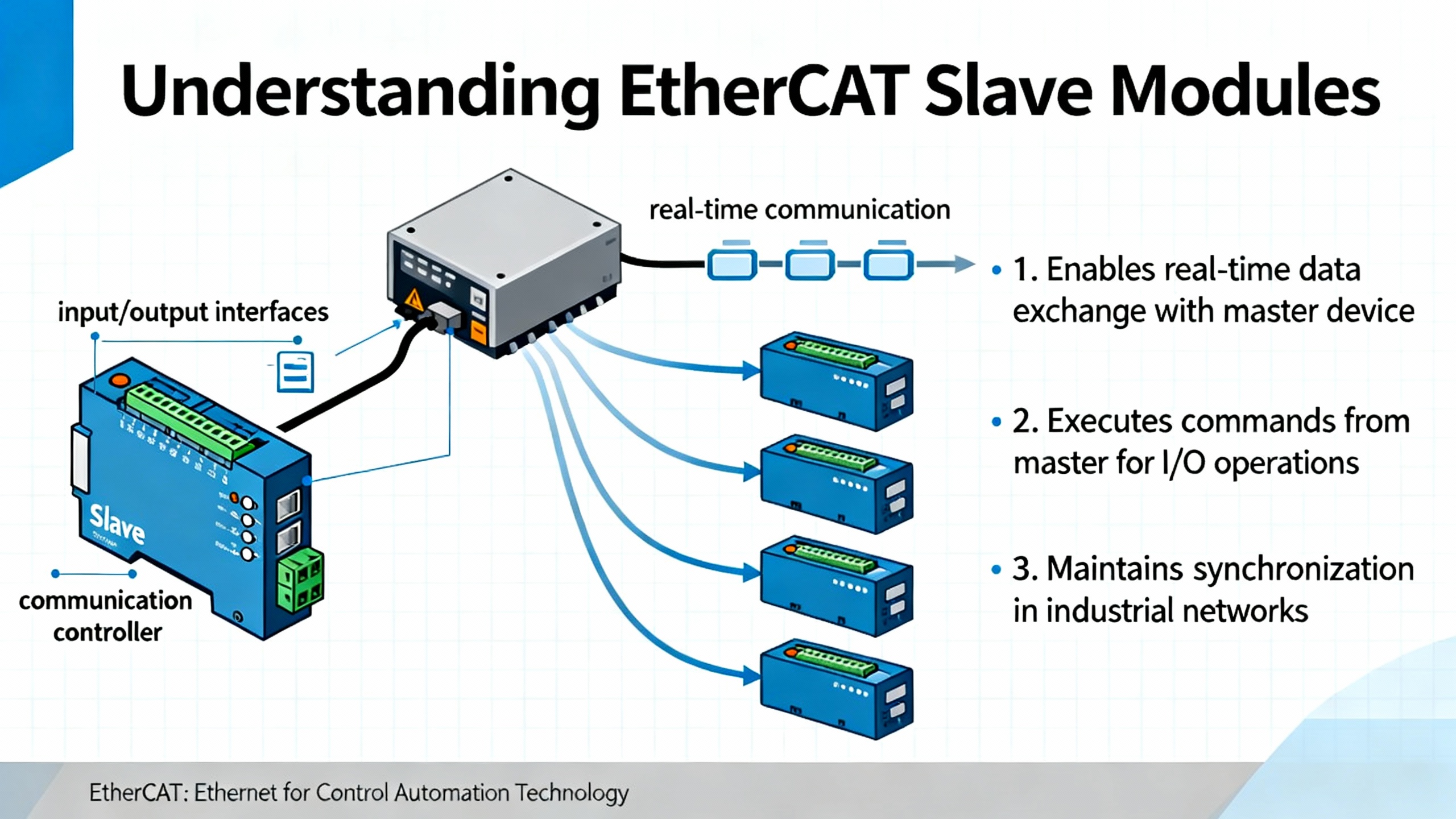
EtherCAT is a real‑time industrial Ethernet fieldbus standardized under IEC 61158. Rather than treating Ethernet like a mailbox where each node gets its own packet, EtherCAT has a single master send a frame that traverses every slave in a line or ring. Each EtherCAT slave reads its input data and writes its outputs on the fly as the frame passes through. The EtherCAT Slave Implementation Guide explains that this streaming approach enables cycle times down to well under a millisecond, with very high utilization of a 100 Mbit/s full‑duplex link.
An EtherCAT slave module is the field device that participates in this cycle. Inside, it consists of an EtherCAT Slave Controller, often called an ESC, plus an application processor or FPGA. The ESC terminates the Ethernet physical layer, parses EtherCAT telegrams, and exposes slave‑side memory and registers to the application. The EtherCAT Technology Group’s implementation guides describe how the ESC includes dedicated hardware for frame processing, Fieldbus Memory Management Units to map logical process data into memory, and SyncManagers to separate cyclic process data from mailbox traffic.
On top of that hardware sits a slave stack, such as Beckhoff’s ET9300 EtherCAT Slave Stack Code. ET9300 is a C‑based protocol stack that runs on a microcontroller or processor in combination with ESC chips like the ET1100 or ET1200. Application notes on ET9300 describe an architecture with an ESC access layer that abstracts the EtherCAT Slave Controller registers, an operating system and hardware abstraction layer that deals with timers and interrupts, and a protocol and application layer that manages process data and mailbox protocols such as CANopen over EtherCAT, File over EtherCAT, Servo over EtherCAT, and Ethernet over EtherCAT.
The application side of the slave sees all of this through the object dictionary. For CANopen over EtherCAT devices, that dictionary defines every parameter and every piece of process data the master can access. ET9300‑based workflows typically generate the dictionary and associated source code from EtherCAT Slave Information XML using Beckhoff’s dialog‑driven SSC Tool, keeping firmware and configuration in sync.
In parallel, the slave participates in the EtherCAT device state machine. The EtherCAT Slave Implementation Guide describes four main states: Init, Pre‑Operational, Safe‑Operational, and Operational. In Init, only very basic communication is possible. In Pre‑Operational, mailbox communication is enabled but cyclic process data is not. In Safe‑Operational, input data can be exchanged while outputs remain in a safe state, and in Operational both inputs and outputs are active. Well‑designed slave modules use state‑change callbacks to run hardware initialization, safety checks, configuration, and I/O mapping at predictable times.
From the system point of view, the slave dialogue with the master is split between cyclic Process Data Objects and acyclic Service Data Objects. National Instruments explains this clearly in its EtherCAT slave module tutorial: in their cRIO EtherCAT slave, the primary communication with the network runs through cyclic PDOs, while SDOs are used for configuration and diagnostics. That division of responsibility is a recurring theme in all robust EtherCAT slave designs.
Master‑centric, not peer‑to‑peer
It is important to emphasize that EtherCAT is strictly a single‑master, multi‑slave system. A technical explainer on slave‑to‑slave communication notes that the EtherCAT master is the only active sender of frames. Slaves are not general Ethernet nodes and cannot initiate communication on their own; they can only read or write data inside the frames created by the master.
Every EtherCAT Slave Controller contains a Fieldbus Memory Management Unit that maps a logical address space defined by the master into local memory, with bit‑level granularity. Clever use of this mapping allows what looks like slave‑to‑slave communication: one slave writes its data into a specific byte or bit of the process image, and another slave reads that byte or bit in the same cycle further down the line. The article points out that this still happens entirely under master supervision and within the standard EtherCAT frame, preserving timing determinism and keeping the architecture simple.
For high‑speed distributed control, that single‑master architecture is a strength. It avoids the complexity of multiple competing talkers, but it does mean your slave module cannot be treated like a fully independent Ethernet node. All design and debugging has to respect that constraint.
Why EtherCAT Slaves Fit High‑Speed Distributed Control
The EtherCAT Slave Implementation Guide summarizes EtherCAT’s performance motivation: a single real‑time frame traverses a chain of slaves, each slave manipulates its own data in the frame on the fly, and the frame returns to the master with updated information. Because the hardware does not need to buffer complete frames or contend for bus access, the system can achieve cycle times well below a millisecond while still using most of the nominal 100 Mbit/s bandwidth for process data.
Distributed Clocks, EtherCAT’s built‑in synchronization mechanism, reinforce this. According to EtherCAT Technology Group guidance, a DC‑capable network can align the clocks in slaves and master to sub‑microsecond precision, with jitter on the order of hundreds of nanoseconds. The DC hardware inside the ESC provides time stamps and synchronization events that the application can use to trigger sampling or actuation. An NI application note about the NI‑9144 EtherCAT expansion chassis states that these distributed FPGAs can execute custom timing and signal processing across multiple slaves while keeping them synchronized within about 100 nanoseconds.
That combination of deterministic cyclic communication and fine‑grained time synchronization fits the needs of high‑speed distributed control extremely well. Servo drives, high‑density I/O modules, and distributed data acquisition all benefit from being able to trust that data is updated in tight, predictable time windows, even when nodes sit hundreds of feet apart on a line topology.
From a practical perspective, EtherCAT slave modules also offer scalability and modularity. A configuration guide from Axel Software explains how ESI files describe slave capabilities and PDOs, while ENI network files represent the complete EtherCAT configuration for a master. When a master is configured correctly, it can scan the physical network, reconcile it with the ENI, and present channels to the PLC or motion kernel as simple variables. This is what allows vendors such as Omron, Beckhoff, and National Instruments to make EtherCAT the primary real‑time fieldbus for motion, safety, and distributed I/O in their flagship controller families.
This performance does come with trade‑offs. EtherCAT slave modules require disciplined engineering around the object dictionary, PDO mapping, and state machine behavior. The EtherCAT Slave Implementation Guide stresses that hardware interfaces must be sized for the intended cycle time, that mailbox and process data buffers must be dimensioned carefully, and that watchdogs and error handling must be implemented consistently. Field experience and vendor troubleshooting guides show that when these disciplines are not followed, you see hard‑to‑diagnose issues like slaves stuck in Safe‑Operational, missing inputs, or persistent working‑counter errors even though link LEDs are solid.
In other words, EtherCAT slave modules are a good fit for high‑speed distributed control as long as you are willing to design and maintain them like critical real‑time components, not generic Ethernet peripherals.
Inside a Modern EtherCAT Slave Module
Hardware platform and ESC
The EtherCAT Slave Implementation Guide recommends a reference architecture where a dedicated EtherCAT Slave Controller, whether as an ASIC or FPGA IP, is paired with an application microcontroller or FPGA. The ESC implements the Ethernet MAC layer, the EtherCAT frame parser, the FMMUs, and the SyncManagers. It also manages the line or ring topology through multiple ports and supports features like link detection and redundant rings.
Physical layer guidance from EtherCAT Technology Group focuses on standard 100BASE‑TX copper with line or ring topologies and cable segments of roughly 330 ft or less. The documents highlight correct PHY selection, link monitoring, and robust EMC and ESD design. For availability‑critical systems, they encourage designers to support ring and redundant topologies at the hardware level so the network can keep running even if a cable is broken.
An example of a highly integrated EtherCAT slave platform is the AX58400. According to the manufacturer’s description, this device combines an EtherCAT slave controller with two Ethernet PHYs and an embedded STM32H755 dual‑core microcontroller. The Cortex‑M7 core runs up to 480 MHz, and the Cortex‑M4 companion core runs up to 240 MHz. The platform also exposes a 10/100 Mbps Ethernet MAC interface over MII or RMII and includes USB, SPI, UART, and I2C interfaces for connecting sensors, actuators, or human‑machine interfaces.
The same platform integrates a JPEG accelerator for compressing and decompressing image data, which suits vision‑related applications, and hardware cryptographic accelerators for AES, TDES, HASH, and HMAC. On top of that, it offers security features such as read‑out protection, proprietary code read‑out protection, and anti‑tamper mechanisms. This blend of ESC, dual‑core processing, rich I/O, and security illustrates how modern EtherCAT slave modules can be complete embedded systems in their own right, not just simple interface cards.
Slave stack and configuration workflow
On the firmware side, Beckhoff’s ET9300 EtherCAT Slave Stack Code is a representative example of how a portable slave stack is structured. The ET9300 documentation describes an ESC access layer that hides details of the ET1100 or ET1200 register and memory model, an OS abstraction that normalizes timers, interrupts, and synchronization primitives, and a protocol layer that implements EtherCAT state machine handling, process data exchange, and mailbox protocols, including CANopen over EtherCAT, File over EtherCAT, Servo over EtherCAT, and Ethernet over EtherCAT.
A central element in this stack is the object dictionary. In ET9300 projects, the dictionary is typically generated from an EtherCAT Slave Information XML file using Beckhoff’s SSC Tool. That tool produces both the firmware structures and the master‑side XML, helping keep the ESI, firmware, and master configuration aligned. ET9300 documentation strongly advises against modifying core stack sources directly. Instead, hardware‑specific behavior is isolated behind well‑defined abstraction interfaces, and application‑specific logic is written against generated headers and APIs.
National Instruments provides another concrete look at configuration flows. In their CompactRIO EtherCAT slave module, a standalone PDO‑Configurator tool allows engineers to define variables, types, and directions for up to 1024 bytes each of transmit and receive PDO space. The configurator generates two outputs: an ESI XML file that describes the slave’s identity and PDO layout to EtherCAT masters, and a binary configuration file that the slave module itself consumes. The tool also encodes an eight‑digit identifier into both files, where the first part encodes a product identifier and the last part is a checksum of the PDO configuration. The slave uses that embedded code as its product identifier, and masters read it via SDO to confirm that the online device matches the configured profile.
This kind of configuration space and identity scheme is echoed in the EtherCAT Slave Implementation Guide. The ESC’s EEPROM and the ESI XML are expected to hold consistent information about vendor IDs, product codes, supported features, and default SyncManager and FMMU settings. EtherCAT Technology Group explicitly recommends using their validation tools to check that these descriptions are correct and self‑consistent before deploying devices to customers.
Process data, mailboxes, and drive mapping
At runtime, the slave’s job is to move data cleanly between EtherCAT frames and the application. For cyclic process data, that means configuring SyncManagers and FMMUs so that process‑data objects in the object dictionary appear at the correct logical addresses in the EtherCAT frame.
National Instruments notes that in the cRIO EtherCAT slave module, the PDO configurator captures variable names, data types such as Boolean and integer, and data direction from the network’s perspective. Transmit PDOs hold data sent by the master and received by the module, while receive PDOs hold data sent by the module and received by the master. The article further cautions that while changing array lengths alters the type, some EtherCAT master implementations, including National Instruments’ own EtherCAT master, do not support array types in PDOs and expect scalar elements. Decisions like this must be handled at design time rather than discovered late in commissioning.
Mailbox communication is handled separately. The EtherCAT Slave Implementation Guide recommends a clear separation between cyclic process data channels and mailbox channels, with dedicated SyncManagers and buffer sizing that can handle worst‑case CoE or FoE traffic. For drive applications, an ABB configuration note highlights that proper axis control requires mapping the drive’s object dictionary entries, such as control words, status words, target position, and actual position, into the cyclic PDOs in a way that aligns with the PLC’s axis control type. That object mapping step is what turns an EtherCAT slave from a pile of registers into a predictable motion axis in the PLC.
Time Synchronization with Distributed Clocks
Distributed Clocks are one of EtherCAT’s most powerful features for high‑speed control, but they are also a frequent source of confusion when wiring or topology is wrong.
An EtherCAT configuration guide explains that the first Distributed Clock‑capable slave in the main network is typically chosen as the reference clock. The master then aligns its internal time and tasks to that reference and uses distributed clock messages to keep all other slaves in lockstep. Configuration tools allow engineers to adjust synchronization shift times and divergence thresholds, but in a well‑designed network the default values are usually sufficient.
When the cabling is wrong, the symptoms can be subtle. The CODESYS EtherCAT troubleshooting documentation describes a diagnostic message indicating that the distributed clock value is always the same, with a recommendation to swap the in and out connectors of the relevant slave. In practice, this means that the device chosen as the time reference is not actually seeing proper frame traversal, so other devices cannot synchronize to it even though their network links appear healthy.
At the device level, EtherCAT Technology Group recommends that slaves which participate in tightly synchronized motion or measurement implement Distributed Clocks fully. Their implementation guide notes that typical systems achieve sub‑microsecond synchronization, with jitter around hundreds of nanoseconds, and that slaves can use Sync events from the ESC to trigger application tasks. The NI‑9144 expansion chassis example shows how this capability translates into practice: those distributed FPGAs can run custom timing and signal processing on separate chassis while remaining synchronized within about 100 nanoseconds of each other.
For high‑speed distributed control, the slave module needs to expose this time base correctly. That means wiring DC‑capable devices in the intended order, configuring the correct reference clock in the master, and designing the application so that sampling and actuation use Sync events rather than unsynchronized timers.

Engineering a Robust Slave Module
Designing an EtherCAT slave module for a high‑speed system is as much about fault behavior and maintainability as it is about nominal performance.
The EtherCAT Slave Implementation Guide devotes significant attention to the application‑layer state machine. It recommends that slaves implement watchdogs on link status, process data exchange, and application‑side processing. When a watchdog fires, the device should move to a defined safe state, typically by reverting outputs to safe values and transitioning to Safe‑Operational or Init, while signaling errors through Application Layer status and error codes. National Instruments extends this idea at the master level by mapping EtherCAT states into Scan Engine modes. In their terminology, Active mode corresponds to Operational, where real I/O is exchanged, while Configuration mode pauses network data updates and allows configuration changes such as adding slaves or updating firmware.
Configuration storage and identity are another cornerstone. EtherCAT Technology Group describes how ESC EEPROM holds identity information and default configurations. Masters read this information during network scans and compare it against what is described in the EtherCAT Slave Information XML. If vendor IDs, product codes, or revision numbers do not match, a well‑behaved master will warn the engineer or refuse to bring the device to Operational state until the discrepancy is resolved.
Performance design appears throughout the ETG guidance and Beckhoff’s ET9300 documentation. Both stress that the ESC‑to‑application interface must sustain the planned cycle time and process data size. This includes choosing a bus interface, such as parallel memory mapping or SPI, that can move data deterministically within the control cycle. It also means keeping cyclic processing paths short and non‑blocking. EtherCAT Technology Group explicitly advises designing for the target EtherCAT cycle time, which for many applications lies in the sub‑millisecond range, and minimizing application latency between ESC interrupts and I/O processing.
Security and intellectual property protection are increasingly important. As noted earlier, the AX58400 platform combines cryptographic accelerators with read‑out protection, proprietary code protection, and anti‑tamper mechanisms. For OEMs producing EtherCAT slaves that embed proprietary algorithms or safety functions, those hardware features help prevent unauthorized firmware extraction or modification. They do not remove the need for secure update and key management schemes, but they provide building blocks that are directly relevant to EtherCAT devices deployed in connected industrial environments.
Finally, conformance and interoperability are not optional in a high‑speed multi‑vendor network. EtherCAT Technology Group strongly recommends using the EtherCAT Conformance Test Tool throughout development. The implementation guide outlines test flows where engineers verify ESC register behavior, state‑machine transitions, mailbox services, Distributed Clocks, and error handling before taking a device to an accredited EtherCAT Test Center for official certification. Vendor documents, including those from Beckhoff and Hilscher, echo this emphasis and recommend wrapping EtherCAT‑specific APIs in a small abstraction layer in the application code so that updates to the slave stack or ESC do not ripple through the entire firmware.
In my own projects, devices that have gone through this conformance and abstraction discipline integrate cleanly with a wide range of masters and configuration tools. Devices that skipped these steps tend to produce late surprises in the test lab or, worse, in the field.
Diagnosing Slave Module Issues in Real Systems
Even with well‑designed hardware and firmware, EtherCAT slave modules are not immune to trouble. The difference between an acceptable and an unacceptable design is often how diagnosable it is when problems do occur.
An EtherCAT diagnostic guide for users highlights the Working Counter as a central concept. Each time a slave successfully processes a datagram, it increments the Working Counter. The master expects a specific value based on the number of slaves and the configuration. When the actual Working Counter is lower than expected, it indicates missing devices, unreachable segments, or processing errors. Alongside that, slaves expose port‑level error counters, such as CRC errors and lost link events. The guide recommends reading and trending these counters to localize issues along the line.
On the physical layer, the same document stresses basic but vital practices: using industrial‑grade shielded twisted‑pair cabling, respecting bending radii, keeping each copper segment to about 330 ft or less, and ensuring proper grounding and EMC practices. It also recommends designing the network for maintainability by labeling nodes and cables according to their logical EtherCAT position and documenting the topology, including branches and junctions. This makes it much easier to map diagnostic messages such as “network error between node 15 and 16” to a specific cabinet or conduit in the plant.
The CODESYS EtherCAT troubleshooting guide provides concrete examples of how these diagnostics surface in a real master. When the EtherCAT master logs that more than one hundred packets have been lost, it typically means communication between the PLC and the first slave has been interrupted. The recommended corrective actions are straightforward: reseat or replace the Ethernet cable, verify link LEDs on both devices, confirm that power supplies are stable, and, if problems persist, replace the suspect device.
Another diagnostic message from the same guide reports that the working counter for a synchronization group is wrong and the group is set to non‑operational. The root causes include slaves that have stopped communicating, unstable inter‑device cables, or power issues. CODESYS recommends checking network cables and link LEDs between devices, verifying power supplies to all slaves in the group, and swapping out misbehaving devices. A further warning that the number of slaves has changed or does not match the configuration indicates either that devices are missing or that the physical topology differs from what the master expects.
Distributed Clock issues, mentioned earlier, also show up in diagnostic logs. When the master reports that the distributed clock value is not changing, and suggests swapping the in and out connectors on a slave, it is pointing to a miswired segment that prevents proper time synchronization even though data may still be flowing.
National Instruments’ documentation on NI‑Industrial Communications for EtherCAT, along with their general troubleshooting practices, adds master‑side context. Their guidance emphasizes starting with hardware checks: confirming slave power, checking link and status LEDs, verifying cabling order from master ports to slave ports, and avoiding mixed networks where EtherCAT frames share unmanaged switches with general IT traffic. Configuration steps include rescanning the EtherCAT network, verifying that discovered slaves and products match the configured ESI descriptions, and updating or importing device descriptions for third‑party slaves.
A Chinese‑language case study from Solidotech illustrates how subtle the symptoms can be when a single slave misbehaves at the EtherCAT bus level. In that scenario, all devices, including an EtherCAT branch module and servo drives, reported Operational state in TwinCAT, and outputs worked correctly. However, every input channel at the PLC remained stuck at zero. Physical inspection showed that the input wiring and channel LEDs were healthy, and isolating the coupler into a small test network confirmed that it could upload inputs correctly. Only after systematically disconnecting slaves downstream of the branch module did the integrator identify a particular slave whose internal fault caused the entire bus input upload to fail while leaving outputs untouched.
The recommended approach in that case is a structured process: verify wiring and physical indicators, confirm that couplers and key slaves are not in special states that restrict input data, test suspect devices in isolation, and then use segment‑by‑segment disconnection to localize faults. Combined with monitoring of state words, error codes, and Working Counter behavior, this approach can reduce the time spent in blind trial‑and‑error debugging.
Finally, for systems that include programmable EtherCAT slaves, such as NI‑9144 chassis with user FPGA logic, the NI documentation notes that there is a limit to the number of user‑defined I/O variables that can be used to transfer data between the master’s real‑time application and the slave’s FPGA. They also point out that firmware updates may be required on slaves before custom FPGA code can run. Practical experience shows that being aware of such constraints early in design prevents late surprises when scaling up channel counts or deploying firmware updates in the field.
Design and Selection Tips for Slave Modules
When you are selecting or designing EtherCAT slave modules for a high‑speed distributed control project, it helps to tie the abstract guidance back to concrete criteria. The following table summarizes key design areas, the practical focus for each, and where the supporting guidance comes from.
| Design Area | Practical Focus in High‑Speed Systems | Supporting Guidance and Examples |
|---|---|---|
| ESC and physical layer | Proven ESC, robust PHYs, proper cabling and EMC, ring support where needed | EtherCAT Slave Implementation Guide and diagnosis user guide |
| Application platform | Sufficient CPU or FPGA headroom, clear split between real‑time and non‑RT | AX58400 platform description and NI‑9144 FPGA architecture |
| Stack and configuration | Portable slave stack, generated object dictionary, disciplined ESI/EEPROM | Beckhoff ET9300 documentation and ETG Slave Implementation Guide |
| Time synchronization | Full Distributed Clocks support, correct cabling and reference clock choice | EtherCAT configuration guidance and NI distributed FPGA examples |
| Diagnostics and testing | Working Counter, port counters, error codes exposed to HMI and logs | EtherCAT Diagnosis for Users and CODESYS and NI troubleshooting |
| Security and maintainence | Firmware protection, configuration management, conformance testing | AX58400 security features and ETG conformance test recommendations |
In practical terms, this means choosing slave modules whose datasheets and manuals clearly document their EtherCAT identity, object dictionary, Distributed Clock capabilities, and ESC details. It means insisting on ESI files that match shipped firmware versions, and on vendors who can demonstrate passing EtherCAT conformance tests. It also means designing your own application code, whether on a microcontroller or FPGA, to respect the EtherCAT cycle timing and state machine, and exposing enough diagnostics that your operations team can see more than just a generic “fieldbus error” alarm.
Frequently Asked Questions
How fast can an EtherCAT slave module update I/O?
EtherCAT Technology Group documentation describes systems where a single frame traverses all slaves in a line or ring, with each slave processing its data on the fly, enabling cycle times well below a millisecond and very high bus utilization on a 100 Mbit/s link. EtherCAT Slave Implementation Guides and ET9300 application notes both stress that the achievable cycle time depends on ESC choice, application‑side bus, CPU performance, and process data size. In practice, this means you should treat the cycle time stated in vendor documents as an engineering target and verify it under realistic load conditions with your actual master and network topology.
Do I really need Distributed Clocks on my slave modules?
If your application involves tightly coordinated motion, time‑aligned data acquisition, or distributed FPGA processing, the answer is effectively yes. EtherCAT documentation recommends implementing Distributed Clocks for devices that participate in such tasks and notes that typical systems achieve sub‑microsecond synchronization. The NI‑9144 example, where multiple FPGA‑equipped slaves run synchronized within about 100 nanoseconds, shows how this capability is used in real products. For simple on‑off I/O or low‑rate monitoring, you can sometimes operate without DC, but for high‑speed distributed control, it is one of the main reasons to choose EtherCAT in the first place.
How should I approach integrating third‑party EtherCAT slaves?
Vendor documentation from National Instruments, KEB, and others converges on the same pattern. Start by obtaining the EtherCAT Slave Information XML files from the device manufacturer and importing them into your master’s configuration tool so the devices appear correctly in catalogs. Use the master’s scan or auto‑discovery function to find connected slaves and verify that their vendor and product codes match the ESI descriptions. Then configure PDO mappings and axis or channel parameters according to the device documentation. If the slave does not reach Operational state, consult the master’s working‑counter and error logs and the slave’s Application Layer status codes. Finally, ensure that firmware versions and ESI files remain under configuration control so that later device revisions do not silently drift away from your tested configuration.
What is the most common design mistake in custom EtherCAT slave modules?
Based on the issues highlighted in the EtherCAT Slave Implementation Guide, Beckhoff’s ET9300 notes, and field troubleshooting cases, the most common mistake is underestimating the importance of a clean separation between the EtherCAT stack and application code. When application developers modify generated stack sources or mix slow non‑real‑time tasks into the EtherCAT cyclic path, they introduce timing jitter and make upgrades difficult. A close second is neglecting diagnostics and conformance testing: devices that do not implement Working Counter monitoring, meaningful error codes, and proper state transitions may appear to work in a lab with a single master and ideal wiring, but they tend to fail or misbehave in larger multi‑vendor networks.
Closing Thoughts
Reliable high‑speed distributed control systems are built not just on a fast fieldbus, but on disciplined EtherCAT slave modules that respect the protocol, expose clear diagnostics, and behave predictably under stress. The public guidance from EtherCAT Technology Group, Beckhoff, National Instruments, Omron, and other vendors gives you a solid blueprint. As a systems integrator and project partner, your job is to insist that every slave in your architecture follows that blueprint, from ESC and firmware all the way out to the HMI messages your technicians see at three in the morning.
References
- https://www.ethercat.org/download/documents/ETG2200_V3i1i1_G_R_SlaveImplementationGuide.pdf
- https://knowledge.gantner-instruments.com/q.stationx-ec-ethercat-slave-implementation-guide
- https://knowledge.ni.com/KnowledgeArticleDetails?id=kA03q000000YGrTCAW&l=en-US
- https://help.plc.abb.com/AB270_en/4be310e47f4e73e227d3f0c920701822_2_en_us.html
- https://www.solidotech.com/knowledge/troubleshooting-and-solutions-for-input-data-refresh-issues-in-ethercat-bus-network-devices
- https://www.axelsw.it/pwiki/index.php/Configuration:_EtherCAT
- https://www.come-star.com/blog/ethercat-slave-to-slave-communication/
- https://content.helpme-codesys.com/en/CODESYS%20EtherCAT/_ecat_troubleshooting.html
- https://www.kebamerica.com/blog/setup-guide-c6-ethercat-io-communication-with-a-beckhoff-plc/
- https://www.moxa.com/getmedia/76014bdb-dd28-42b2-a82d-b1d89f6ef4bc/moxa-building-a-fault-tolerant-ethercat-network-tech-note-v1.0.pdf
Keep your system in play!
Top Media Coverage
Categories


Related articles Browse All
-
 amikong NewsSchneider Electric HMIGTO5310: A Powerful Touchscreen Panel for Industrial Automation2025-08-11 16:24:25Overview of the Schneider Electric HMIGTO5310 The Schneider Electric HMIGTO5310 is a high-performance Magelis GTO touchscreen panel designed for industrial automation and infrastructure applications. With a 10.4" TFT LCD display and 640 x 480 VGA resolution, this HMI delivers crisp, clear visu...
 -
 BlogImplementing Vision Systems for Industrial Robots: Enhancing Precision and Automation2025-08-12 11:26:54Industrial robots gain powerful new abilities through vision systems. These systems give robots the sense of sight, so they can understand and react to what is around them. So, robots can perform complex tasks with greater accuracy and flexibility. Automation in manufacturing reaches a new level of ...
 -
 BlogOptimizing PM Schedules Data-Driven Approaches to Preventative Maintenance2025-08-21 18:08:33Moving away from fixed maintenance schedules is a significant operational shift. Companies now use data to guide their maintenance efforts. This change leads to greater efficiency and equipment reliability. The goal is to perform the right task at the right time, based on real information, not just ...


- Q&A
- Policies How to order Part status information Shipping Method Return Policy Warranty Policy Payment Terms
- Asset Recovery
- We Buy Your Equipment. Industry Cases Amikong News Technical Resources Why choose us
- ADDRESS
-
 32D UNITS,GUOMAO BUILDING,NO 388 HUBIN SOUTH ROAD,SIMING DISTRICT,XIAMEN
Leave Your Comment