
-
Please try to be as accurate as possible with your search.
-
We can quote you on 1000s of specialist parts, even if they are not listed on our website.
-
We can't find any results for “”.
Stepper Motor Controller 2‑Axis Synchronized Motion Control: A Field Guide from the Shop Floor
Why 2‑Axis Synchronized Motion Matters
When you move from single‑axis tinkering to real workpieces, you quickly discover that the hard problems are rarely about a single motor. They are about keeping two axes in lockstep while the machine carves, prints, cuts, or positions at the precision your process demands.
Two‑axis synchronized motion simply means that your X and Y axes move in a coordinated way along a defined path. Instead of “jog X, then jog Y,” you are asking the controller to trace a diagonal, a curve, or a complex contour where both axes start, accelerate, cruise, decelerate, and stop together. That is how CNC routers cut smooth arcs, how small gantry robots pick and place parts, and how dual‑axis trackers keep panels pointed at the sun.
In the field, I see the same patterns over and over. Teams underestimate wiring choices, power sizing, and control strategy, then blame the motors when things chatter or lose steps. The good news is this: with a solid understanding of stepper behavior, wiring topologies, and modern control firmware, a two‑axis stepper system can be boringly reliable. That is exactly what you want in an automation project.
Stepper Motors and Drivers: Foundations You Cannot Skip
What a Stepper Actually Gives You
A stepper motor is a brushless DC motor that moves in discrete angular steps. The controller sends pulses to the driver; the driver sends phased currents into the windings; the rotor snaps to a new magnetic equilibrium for each step. That is why steppers are ubiquitous in CNC machines, 3D printers, small gantries, and dual‑axis mechanisms: you get predictable position increments without encoders, as long as you stay within the motor’s torque envelope.
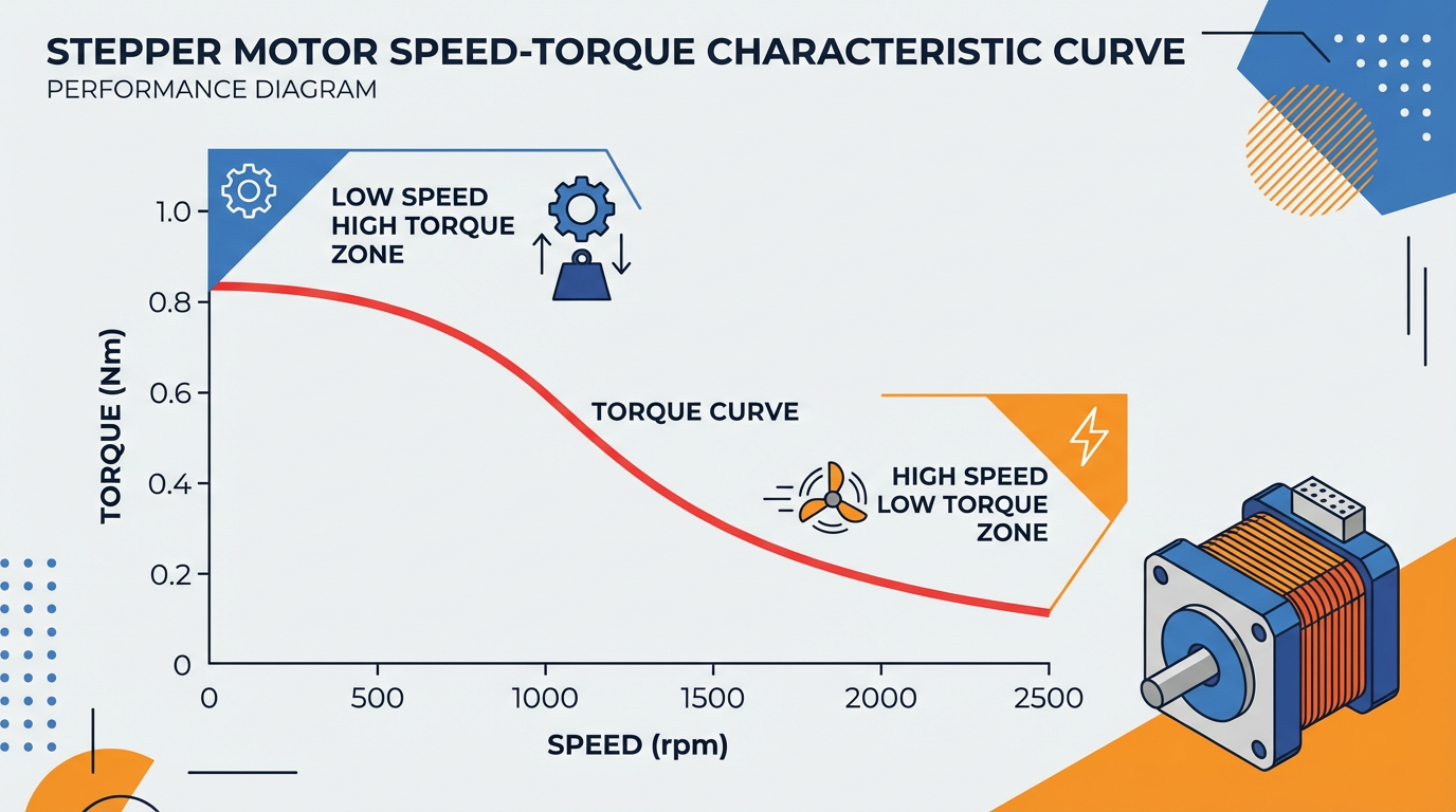
Torque in a stepper is essentially set by two ingredients: how much current you put into the phase, and how many turns of copper wire that phase has. As Oriental Motor explains, more turns give more holding and low‑speed torque, but also more inductance, which suffocates high‑speed torque. Fewer turns means less torque at low speed, but better ability to maintain torque as speed rises.
The speed–torque curve for a given motor–driver–voltage combination is your reality check. It tells you whether a motor can deliver the torque you need at the speeds your two‑axis move requires. Designing without looking at that curve is how you end up with a machine that jogs fine at low speed and then stalls the moment you try to cut at production feedrates.
Unipolar vs Bipolar: What the Labels Really Mean
Unipolar and bipolar originally described driver topologies. A unipolar driver sends current through each coil in only one direction; a bipolar driver can reverse current direction and work the same winding harder and more flexibly. In modern practice, people use unipolar or bipolar as shorthand for lead count and wiring options.
Six‑lead motors are often called unipolar, because each coil has a center tap. They can usually be wired as true unipolar or as bipolar‑series by ignoring the center taps. Four‑lead motors are permanently wired as bipolar internally and can only be driven that way. Eight‑lead motors are the most flexible; you can wire their coils in unipolar, bipolar‑series, or bipolar‑parallel configurations.
The choice of wiring has direct consequences. Using only half of each coil (half‑coil, from center tap to one end) reduces the number of turns and the inductance, which slightly lowers torque but helps sustain torque at higher speeds. Using the full coil in series increases torque but also increases inductance significantly, so torque falls off quickly as you increase speed. Bipolar‑parallel uses the full coil but splits it into parallel branches, delivering high torque and high‑speed performance at the cost of higher phase current.
From an integrator’s standpoint, the pattern is clear. When driver current capacity allows it, bipolar‑parallel is usually the sweet spot for high‑performance motion. When you are current‑limited but can afford to lose some high‑speed torque, bipolar‑series can be acceptable.
Multi‑Lead Motors and Coil Identification
Real‑world machines arrive with motors whose datasheets have been lost. Buildbotics and other controller vendors take a very pragmatic approach here: find coil pairs with an ohmmeter. For a four‑wire motor, any two wires that show a few ohms of resistance belong to the same coil; the remaining two form the other coil. Assign one pair to driver terminals A+ and A‑, the other to B+ and B‑. If the shaft turns the wrong way, swap the plus and minus on one coil pair.
For six‑wire motors, you first group wires into coils using resistance measurements. The center tap will show about half the resistance to each end, and the two ends will show about twice that value between them. In bipolar‑series wiring for a modern CNC controller, you leave the center taps unconnected and wire only the ends to A+ / A‑ and B+ / B‑.
Eight‑wire motors are powerful and dangerous in equal measure when miswired. The safe approach is to obtain the manufacturer’s lead map and wire for either bipolar‑series or bipolar‑parallel as recommended. Because the number of possible combinations is large, Buildbotics explicitly recommends avoiding trial‑and‑error with an ohmmeter for eight‑lead motors unless you have no alternative.
One hard rule surfaces again and again in controller documentation: five‑wire steppers are strictly unipolar and cannot be wired as bipolar motors. If your two‑axis controller requires bipolar motors, a five‑wire stepper is simply the wrong component.
Real‑World 2‑Axis Architectures
Classic X–Y with One Motor per Axis
A straightforward two‑axis layout has one motor on X and one on Y, each with its own driver channel. An Arduino‑based project using a Quadstepper driver and two salvaged scanner mechanisms shows how effective this simple architecture can be. The author stripped two flatbed scanners down to their rails, belts, and MOTOTECH stepper motors, then drove both axes from an Arduino UNO and a quad‑channel bipolar driver. The salvaged motors were unipolar units, but by ignoring the common wire and using the remaining leads, they were driven as bipolar motors.
With careful wiring and mechanical reuse, that project achieved an estimated step size of about 0.002 in per step. It is a good illustration of how much precision you can get out of inexpensive, recycled hardware when the wiring and drive strategy are sound.
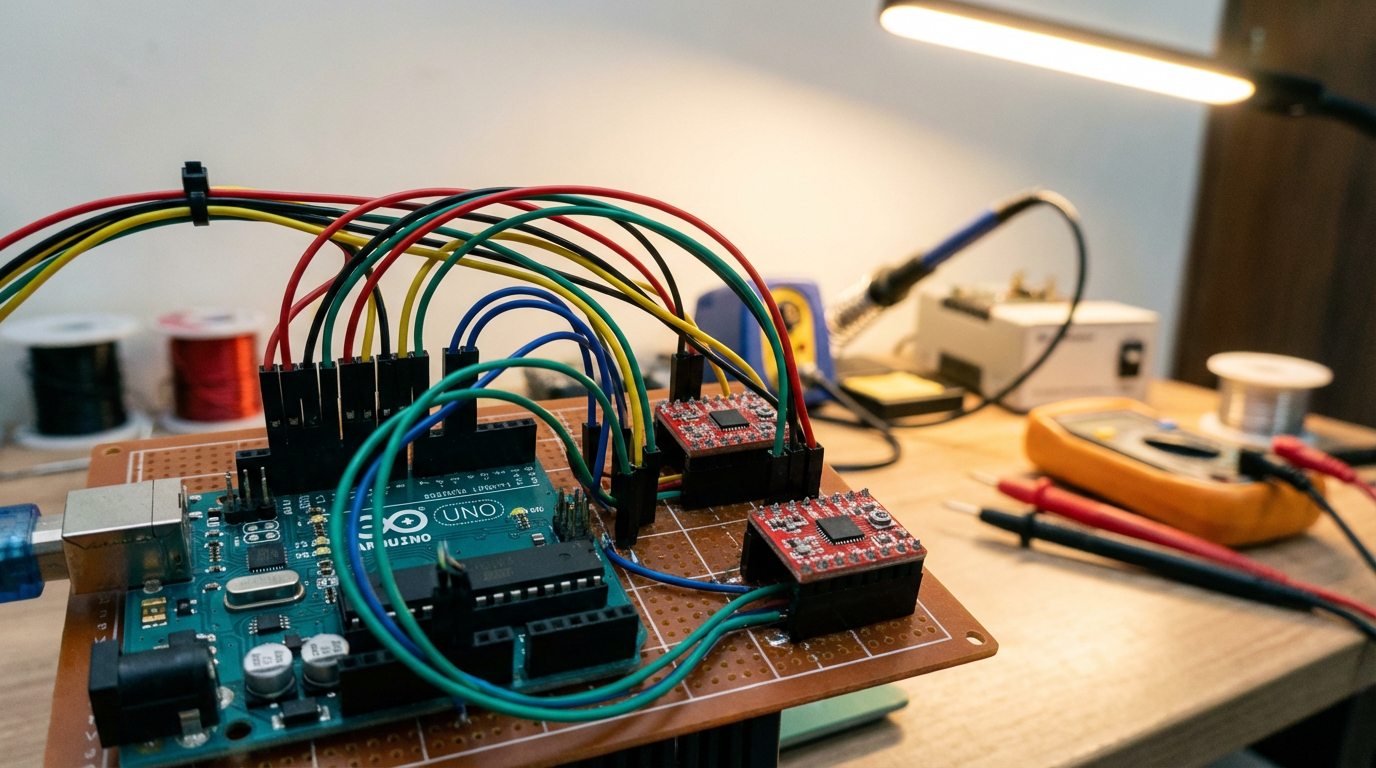
Another instructive example is a portable two‑axis stepper controller that drives a pair of small 28BYJ‑48 steppers from an Arduino and ULN2003 driver boards. Here the author powers both motors and the Arduino from a single well‑regulated 5 V supply, feeding the Arduino’s 5 V pin directly rather than the Vin pin. Each motor draws about 240 mA and the Arduino plus display about 100 mA, so the total draw is a little over 500 mA. The designer explicitly warns against powering this full system from a PC USB port; instead, they use a dedicated 5 V supply rated comfortably above that current and add a 100 µF capacitor across the rails to smooth transient dips when the motors step.
What these examples demonstrate is that a modest microcontroller can comfortably manage two axes, as long as the electrical design is deliberate and the current paths and supply margins are understood.
Dual Motors on One Axis, Still Two Axes Logically
Many gantry machines, especially routers and lasers, use two motors to drive a single axis, typically the Y axis, while X and Z each have one motor. It is still a two‑axis or three‑axis machine logically, but there may be three or four physical stepper motors. The controller has to keep the two motors on the shared axis synchronized so the gantry does not rack or twist.
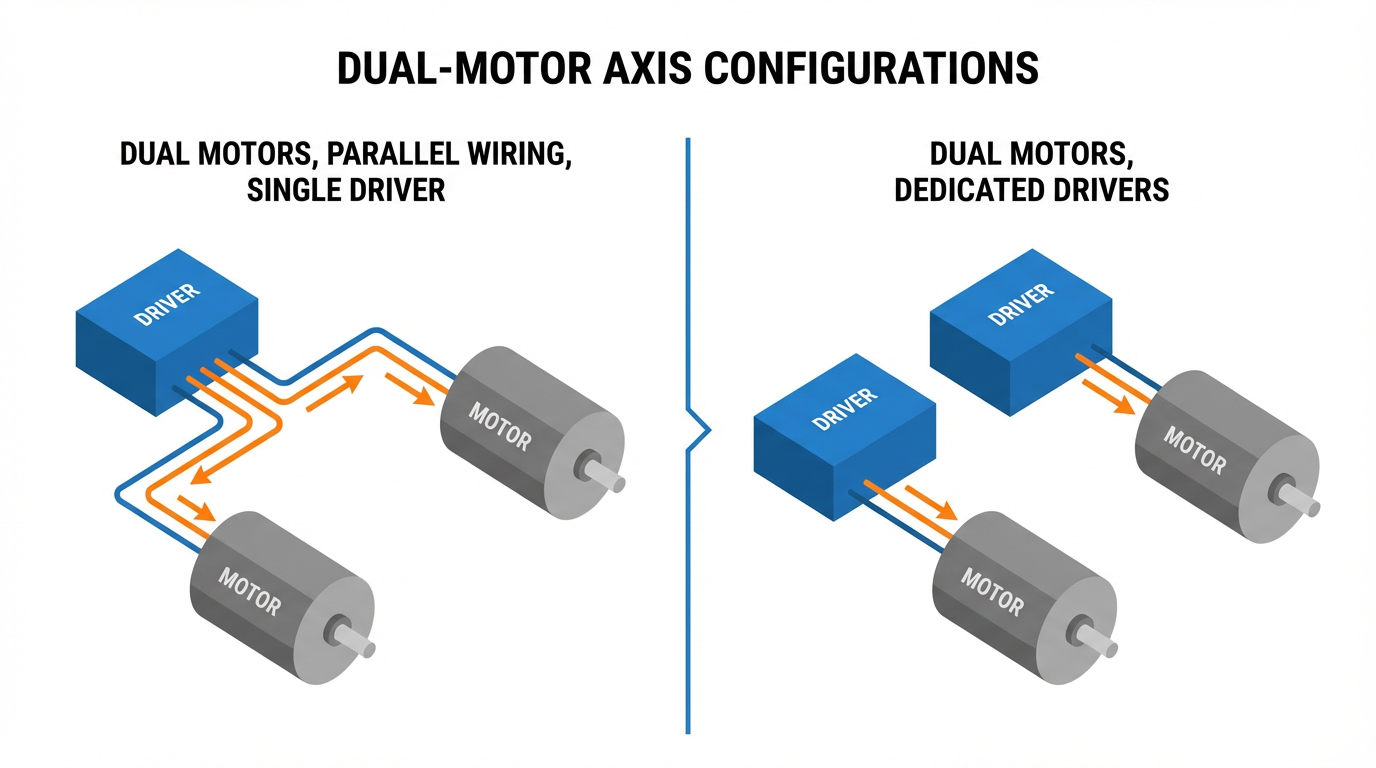
Controllers derived from the Buildbotics architecture, including the Onefinity CNC controller, allow either wiring two motors in parallel on a single driver output or assigning two separate outputs to the same axis. Each output can supply up to 6 A peak per coil. Because both coils are driven with sine‑like currents that are ninety degrees out of phase, Buildbotics notes that the peak instantaneous current on a single motor output can reach about 8.48 A, with total average motor current across all axes limited to about 10 A.
If you put two motors on a single output in parallel, the required driver current setting is essentially the sum of the individual motor current ratings. Two 2.8 A motors wired in parallel require a 5.6 A current limit; that fits under the 6 A ceiling. Two 3.5 A motors clearly do not. Buildbotics therefore cautions that you cannot put two motors rated above roughly 3 A each on the same port.
In practice, these controllers recommend wiring dual motors on one port in parallel rather than series, to keep high‑speed performance acceptable, while warning that parallel‑wired motors can mechanically and electrically resonate with each other. Stalls at certain speeds are common; they have to be found experimentally on the actual machine.
Where the controller has spare motor outputs, the cleaner solution is to assign each motor on the shared axis to its own driver, then configure both outputs as the same axis in firmware. That approach avoids driver current limits and reduces resonance coupling between motors. LightBurn’s community around the DLC32 Max board echoes the same theme: use two identical external stepper drivers, both fed from the same step and direction signals, and avoid mixing an onboard driver with a dissimilar external driver on the same axis.
On the firmware side, communities around grblHAL stress that axis “slaving” should be done in software, not by trying to stack or parallel the outputs of two drivers electrically. Modern 32‑bit boards make it easy to copy one axis’s step and direction signals to another set of pins, while classic 8‑bit GRBL boards are far less flexible. Contributors on MakerForums are blunt about this: you cannot safely “just stack” driver outputs to clone an axis; let the firmware provide axis slaving on a capable controller.
Finally, on small machines and 3D printers, people often wire dual Z motors in parallel to a single driver. A practitioner who runs dual Z steppers this way reports that they deliberately use robust CNC‑style drivers rated around 3 A, mounted on generous heatsinks, rather than tiny plug‑in modules. The message is straightforward. If you insist on one driver per two motors, the driver must be sized and cooled for the combined current.
Achieving True Synchronized Motion Between X and Y
Let the Motion Controller Do the Hard Work
When you need a precise XY path over time, the temptation is to calculate step pulses directly. On the Arduino forums, a user working with a table of time, X, and Y coordinates asked how to drive two steppers simultaneously to follow that path. Experienced members pointed out an easier route: treat the data as standard CNC moves and let a motion controller such as Grbl handle the step timing.
They converted each segment between two points into a G‑code line. G‑code does not encode time directly; it specifies target coordinates and a feedrate. If a move from one point to the next covers about 0.56 in diagonally and is supposed to take 1.2 seconds, you compute a linear speed of roughly 0.47 in per second, which corresponds to about 28 in per minute, and use that as the feedrate value. A command such as G1 X… Y… F28 then expresses the desired motion. Grbl, running on an Arduino‑class controller, takes those G‑code lines, plans a motion profile, and generates properly synchronized step pulses for the X and Y drivers.
In the field, this separation of concerns is critical. The upstream software or script computes the path and per‑segment feedrates; the firmware on the controller handles acceleration ramps, jerk limits, and axis synchronization. You get two‑axis coordinated motion with well‑tested firmware instead of bespoke timing code that you have to validate yourself.
Manual Two‑Axis Control with Joysticks
Not every system is CNC‑like. One Arduino forum thread describes a beginner who wanted purely manual two‑axis control of larger stepper motors using an Arduino, a joystick, and four limit switches. The requirement was simple at a glance: push the joystick left, right, up, or down, and have the two axes move proportionally, with smooth acceleration and deceleration, and with limit switches protecting both ends of travel.
The question was whether a single Arduino could manage both axes, the joystick, and four limit switches while still providing motion ramping. Community feedback indicated that it is feasible on a single board if the code is structured properly and uses a suitable stepper library. The real challenge is not raw CPU power but writing motion code that enforces acceleration limits and never blocks while reading inputs.
From an integrator’s perspective, this tells you that simple, human‑in‑the‑loop two‑axis control is not fundamentally different from automated control in its demands on the driver and motors. You still need to respect speed–torque limits, avoid instant full‑speed starts, and wire limit switches in a way that guarantees the machine will stop before hitting the hard stops.
Controller Choices for 2‑Axis Stepper Systems
Arduino and Grbl‑Style Platforms
Arduino‑class boards are more than capable of driving two axes when paired with suitable drivers. The Instructables project using an Arduino UNO, a SparkFun Quadstepper, and salvaged scanner mechanics is a textbook example: one board, one driver module, and two axes of reasonably precise motion for very modest cost.
A separate portable two‑axis controller example shows a different style. Here, a small Arduino and two ULN2003 driver boards drive low‑power 28BYJ‑48 steppers. The design emphasizes power integrity and reusability rather than raw torque. Power is provided by a single regulated 5 V source, carefully kept below about 5.5 V. All motor and controller grounds are tied together on a perfboard, with headers and short jumpers making it easy to plug and unplug motors, buttons, and a display. A 100 µF electrolytic capacitor is placed close to the supply rails on the perfboard to absorb brief current spikes.
Both designs use perfboard and headers to keep wiring maintainable. Cables for motors and front‑panel controls are soldered from the front of the perfboard and linked to headers via solder bridges on the back, producing a layout that is easy to inspect and modify. From an integration standpoint, those are not cosmetic details. When you revisit a control box months later to troubleshoot a missed‑step issue, having an organized wiring layout saves hours.
Offline CNC Controllers and Industrial Practices
For heavier machines, hobby‑grade shields quickly run out of runway. One builder documented replacing a PC‑and‑USB Mach3 setup on a mid‑size router with an offline DDCS4 controller in a new enclosure. They reused a 2.2 kW VFD and a 40 V, 10 A DC supply for four NEMA 23 steppers, supplemented with separate 24 V supplies for logic and IO and a DC‑DC converter for 12 V auxiliaries.
A key observation from that build is power sizing. Four 3 A motors might suggest a 12 A supply, but the builder cites the common rule of thumb that you can often size the DC supply at about two‑thirds of the sum of the motor phase currents. The 10 A supply worked acceptably in practice, because not all motors draw peak current simultaneously under realistic loads. For typical NEMA 23 motors, they recommend supply voltages in the 24 to 48 V range, with 48 V providing better torque at higher speeds.
Equally important is safety. Instead of simple in‑line mains switches, the builder uses an industrial contactor controlled by momentary on and off pushbuttons and an emergency stop. The contactor latches using its auxiliary contacts and drops out on off, on E‑stop, or on power failure. The machine therefore cannot restart automatically when power returns, which is a baseline requirement in any serious industrial environment. They back up the DDCS controller’s software E‑stop with a hard‑wired E‑stop that physically opens the contactor circuit feeding the stepper drivers and the VFD.
Noise and grounding also receive attention. The VFD is fed through an EMI filter and a ferrite ring on the mains side and ideally housed in its own metal enclosure to reduce interference. Stepper motor cables are shielded both inside and outside the cabinet, and when those cables pass through metal circular connectors, the cable shield is folded back to contact the connector shell and grounded via the metal mounting plate. That avoids stray ground wires and keeps the high‑frequency return paths short and predictable.
These practices might feel like overkill for a small two‑axis system, but in reality they are what separate prototypes from production equipment.
Modern 32‑Bit Boards and Axis Slaving
The GRBL ecosystem has evolved. Classic 8‑bit boards have limited IO and configuration options; by contrast, newer 32‑bit platforms running firmware such as grblHAL or FluidNC can natively support dual‑motor axes with per‑motor homing and electronic squaring.
Community discussions around these platforms converge on a common recommendation. If you need two motors on one axis, do not try to hack the hardware by stacking driver outputs or bodging traces. Instead, choose a controller that can output separate step and direction signals for each motor and define them as slaved axes in firmware. Modern 32‑bit boards are inexpensive compared to the cost of a machine, and they give you cleaner axis slaving, better motion planning, and a more sustainable path for future features.
Wiring and Power: Where Two‑Axis Projects Usually Fail
Correct Coil Wiring and Direction Control
Most driver manufacturers provide clear terminal labeling, but fielded machines often arrive with unlabelled cables. The Buildbotics documentation lays out a simple method: identify coil pairs with an ohmmeter, connect one pair to driver terminals A+ and A‑, the other pair to B+ and B‑, and test. If the motor spins in the wrong direction during jogging, reverse the polarity of one coil by swapping A+ and A‑ or B+ and B‑. Never reverse both pairs; that simply restores the original direction.
For applications where two motors must move in opposite mechanical directions on the same driver channel, such as gantry sides facing each other, you deliberately reverse one coil on one motor. Both motors receive the same step and direction signals; one motor’s wiring makes its shaft turn clockwise while the other turns counterclockwise. A short, practical note from a CNC discussion group explains exactly this trick: wire both motors in parallel on the Y output, then invert one coil on one motor so they move in opposite directions while staying synchronized.
Series vs Parallel When Sharing a Driver
When you hang two motors off one driver, you have three intertwined decisions: series or parallel wiring, the driver’s current rating, and your performance target.
In series wiring, both motors share the same phase current, but the required voltage rises because you are effectively adding the motor windings together. This can soften the load on the driver’s current rating but limits high‑speed torque because of higher combined inductance. In parallel wiring, each motor sees the same voltage, and step response is better because the effective inductance seen by the driver is closer to that of a single motor. The downside is that the driver must supply roughly the sum of the currents of both motors.
Real‑world experiences back the theory. On CNC routers using Buildbotics‑class controllers, parallel wiring is generally recommended for dual motors on one port, provided the sum of the motor currents remains within the 6 A per‑port limit. On a 3D printer with dual Z steppers wired in parallel, a user reports using robust 3 A‑class drivers on large heatsinks to keep temperatures under control.
If parallel wiring would force you beyond the driver’s safe current limit, the options are to move to one driver per motor or accept the speed limitations of series wiring. Trying to squeeze two high‑current motors into one undersized driver is not frugal; it is an engineered failure that will show up as overheated drivers, skipped steps, or emergency shutdowns.
Power Supply Sizing and Protection
Power supplies are another recurring weak point. The offline controller retrofit mentioned earlier used a 40 V, 10 A supply for four 3 A NEMA 23 motors. That works because stepper drivers regulate current to the motors and the motors rarely all draw peak current simultaneously. The commonly cited guideline of sizing the PSU at about two‑thirds of the sum of the motor phase currents holds up well here.
On the low‑voltage end, the portable two‑axis Arduino controller shows how to safely run both motors and logic from one 5 V source. The key conditions are that the supply is truly regulated, its voltage stays below roughly 5.5 V, and its current rating is comfortably above the combined draw of motors, controller, and display. The designer prohibits running the motors from USB power and adopts a disciplined procedure: disconnect the external supply during programming over USB, then reconnect it only after the code is loaded and USB is unplugged.
Regardless of voltage level, bulk capacitance placed near the drivers helps buffer current spikes and reduces the chances of brown‑out resets on the logic side. For mains‑fed enclosures, selecting properly rated inlet connectors and fuses is non‑negotiable. For example, common C14 inlets are typically rated around 10 A at 250 V; if your VFD and stepper supply combination can draw more or if you expect high inrush currents, a fixed cable with an internal fuse or a higher‑rated plug standard is more appropriate.
Noise, Shielding, and Grounding
Two‑axis motion means more cable runs, more switching edges, and more opportunities for electromagnetic interference to bite you. Field experience and documented builds align on a few practices.
First, use shielded cables for stepper motors both inside and outside the cabinet. Terminate the shields properly by wrapping them back over the cable jacket where they pass through metal circular connectors so the shield makes solid contact with the connector shell and, through that, with the metal enclosure. This approach makes the enclosure your reference for high‑frequency returns without cluttering the panel with extra ground wires.
Second, treat VFDs as noisy neighbors. An EMI filter on the VFD’s mains input, a ferrite or two on its leads, and a separate metal enclosure for the VFD where practical all help keep its switching noise from coupling into your step and direction lines.
Third, keep logic power and IO power reasonably separate where the controller allows it, as the DDCS controller does with separate 24 V supplies. That reduces the loop area in which noise can couple into sensitive logic, and makes it easier to debug issues by isolating subsystems.
Motion Profiles, Limits, and Safety
Acceleration and Deceleration
Even at modest feedrates, a two‑axis move that starts and stops abruptly is a recipe for missed steps and vibration. The Arduino user who wanted smooth joystick‑driven motion for two axes instinctively understood this and specifically asked for ramped acceleration and deceleration.
Whether the system is manual or G‑code driven, the constraint is the same. The controller should never demand instantaneous full speed from a stepper; it should ramp up and ramp down within the boundaries imposed by the speed–torque curve and the mechanical inertia of the axis. Grbl and other mature motion controllers handle this internally. When you are hand‑coding motion on a microcontroller, you have to implement an equivalent ramping strategy yourself or use a library that does so.
For dual‑motor axes, this becomes even more important. If one side of a gantry stalls due to aggressive acceleration while the other keeps moving, the gantry binds and the resulting mechanical stress can misalign rails or belts.
Limit Switches and Homing
Two axes mean at least four travel extremes to manage. In the Arduino joystick control example, the user specified four limit switches, implying minimum and maximum switches for each axis. That is a sound pattern: one switch to prevent overruns at each end of each axis, wired so that a switch failure is detectable.
On multi‑motor axes, modern firmware such as grblHAL can use separate limit switches for each side of a gantry to perform independent homing and automatically square the axis. Hardware support for that kind of per‑motor limit input is one of the quiet advantages of moving to 32‑bit controller platforms.
Even on simpler systems, it pays to think through what happens when a limit switch opens. Does it simply signal the firmware, or does it also open a safety circuit that cuts power to the drivers if the controller fails to react? For anything beyond a desktop prototype, I favor wiring limit circuits so that they fail safe: a broken wire or failed switch should stop motion, not allow unbounded travel.
Emergency Stops and Power Interlocks
A properly designed E‑stop is not optional on moving machinery. The DDCS‑based controller build demonstrates a layered approach that aligns with how industrial systems are built. The controller has a software E‑stop input that immediately halts motor and spindle commands and requires a reset before motion can resume. In addition, a physical E‑stop button wired in series with the contactor’s control circuit drops out power to the drivers and the VFD.
The use of a latching contactor means that after an E‑stop or power failure, the machine remains de‑energized until an operator deliberately presses the start button. This prevents a recovered controller from suddenly energizing axes that may be partially disassembled or obstructed.
For a two‑axis bench‑top system, it may feel tempting to omit such circuitry and rely on unplugging a power brick. My view, informed by too many hours in cramped cabinets, is that once a system can move fast enough to hurt fingers or ruin parts, it deserves a real E‑stop and a predictable power‑up sequence.
Pros and Cons of 2‑Axis Stepper Synchronized Control
A two‑axis stepper system offers a compelling balance of simplicity, cost, and precision. You can repurpose scanner mechanics, use affordable NEMA 23 drives, and run everything from an Arduino‑class board or a compact offline controller. Proper wiring and configuration give you smooth XY motion for cutting, marking, or positioning tasks without the complexity of encoders or servo tuning.
The trade‑offs emerge at the edges. Torque falls off as speed increases, especially with high‑inductance or series‑wired motors. Parallel wiring of dual motors can unlock better performance but demands drivers with higher current ratings and more serious cooling, as machine builders and 3D printer users have reported. Running two motors from one driver increases the risk of resonance and the consequences of a stall, so the mechanical design and acceleration profiles have to be conservative.
Firmware capabilities matter as well. Older controllers may handle simple two‑axis moves but struggle with dual‑motor axes, per‑side homing, or advanced path planning. Modern 32‑bit controllers running firmware like Grbl derivatives or grblHAL offer more flexibility and safety features at relatively low incremental cost.
What does not change with controller choice is the need for disciplined electrical and mechanical design: appropriate supply sizing, careful shielding and grounding, proper limit and E‑stop wiring, and a realistic reading of the motor’s speed–torque curve.
Wiring Modes at a Glance
For quick comparison, here is how common wiring modes behave in practice, drawing on stepper wiring guidance from Oriental Motor and multi‑motor usage notes from Buildbotics and others.
| Wiring mode | Typical lead support | Current demand on driver | Torque behavior | High‑speed behavior | Notes for 2‑axis systems |
|---|---|---|---|---|---|
| Unipolar | 5‑ or 6‑lead center‑tapped | Moderate | Decent holding, modest overall torque | Drops off relatively early | Simpler drivers; less common in modern CNC controllers |
| Bipolar half‑coil | 6‑lead, using half coils | Lower than full bipolar | Lower holding torque | Better than full‑coil at higher speeds | Useful when driver current is limited |
| Bipolar‑series | 6‑ or 8‑lead in series | Lower than parallel for same motor torque | Higher low‑speed torque | Torque falls quickly as speed rises | Works when supply voltage is high but driver current is tight |
| Bipolar‑parallel | 8‑lead, full coils in parallel | Highest among the options | High holding and running torque | Best high‑speed torque retention | Preferred when drivers can deliver the needed current |
| Two motors parallel | Any bipolar, motors in parallel on one driver | Sum of both motor currents | Comparable torque per motor at low speed | Sensitive to resonance; driver heavily loaded | Only within driver current limits; best with identical motors and robust drivers |
In practice, for a two‑axis machine that must move briskly and reliably, I gravitate toward bipolar‑parallel on each motor with one driver per motor, then use firmware axis slaving where necessary. Only when hardware or budget constraints force it do I accept two motors on one driver, and then only after checking current limits, testing for resonance, and providing generous cooling.
FAQ
Can one driver safely run two stepper motors on a single axis?
Yes, but only within strict boundaries. Documentation from Buildbotics and experiences shared by Onefinity CNC users show that two motors can be wired in parallel to one driver output when the sum of the motor currents stays within the driver’s rated per‑coil current, and when the total average current across all axes stays within the controller’s global limit. For example, two roughly 2.8 A motors on a port rated for 6 A can be acceptable; two high‑current motors that would push the port beyond its rating are not. Even when the numbers work, you still need to verify by experiment that the dual‑motor system does not hit resonance zones and stall at certain speeds.
Is series or parallel wiring better for dual motors on one output?
Parallel wiring generally gives better overall performance. Each motor sees the full supply voltage and can maintain torque farther up the speed range. The price is that the driver current setting must match the sum of both motor currents, which demands a driver with sufficient headroom and cooling. Series wiring can work when driver current is tight and the supply voltage is high enough, but the combined inductance of the two motors in series causes torque to fall off rapidly as speed increases. For most practical two‑axis CNC or gantry systems, parallel wiring paired with a properly sized driver is the more robust choice.
Is a single Arduino enough to run two synchronized axes with a joystick and limit switches?
Community examples suggest that it is, provided the design is sensible. One Arduino forum thread describes exactly that scenario: two steppers, a joystick, and four limit switches, with a requirement for smooth acceleration and deceleration. The consensus was that a single Arduino can handle it if you write non‑blocking motion code or use a proven stepper library, and if you design the power distribution correctly. For more complex profiles or higher performance, running Grbl on an Arduino and generating G‑code externally is often a cleaner path, because the firmware already knows how to synchronize the two axes and handle acceleration.
Closing
Two‑axis synchronized motion with stepper motors is not black magic; it is a stack of practical decisions about wiring, power, firmware, and safety. When those decisions are made carefully, a two‑axis system will run day in and day out without drama. As someone who has spent plenty of time inside control cabinets fixing avoidable mistakes, my advice is simple: respect the speed–torque curve, size drivers and supplies honestly, and let well‑tested motion firmware do the heavy lifting of synchronization. If you build on those foundations, your two‑axis stepper controller will behave like a reliable project partner, not a science experiment.
References
- https://www.academia.edu/92859750/Dual_axis_solar_tracker_system_using_optimal_hybrid_controller
- https://digitalcommons.cwu.edu/cgi/viewcontent.cgi?article=1012&context=undergrad_hontheses
- https://smartgridlab.seas.gwu.edu/files/2020/08/C28.pdf
- https://admisiones.unicah.edu/scholarship/zKOEFm/9OK166/ManualStepperMotorController.pdf
- https://forums.adafruit.com/viewtopic.php?t=156463
- https://blog.orientalmotor.com/stepper-motor-wiring-basics-unipolar-vs-bipolar
- https://buildbotics.com/wiring-stepper-motors/
- https://www.instructables.com/Arduino-Portable-Two-Axis-Stepper-Control/
- https://forum.arduino.cc/t/2-axis-stepper-motor-control/654445
- https://www.cnczone.com/forums/stepper-motors-drives/112753-cnc-software-forum.html
Keep your system in play!
Top Media Coverage
Categories


Related articles Browse All
-
 amikong NewsSchneider Electric HMIGTO5310: A Powerful Touchscreen Panel for Industrial Automation2025-08-11 16:24:25Overview of the Schneider Electric HMIGTO5310 The Schneider Electric HMIGTO5310 is a high-performance Magelis GTO touchscreen panel designed for industrial automation and infrastructure applications. With a 10.4" TFT LCD display and 640 x 480 VGA resolution, this HMI delivers crisp, clear visu...
 -
 BlogImplementing Vision Systems for Industrial Robots: Enhancing Precision and Automation2025-08-12 11:26:54Industrial robots gain powerful new abilities through vision systems. These systems give robots the sense of sight, so they can understand and react to what is around them. So, robots can perform complex tasks with greater accuracy and flexibility. Automation in manufacturing reaches a new level of ...
 -
 BlogOptimizing PM Schedules Data-Driven Approaches to Preventative Maintenance2025-08-21 18:08:33Moving away from fixed maintenance schedules is a significant operational shift. Companies now use data to guide their maintenance efforts. This change leads to greater efficiency and equipment reliability. The goal is to perform the right task at the right time, based on real information, not just ...


- Q&A
- Policies How to order Part status information Shipping Method Return Policy Warranty Policy Payment Terms
- Asset Recovery
- We Buy Your Equipment. Industry Cases Amikong News Technical Resources Why choose us
- ADDRESS
-
 32D UNITS,GUOMAO BUILDING,NO 388 HUBIN SOUTH ROAD,SIMING DISTRICT,XIAMEN
Leave Your Comment