
-
Please try to be as accurate as possible with your search.
-
We can quote you on 1000s of specialist parts, even if they are not listed on our website.
-
We can't find any results for “”.
Servo Drive 400 V 3‑Phase for High‑Power Industrial Applications
When you move from lab demos to real plant-floor production, the conversation around servo drives changes. At that point you are no longer picking a “box that spins a motor.” You are building a powertrain that lives on a 400 V three‑phase bus, ties into a control architecture, meets safety and standards requirements, and is expected to run for years with minimal drama.
I am writing this from the perspective of a systems integrator who has had to make these decisions under real schedule and uptime pressure. My goal is straightforward: explain what a 400 V 3‑phase servo drive actually does, where things go wrong, and how to specify and apply it so you get reliable, efficient motion instead of recurring downtime.
What a 400 V 3‑Phase Servo Drive Really Is
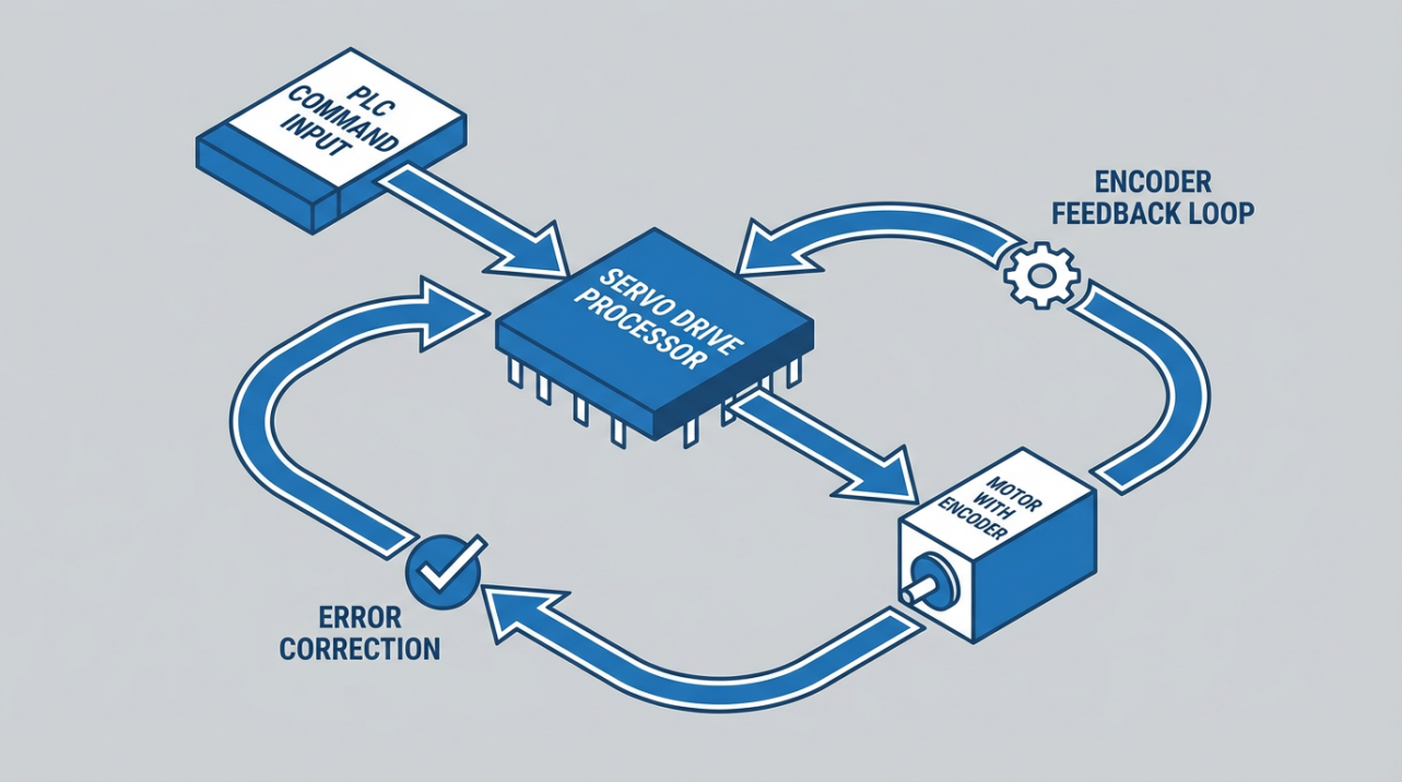
A servo drive is a closed‑loop motor controller. It amplifies commands from a PLC or motion controller and regulates power to a servo motor so that position, speed, and torque follow the setpoints precisely. The drive reads feedback from an encoder or resolver, computes error between commanded and actual motion, and constantly adjusts current to the motor to minimize that error.
For high‑power industrial applications, the drive’s power stage is typically fed from a 3‑phase, 400 V‑class AC supply, rectified internally to a DC bus. This is the domain of multi‑kilowatt machines, heavy axes, high‑throughput packaging lines, and induction‑motor servo systems. THM Huade, for example, describes 380 V three‑phase servo drive families spanning roughly 5.5 kW up to 75 kW, which is the scale where 400 V three‑phase becomes the practical choice.
The key distinction from a simple variable frequency drive is feedback and control intent. A VFD mostly controls speed, often open‑loop, as you see on fans and pumps. A servo drive closes the loop on torque, speed, and position with high‑resolution feedback. Articles from THM Huade, ADVANCED Motion Controls, and others converge on the same point: servos are for precise, dynamic motion where you care about millisecond‑level response and repeatable position, not just turning a shaft.
Why 400 V Three‑Phase for High Power
In lower‑power applications you can get away with 24 V or 48 V DC servo drives. Once you move into multi‑kilowatt territory, a 400 V three‑phase supply becomes attractive for several reasons.
First, higher bus voltage means you can deliver the same power at lower current. That reduces I²R losses in cabling and bus bars and keeps conductor sizes manageable. Celera Motion’s analysis of servo drive efficiency emphasizes how conduction losses grow with the square of current; every amp you eliminate at a given power point is worth fighting for.
Second, 400 V three‑phase supplies are standard in industrial facilities for heavy loads. Control Engineering’s energy‑efficiency work with Yaskawa servopacks specifically references 400 V servo amplifiers as the core of high‑performance, energy‑efficient machine architectures. When you design around the same voltage level as the rest of the plant, you simplify distribution, protection, and spares.
Third, a 400 V servo system can share technology with asynchronous‑motor servo drives. Research on energy‑saving control strategies for 400 V induction‑motor servo drives shows that high‑power positioning tasks can be handled efficiently with vector control and optimized motion profiles, even with standard induction machines. That gives you more options in applications where you want servo‑like performance from rugged, readily available motors.
The tradeoff is that fault energy is much higher at 400 V than at extra‑low voltage. This puts more pressure on your insulation system, protection, grounding, and mechanical integration. It is one reason I always tell project teams that a 400 V servo drive is not a “bigger 48 V drive”; it is a different class of equipment that demands more discipline.
Core Architecture: From 400 V Bus to Precise Motion
Every modern 400 V servo drive aimed at industrial motion control is built around the same basic blocks described in Celera Motion’s engineering paper on servo‑drive efficiency.
The power stage is the dominant element. It is usually a three‑phase bridge composed of six MOSFET or GaN transistors. The drive rectifies the three‑phase AC input to a DC bus, then uses pulse‑width modulation at frequencies typically in the 20 kHz to 200 kHz range to synthesize AC phase voltages for the motor. Because the motor windings are inductive, this high‑frequency PWM averages into smooth current.
Conduction losses arise whenever current flows through a transistor that behaves like a small resistor. The loss is proportional to the device’s on‑resistance and to the square of the phase current. These losses grow with temperature because the on‑resistance increases as the silicon heats. This is why thermal design and derating matter so much more at 400 V and high current than at low power.
Switching losses occur during each transition from off to on and back again. In an ideal world the transistor would never have high voltage and high current at the same time. In reality, there is a finite transition time—on the order of tens of nanoseconds—when both are significant, and instantaneous power spikes.
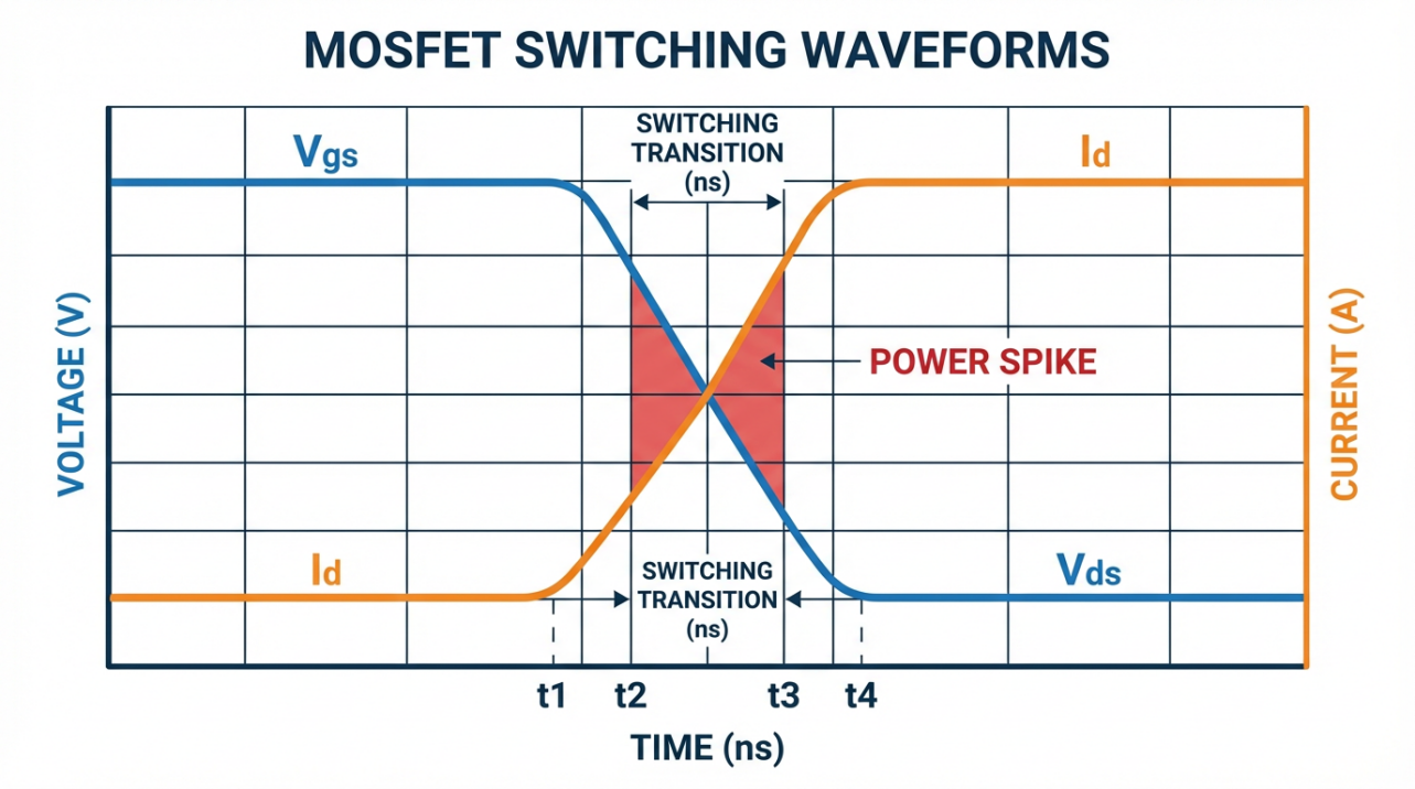
Celera Motion notes that average switching loss is proportional to bus voltage, phase current, and switching frequency. Once you accept that, you stop blindly turning switching frequency up “for better current ripple” and start balancing it against loss and heat.
In addition to the main bridge, every digital servo drive contains internal DC/DC converters that reduce a logic supply (often around 24 V) down to internal rails such as 5 V, 3.3 V, or lower. Even with state‑of‑the‑art designs, these converters typically reach only around 90 to 95 percent efficiency, meaning up to about 10 percent of logic power becomes heat. At low power it is a nuisance; at high power with many axes, logic losses become a noticeable part of the thermal budget.
Logic processors and communication transceivers consume power too. Their absolute wattage is modest compared with the power stage at full load, but in standby or light‑load operation they dominate losses. Celera Motion defines standby conditions as having communication active, motion controllers running at full loop rate, DC bus present, the power stage enabled and switching, but zero output current. In intermittent‑motion high‑power machines, that standby behavior can be the difference between an efficient system and one that quietly wastes energy all day.
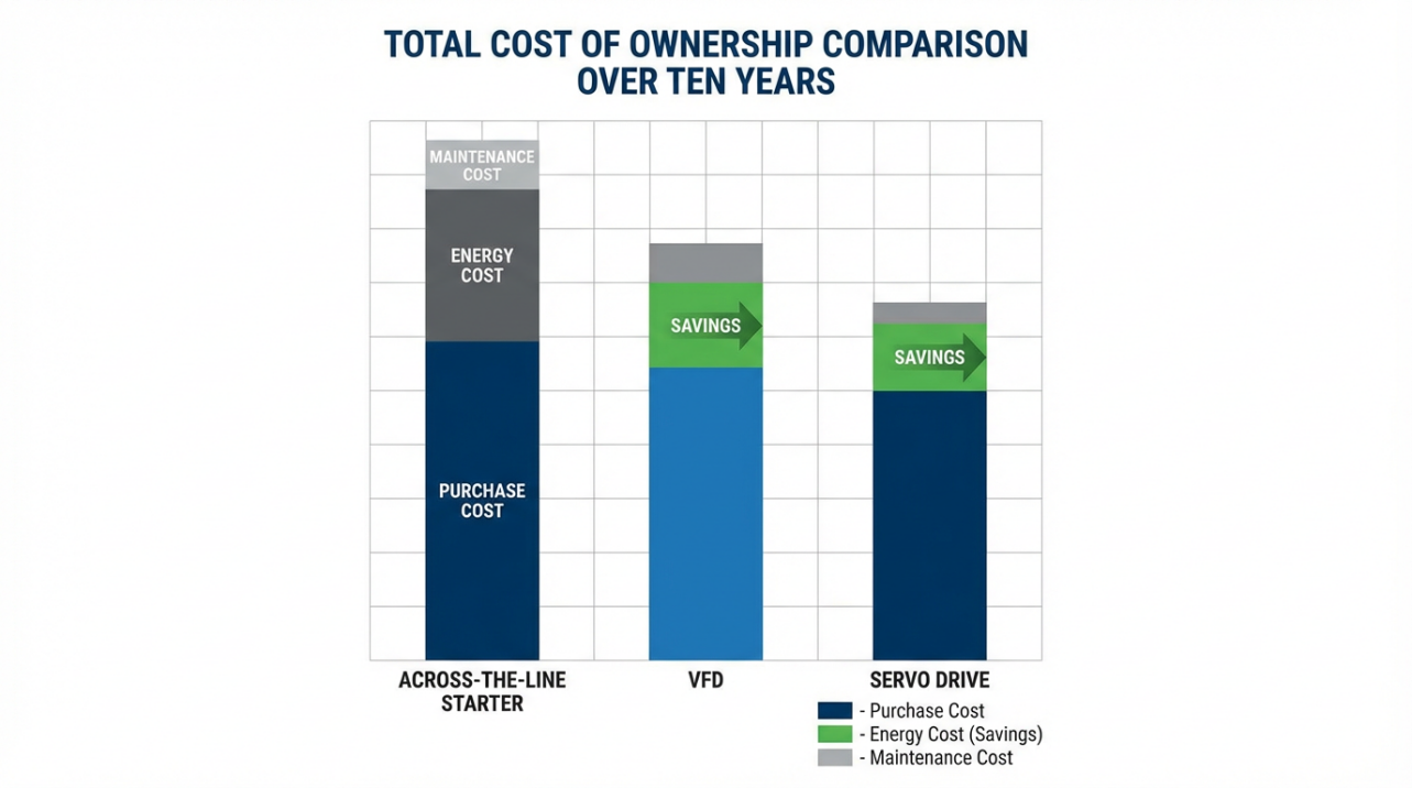
Servo Drive vs VFD vs Across‑the‑Line at High Power
For 400 V three‑phase machinery, you usually have three architectural options: across‑the‑line starters, VFDs, or servo drives. Control Engineering’s discussion of energy efficiency across these options, together with Yaskawa’s servopack examples and U.S. Department of Energy guidance, paints a fairly clear picture. The table below summarizes the comparison in the context of high‑power motion.
| Aspect | Across‑the‑Line Starter | VFD (Speed Drive) | 400 V Servo Drive |
|---|---|---|---|
| Control objective | Run/stop at fixed speed | Speed control, often open‑loop | Closed‑loop torque, speed, and position |
| Energy use at low demand | Draws full current whenever energized | Reduced energy at partial speed | On‑demand torque; current can drop to near zero at idle |
| Typical efficiency gains | Limited | Significant in variable‑torque loads | Can cut machine energy roughly in half in some retrofits |
| Impact on motor life | High starting stress | Reduced electrical and mechanical stress | Optimized trajectories and lower heat for longer life |
| Suitability for precision | Poor | Moderate | Excellent, sub‑millimeter and sub‑degree positioning |
Control Engineering presents a case where replacing across‑the‑line starters with servo systems allowed machines to deliver torque only when needed and to drop to almost zero torque at idle. That change alone can cut energy usage roughly in half compared with pumps or hydraulic sources that must run continuously in case of demand.
In my own projects, whenever a high‑power axis needs precise profiles, synchronized motion, or frequent starts and stops, the servo drive inevitably wins on total cost of ownership, even if the purchase price is higher than a basic VFD or starter.
Matching a 400 V Servo Drive to Motor and Load
Choosing the right 400 V three‑phase servo drive starts with the mechanics, not with a catalog.
Festo, Heidenhain, and several motor manufacturers all stress the same sizing path. You first define the motion profile and load. That means payload weight, distances and angles, desired cycle times, and rest or dwell intervals. From this, you calculate required torque across the duty cycle, both continuous (RMS) and peak, and you compute the load inertia reflected to the motor shaft.
The motor’s torque constant relates torque to phase current; dividing required torque by that constant gives you an estimate of phase current. Celera Motion notes that this relationship is approximate and that factors such as losses and temperature influence the actual ratio, but it is good enough for drive sizing. For Y‑connected brushless motors, the drive’s phase current is essentially the motor’s phase current. For delta‑connected motors the drive phase current is higher by a factor of the square root of three, which has to be accounted for when you are trying to keep conduction losses under control.
On the motor side, Heidenhain explains that you must place the continuous operating point within the continuous region of the torque‑speed curve and keep peak demands in the intermittent region. Many servo motors have a peak‑to‑continuous torque ratio on the order of four to one. Kollmorgen points out that most modern servo drives advertise only two to three times peak‑to‑continuous current capability, and that peak is available only for brief periods—on the order of seconds. At 400 V and multi‑kilowatt power levels, ignoring that detail is a recipe for nuisance tripping or overheating.
Once the motor is selected, you then choose a drive whose voltage and current ratings are compatible. Application notes from various manufacturers emphasize that the drive’s continuous current must safely exceed the motor’s continuous current, and its peak current must cover the motor’s peak requirement. If the drive’s continuous rating exceeds the motor’s, temperature monitoring and conservative tuning are strongly recommended to avoid overheating the motor.
One more step is often overlooked: inertia matching. Festo and others highlight the importance of the ratio between load inertia and motor inertia. A very large mismatch leads to sluggish response and oscillation; a very low ratio can waste motor capability. Gearboxes and reducers are your friend here, particularly at 400 V where you are typically using high‑speed windings and can trade speed for torque and better inertia ratios.
A concise way to think about it is this: at high power you are not simply choosing “a 400 V, 10 A drive.” You are matching the electrical capability of that drive to the mechanical reality of your axis across its entire duty cycle.
Communication, Control Modes, and Feedback at Scale
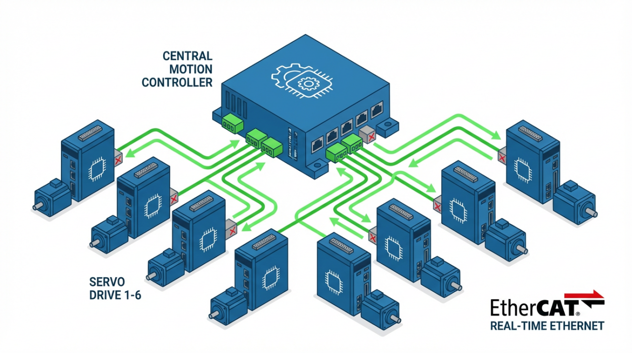
On large machines, how you integrate 400 V servo drives into the control architecture matters almost as much as their individual ratings.
ADVANCED Motion Controls and other drive vendors describe three primary operating modes: torque (or current) mode, velocity mode, and position mode. In torque mode, the drive regulates current and leaves velocity and position loops to a higher‑level controller. In velocity mode, the drive closes the speed loop; in position mode it handles the entire cascade. In multi‑axis high‑power machines, I usually prefer torque mode on distributed drives when a sophisticated central controller is available, because it allows tightly coordinated trajectories while keeping intelligence at the top level. For simpler single‑axis systems, position mode inside the drive can simplify the controller and wiring.
Network choice is another area where early decisions pay off. Both the CNCouke and ADVANCED Motion Controls briefs stress that digital servo drives support networked control with fieldbuses such as EtherCAT, PROFINET, EtherNet/IP, CANopen, and Modbus. Real‑time Ethernet variants allow tight synchronization across multiple axes, which is indispensable for printing, web handling, and high‑precision packaging. Slower buses can be perfectly adequate where motion is less dynamic.
Feedback compatibility is non‑negotiable. Servo drives must accept the specific encoders or resolvers on your motors, whether they are incremental or absolute, and must support the resolution and protocol required. High‑resolution feedback devices are particularly important in compact, high‑precision machines and high‑power servo presses where any backlash or quantization error is amplified by the large forces involved.
Finally, remember that every active communication port and processing core consumes power. Celera Motion explicitly calls out communication transceivers as contributors to standby losses, especially Ethernet ports that draw power just by being connected. On multi‑axis, high‑power installations, I routinely disable unused ports and services to save both energy and thermal headroom.
Efficiency and Power Loss at 400 V: Where the Watts Go
Energy efficiency is not only a sustainability talking point; it is a machine‑design variable with tangible implications for panel cooling, uptime, and operating cost.
Celera Motion’s work on servo‑drive efficiency breaks losses into three main categories: power‑stage losses, internal DC/DC losses, and logic and communication losses. Power‑stage losses dominate at high load. DC/DC and logic losses dominate when everything is powered up but motion is intermittent.
On the motor and mechanics side, the U.S. Department of Energy’s motor‑systems guidance points to copper losses in the windings, iron losses in the magnetic core, and mechanical losses in bearings and gears. Academic work on energy‑saving control strategies for induction‑motor servo drives brings these ideas together into a single energy framework. In that work, the authors define total energy as the sum of copper losses and mechanical work over the maneuver time and derive an optimal acceleration profile that minimizes energy for a given move time.
For constant‑torque loads, they show analytically that the optimal acceleration and deceleration phases should each consume one third of the total maneuver time. For more complex loads—where torque depends on speed with viscous and aerodynamic components—they derive cubic and higher‑order equations and solve them numerically. In practical test cases with a 1.5 kW, 400 V induction motor, the energy‑optimal trapezoidal speed profile reduced input energy by roughly 3.8 to 4.4 percent compared with a simple triangular profile, with very good agreement between simulation and experiment.

For more strongly speed‑dependent loads, simulations showed potential savings up to about 23 percent in specific scenarios.
Control Engineering’s case study on replacing across‑the‑line starters with servomotors and servopacks makes the same point from a practical angle. Across‑the‑line starters energize the motor windings directly from the line and keep them energized as long as the panel is on, drawing steady current regardless of actual load. In contrast, servo systems provide on‑demand torque and can drop to near‑zero torque and much lower current when the machine is idle. In some installations that alone has been enough to cut total machine energy use roughly in half.
When you combine these insights with the U.S. Department of Energy’s observation that motor‑driven systems often consume 60 to 70 percent of a plant’s electricity, it becomes obvious that optimizing 400 V servo drives is not a fringe exercise. It is central to plant‑wide energy and thermal management.
Practical Strategies to Improve 400 V Servo Drive Efficiency
From an integrator’s standpoint, you have three levers: hardware selection, parameterization and control strategy, and day‑to‑day operating practice.
On the hardware side, Celera Motion recommends using dual supplies where possible, with a separate lower‑voltage logic supply. That allows the DC/DC converters to work from a lower input and operate more efficiently. They also recommend using the minimum logic supply voltage that still satisfies any other functions, such as electro‑mechanical brakes.
For the power stage, both Celera Motion and the induction‑motor optimization work recommend using the minimum bus voltage and switching frequency compatible with your speed, acceleration, and current‑loop bandwidth requirements. Because switching losses scale with both bus voltage and frequency, that choice can significantly reduce heat. At 400 V levels this is especially important because the thermal penalty of every wasted watt is magnified in enclosure design and cooling capacity.
On the control‑strategy side, parameter optimization is critical. THM Huade describes a practical workflow: analyze motion profiles, use the drive’s auto‑tuning to capture motor dynamics, then manually refine gain and limit parameters for your specific load and performance targets. Correct tuning reduces vibration, overshoot, and lag, which in turn reduces mechanical stress and current spikes. It also enables more aggressive yet energy‑optimal profiles such as the trapezoidal trajectories mentioned earlier.
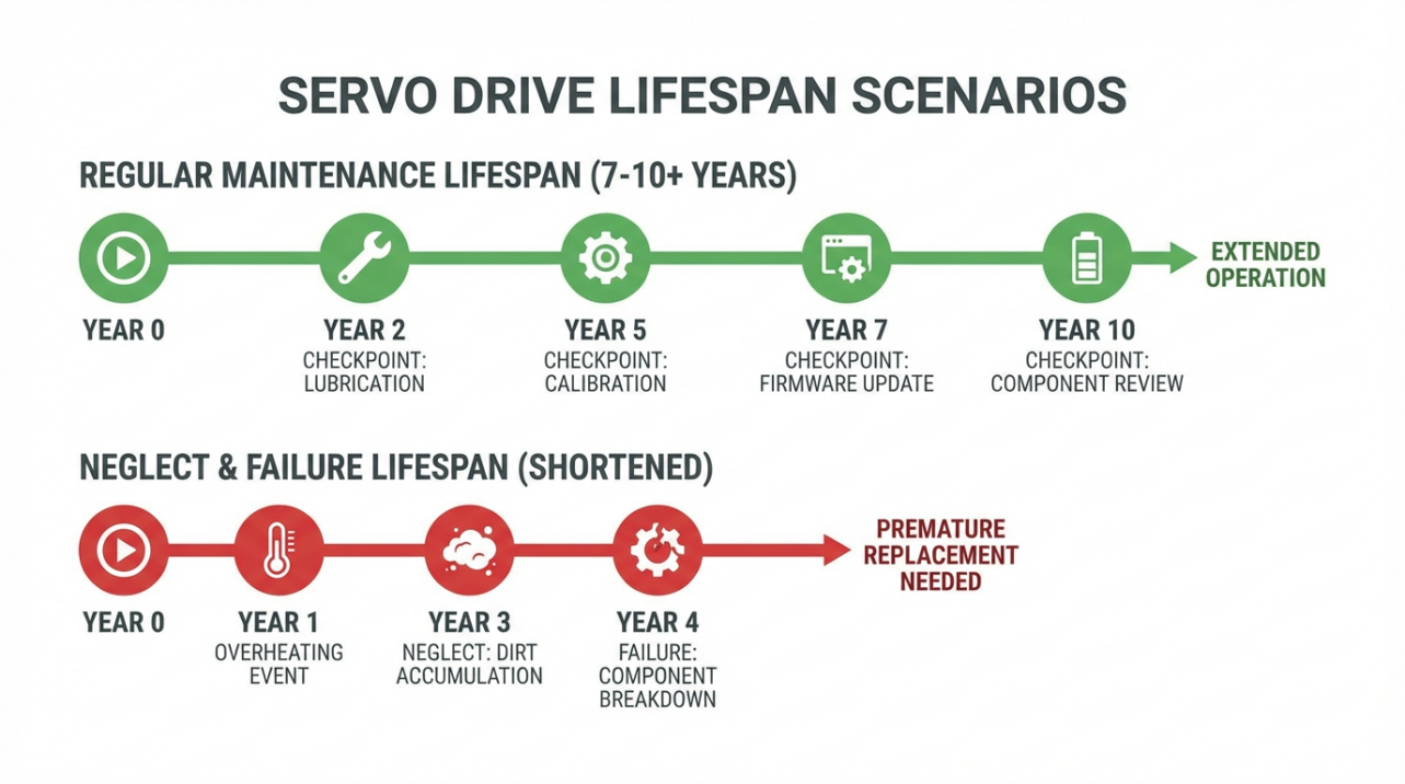
Finally, operational practice matters. Routine checks for unusual noise, vibration, and overheating, regular cleaning and lubrication of mechanical components, and keeping firmware up to date all contribute to maintaining efficiency over the life of the system. CNCouke notes that industrial servo drives commonly have lifespans on the order of seven to ten years when properly maintained and operated within specification; poor maintenance and thermal abuse shorten that significantly.
Environmental, Thermal, and Mechanical Integration
A 400 V three‑phase servo drive rarely lives in a friendly environment. CNCouke and several motor manufacturers highlight ambient temperature, humidity, altitude, and electrical noise as selection and design constraints. High ambient temperatures reduce continuous torque capability and may demand larger heatsinks, forced air, or even liquid cooling. Dirty or wet environments call for enclosures with appropriate ingress protection and careful segregation between power and signal wiring.
From a thermal standpoint, Celera Motion presents a simple dissipation model that links drive power losses to the required thermal resistance of the heatsink path. In practice, for a high‑power 400 V axis, you must consider the entire heat‑removal chain: transistor junctions to the drive case, case to panel, panel to air, and the enclosure’s ability to shed heat to the surrounding space. If I see a full‑load thermal model that assumes an ambient temperature close to office conditions in a facility that runs hot, I know we are headed for trouble.
Mechanical installation matters as well. CNCouke and THM Huade both call out panel space, mounting orientation, cabling, and accessibility as factors. Poor cable routing that bundles high‑current motor leads with feedback wiring is an invitation to noise problems, especially at the fast edge rates of modern drives. It is increasingly common to use high‑quality, application‑rated cables with separate routing for power and signal, and to maintain physical distance from known electromagnetic interference sources such as transformers and large contactors.
Common Pitfalls I Still See with 400 V Servo Drives
Even in modern plants, the same classes of mistakes show up again and again.
One recurring issue is treating peak current as a continuous capability. Engineers size a drive so that its peak current equals the motor’s peak requirement, then run motion profiles that demand near‑peak current for long stretches. This overheats the drive, the motor, or both. Remember that most servo drives only allow peak current for short bursts and that motors are rated with a clear distinction between continuous and intermittent torque.
Another common pitfall is ignoring standby and partial‑load behavior. A program may leave all axes energized and under servo control even when a machine is idle for long periods. The result is that logic processors, communication transceivers, and switching losses in the power stage all continue generating heat and consuming power. Thoughtful use of enable signals, energy‑saving modes, and safe torque off can reclaim that wasted energy without compromising safety.
A third problem is underestimating the effect of mechanical design on the drive. Oversized or poorly balanced loads, excessive backlash, and compliance not only degrade positioning accuracy but can force aggressive tuning that drives currents up and pushes power devices into hotter operating zones. As Festo and Heidenhain emphasize, getting inertia and mechanical stiffness right is just as important as electrical sizing.
Finally, there is a tendency to treat energy studies as once‑off justification exercises rather than as ongoing diagnostics tools. Control Engineering’s examples using power analyzers over multi‑day periods show how valuable continuous measurements of power, energy, and power factor can be. Running comparative studies before and after machine modifications, while holding the workload constant, is one of the most reliable ways to verify that your 400 V servo system is delivering the efficiency improvements you expect.
Short FAQ
Are 400 V three‑phase servo drives always more efficient than lower‑voltage alternatives?
Not automatically. Higher voltage reduces current for a given power level, which tends to reduce conduction losses in cables and devices. However, Celera Motion’s analysis shows that switching losses scale with bus voltage. In practice, 400 V three‑phase drives make sense for high‑power applications where the mechanical work justifies that voltage level. For small axes, extra‑low‑voltage drives can be simpler and very efficient. The right choice depends on power level, distance to the motor, and overall architecture.
When should I choose a 400 V servo drive instead of a VFD?
Choose a 400 V servo drive when you need precise, repeatable control of position, speed, and torque, particularly with dynamic motion profiles and frequent reversals. Control Engineering’s comparison of across‑the‑line starters, VFDs, and servo systems shows that servos excel in on‑demand torque applications and can significantly reduce energy use in machines that do not run at constant speed. For simple variable‑speed pumps or fans with no precision requirements, a VFD is usually sufficient and more economical.
What lifespan can I expect from a 400 V servo drive?
CNCouke reports typical industrial servo drive lifespans in the seven to ten year range when units are correctly installed, operated within their ratings, and maintained. Heavy thermal cycling, dirty or hot environments, and repeated operation at or beyond peak limits shorten that life. Good panel design, periodic maintenance, and conservative tuning extend it.
Closing on a pragmatic note, a 400 V three‑phase servo drive is one of the most capable tools you can put into a high‑power motion system, but it will only be as good as the engineering discipline around it. When you match drive, motor, and mechanics carefully, respect the physics of losses and heat, and validate performance with real energy measurements rather than assumptions, you end up with machines that run cooler, last longer, and deliver the throughput your production team expects. That is the kind of project outcome a seasoned integrator is willing to put their name on.
References
- https://www.academia.edu/114815951/Energy_saving_control_strategy_of_servo_drives_with_asynchronous_motor
- https://www.energy.gov/sites/prod/files/2014/04/f15/amo_motors_handbook_web.pdf
- https://www.cs.rochester.edu/u/nelson/courses/csc_robocon/robot_manual/motor_drivers.html
- https://www.a-m-c.com/how-to-select-a-servo-drive/
- https://www.cncouke.com/blog/how-to-select-the-best-servo-drive-for-industrial-applications
- https://www.controleng.com/motors-and-drives-three-topics-in-energy-efficiency/
- https://thmhuade.com/a-buyers-guide-to-industrial-servo-drives-features-specs-and-cost-considerations/
- https://www.thservodrive.com/blog/how-to-optimize-the-performance-of-a-servo-drive-system-1542070.html
- https://www.x-teamrc.com/how-to-choose-the-right-driver-for-a-servo-motor/
- https://www.elmomc.com/blog/how-to-choose-servo-drive-1-2/
Keep your system in play!
Top Media Coverage
Categories


Related articles Browse All
-
 amikong NewsSchneider Electric HMIGTO5310: A Powerful Touchscreen Panel for Industrial Automation2025-08-11 16:24:25Overview of the Schneider Electric HMIGTO5310 The Schneider Electric HMIGTO5310 is a high-performance Magelis GTO touchscreen panel designed for industrial automation and infrastructure applications. With a 10.4" TFT LCD display and 640 x 480 VGA resolution, this HMI delivers crisp, clear visu...
 -
 BlogImplementing Vision Systems for Industrial Robots: Enhancing Precision and Automation2025-08-12 11:26:54Industrial robots gain powerful new abilities through vision systems. These systems give robots the sense of sight, so they can understand and react to what is around them. So, robots can perform complex tasks with greater accuracy and flexibility. Automation in manufacturing reaches a new level of ...
 -
 BlogOptimizing PM Schedules Data-Driven Approaches to Preventative Maintenance2025-08-21 18:08:33Moving away from fixed maintenance schedules is a significant operational shift. Companies now use data to guide their maintenance efforts. This change leads to greater efficiency and equipment reliability. The goal is to perform the right task at the right time, based on real information, not just ...


- Q&A
- Policies How to order Part status information Shipping Method Return Policy Warranty Policy Payment Terms
- Asset Recovery
- We Buy Your Equipment. Industry Cases Amikong News Technical Resources Why choose us
- ADDRESS
-
 32D UNITS,GUOMAO BUILDING,NO 388 HUBIN SOUTH ROAD,SIMING DISTRICT,XIAMEN
Leave Your Comment