
-
Please try to be as accurate as possible with your search.
-
We can quote you on 1000s of specialist parts, even if they are not listed on our website.
-
We can't find any results for “”.
VFDs with Built‑in Brake Choppers: The Workhorse of Regenerative Braking Systems
Why Regenerative Braking Belongs in Your Plant
If you spend any time around industrial power distribution, you know electric motors quietly eat most of the electricity bill. Industry sources describe machine‑driven processes as a dominant consumer in manufacturing, with motors powering elevators, cranes, hoists, conveyors, fans, pumps, and every kind of motion system you can imagine. The way you control those motors is one of the biggest levers you have on both energy cost and reliability.
Variable frequency drives, or VFDs, are already standard practice for speed control and soft starting. The next frontier is what happens when drives need to slow down or lower a load. In traditional systems, the answer is simple but wasteful: convert that braking energy to heat in resistors or mechanical brakes and throw it away. Modern regenerative drive technology, described by manufacturers such as ABB, Siemens, and others, flips that script by capturing braking energy and feeding it back to the DC bus or even to the grid.
Some engineers hear “regenerative braking” and think only of sophisticated active front ends or complex multi‑axis DC bus systems. In the field, the real story is more nuanced. For many cranes, elevators, hoists, and conveyors, a VFD with a built‑in brake chopper and a well‑sized resistor is the practical backbone of a regenerative braking system. It does not always send energy back to the utility, but it gives you controlled braking, protects the drive from overvoltage trips, and provides a solid base if you decide to add true line‑regenerative hardware later.
After a few decades commissioning drives on hoists, elevators, and high‑inertia machines, I tend to start my conversations there: understand the energy path, use the brake chopper correctly, and then decide whether you really need to go all the way to a fully regenerative front end.
How a VFD Handles Energy in Motoring and Braking
To understand where the brake chopper fits, you need a clear picture of how a standard VFD manages power. Technical explanations from ETech Group, LSElectric America, and others all follow the same architecture.
A typical VFD has three main power stages. The rectifier stage takes the fixed‑frequency AC line and converts it to DC. In most standard drives, this is a simple diode or thyristor bridge and power can flow only one way, from the grid into the drive. The DC bus is next. Capacitors and sometimes inductors smooth the rectified DC and act as an energy buffer. Finally, the inverter stage uses IGBTs with pulse‑width modulation to synthesize a new AC waveform at whatever frequency and voltage the control circuit commands.
In motoring mode, energy flows from the grid, through the rectifier, into the DC bus, out through the inverter, and into the motor. The motor converts that electrical energy to torque on the shaft to lift a hoist, move a conveyor, or turn a centrifuge. When the load is driving the motor instead, the physics simply reverse. As several sources, including eMotors Direct and Darwin Motion, point out, motors are bidirectional energy conversion devices. If the rotor is driven faster than the synchronous speed set by the stator field, the machine behaves as a generator and sends power back toward the drive.
During deceleration or when lowering a load, that is exactly what happens. The motor pushes current back into the inverter, which pushes it into the DC bus. Since the standard rectifier is one‑way, the bus voltage starts to rise. If you do nothing, it will rise until the drive protects itself with a DC bus overvoltage trip, and the load is left to coast uncontrolled. That is not acceptable when you are talking about a crane, elevator, or downhill conveyor.
You now have three basic options.
You can stretch out the deceleration so the small losses in the motor and drive absorb the energy over a longer time. Invertek notes that this is sometimes viable for low‑inertia fans but quickly produces unreasonably long stopping times for heavier loads. You can let the motor coast by simply opening the IGBTs and allowing the load to spin down on its own, which is only acceptable where uncontrolled stopping is harmless. Or you can provide a deliberate place for the regenerative energy to go. That is where brake choppers, dynamic braking resistors, and line‑regenerative units come into play.
What a Brake Chopper Actually Does
The eMotors Direct and Invertek technical notes describe the brake chopper in straightforward terms. It is basically a high‑speed electronic switch, almost always an IGBT, connected across the DC bus with a braking resistor in series. The VFD monitors the DC bus voltage. When regeneration pushes the bus above a set threshold, the brake chopper turns on and diverts current into the resistor. The resistor converts the electrical energy into heat. When the bus voltage falls back below the threshold, the chopper turns off.
Functionally, that gives you controlled, repeatable dynamic braking without overvoltage trips. Invertek explains that with a correctly specified braking resistor, the drive can allow approximately full load current to flow regeneratively into the DC link, with the resistor converting that power into heat to support fast, controlled stopping or lowering.
In many modern drives, the braking IGBT is built in, even on relatively small frame sizes. Invertek notes that its E3 and P2 families, including an elevator variant, include internal braking transistors so you only need to add an external resistor. That is exactly what people mean when they talk about a VFD with a built‑in brake chopper. The chopper circuitry is native to the drive; you simply run two wires to an appropriately sized resistor bank.
In field terms, this has three important implications. First, the drive can handle regenerative energy as part of normal operation, not as an afterthought. Second, panel design is simpler because the switching element and protective logic are already engineered and tested as part of the drive. Third, you can choose whether to keep things simple with dynamic braking only, tie several drives together on a common DC bus to share energy, or add a line‑regenerative module later to push energy back to the grid.
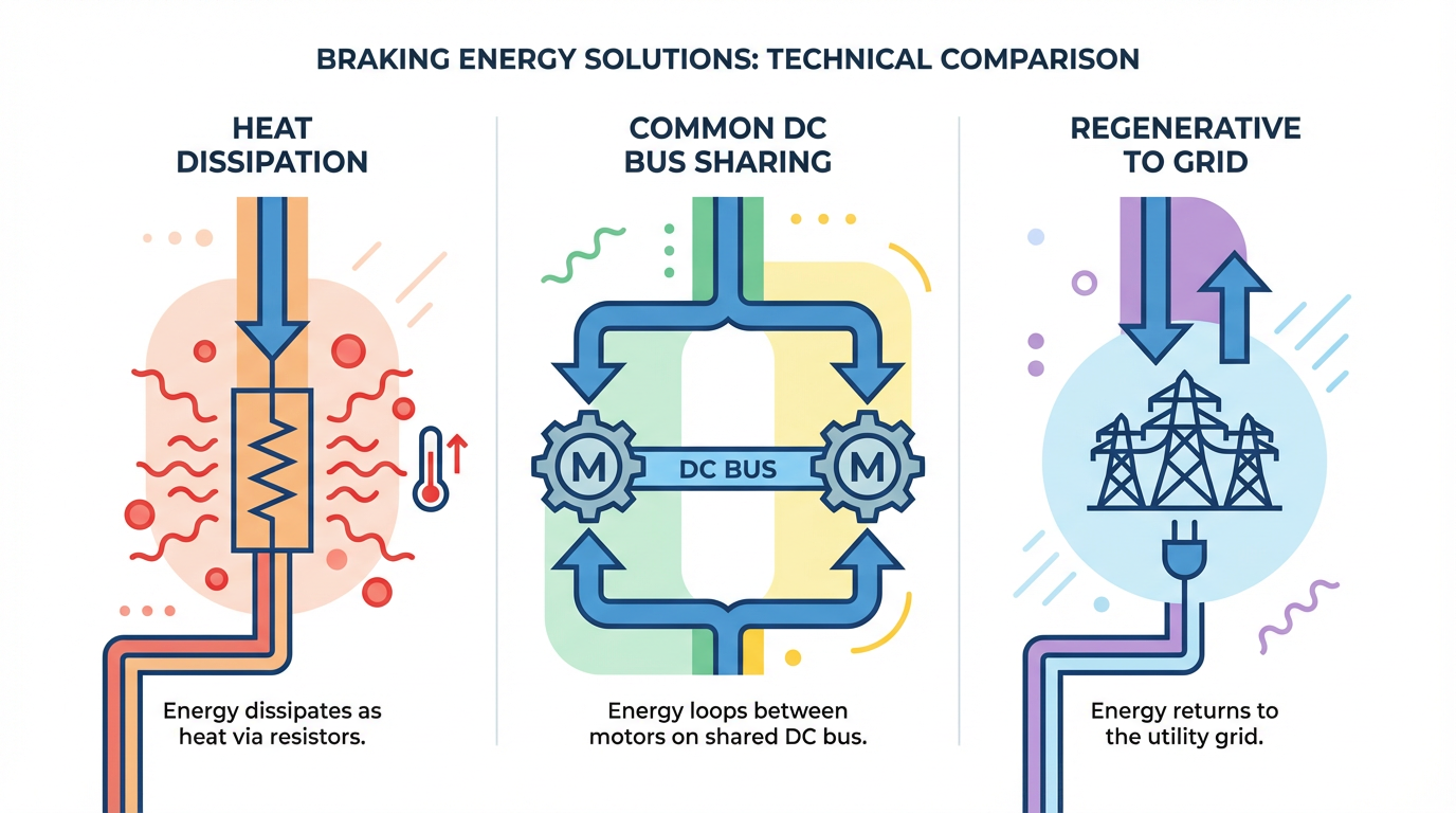
Regenerative Braking Options: Dissipate, Share, or Return
Different references describe the same basic menu of options whenever a motor goes into generating mode and pushes energy back into the drive. It helps to think in terms of where the energy ultimately ends up.
| Braking method | Where the energy goes | Typical duty pattern | Main advantages | Main limitations and risks |
|---|---|---|---|---|
| Dynamic braking with resistor | Heat in external resistor | Occasional to frequent braking | Simple, low capital cost, works with standard drives | Wasted energy, extra heat in or near the cabinet |
| Coasting or extended decel ramps | Internal losses in motor and drive | Light inertia, noncritical stopping | No extra hardware, minimal complexity | Long stopping times, no controlled braking when coasting |
| Common DC bus sharing | Other drives on same DC bus | Multi‑axis systems, mixed motoring/regen | Reuses energy internally, fewer or smaller resistors | No energy back to grid, more complex DC bus design |
| Line‑regenerative front end or unit | Back to plant power network | Frequent or continuous high‑duty regen | Energy savings, less panel heat, improved power quality | Higher capital cost, utility interconnection considerations |
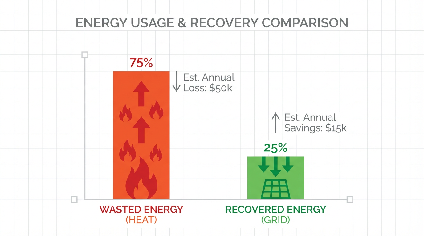
This table is not theoretical. Industrial Automation Co. walks through a very practical calculation on a 30 kW motor that regenerates about 10 kW for 3 seconds, 200 times per hour. By their estimate, that works out to around 6,900 kWh per year of energy you either burn up in a resistor or feed back to the line. A Control Engineering article takes a 45 kW elevator and shows that conventional braking can waste around 11,300 kWh per year as heat, while a regenerative unit in that case can recover about 54 percent of that energy, saving roughly $1,000 per year at typical electricity rates.
On the other end of the spectrum, Darwin Motion and other suppliers of regenerative VFDs quote energy consumption reductions on the order of up to about 30 percent in suitable applications. More general VFD efficiency studies, such as those referenced by LSElectric America, describe efficiency improvements in the range of roughly 20 to 30 percent when VFDs are properly applied to motor systems.
The point is not that every hoist or elevator will exactly match these figures. The takeaway is that real industrial case studies consistently show meaningful, recurring savings once you stop throwing braking energy away as heat.
Where a Brake‑Chopper VFD Is the Right Tool
With those options on the table, it is fair to ask why veteran integrators still specify VFDs with built‑in brake choppers so often, instead of jumping straight to active front ends or standalone regenerative modules.
The real answer is that duty cycles and practical constraints vary. Invertek emphasizes that dynamic braking using a chopper and resistor is well suited to low and medium power drives and to applications with occasional or moderate braking. Tusk Automation echoes the same point from a hoist perspective: any application that frequently lowers or decelerates loads must provide a controlled way to handle the excess regenerative power, or you invite overvoltage faults and potential damage.
In day‑to‑day project work, VFDs with brake choppers hit a sweet spot in several scenarios. They are ideal when you need aggressive stopping or tightly controlled lowering but the braking duty is intermittent enough that the energy savings from line regeneration would not justify the additional capital cost and complexity. Examples include many bridge and trolley motions on cranes, smaller hoists, and material handling conveyors that stop and start on a moderate cycle. They are also compelling when panel heat is manageable and cabinet real estate is limited. Dynamic braking resistors must be mounted where their heat can dissipate, often outside the cubicle as Invertek recommends, but they do not require the extra footprint and wiring that line‑regenerative modules often do.
VFDs with built‑in brake choppers also make sense when you want to keep the electrical architecture simple. There is no need to coordinate harmonic compliance or utility interconnection rules for high‑duty regeneration. As Industrial Automation Co. notes, regenerative converters and active front ends introduce their own design considerations related to harmonics and power quality. With a chopper‑based approach, you are effectively isolating the braking energy problem within your drive panel and the resistor bank.
Finally, brake‑chopper VFDs fit nicely into stepwise modernization programs. Plants running older across‑the‑line or soft‑starter controls can move first to VFDs with braking capability to gain better acceleration, deceleration, and speed control. That alone often reduces downtime and mechanical wear. Later, if energy costs or sustainability targets justify it, you can add a line‑regenerative unit or convert selected axes to active front ends, knowing that your drives already handle their own braking behavior safely if the regen path is unavailable.
Design Details You Cannot Afford to Ignore
When you build a braking strategy around a VFD with a built‑in brake chopper, the quality of your engineering shows up in resistor sizing, thermal design, and drive parameterization.
Invertek lays out practical selection guidelines for the resistor bank. The resistor needs a DC voltage rating suitable for the bus voltage. It must respect the minimum resistance value specified by the drive so that the braking IGBT is not asked to conduct more current than it can safely handle. Its power rating needs to match the expected braking energy over the duty cycle; undersizing here is a common field mistake that leads to overheated resistors, nuisance trips, or worse. Mechanically, the resistor should be mounted where it is protected from liquids, dust, and accidental human contact, which often means outside the main enclosure with appropriate guarding.
Industrial Automation Co. warns about the temptation to throw ever larger braking resistors at aggressive deceleration profiles without respecting panel thermal limits. Each kilowatt you dissipate in that resistor ends up as heat that your cabinet and surrounding space have to absorb. In tight mechanical rooms or already warm environments, that can create serious reliability issues for the rest of your control gear.
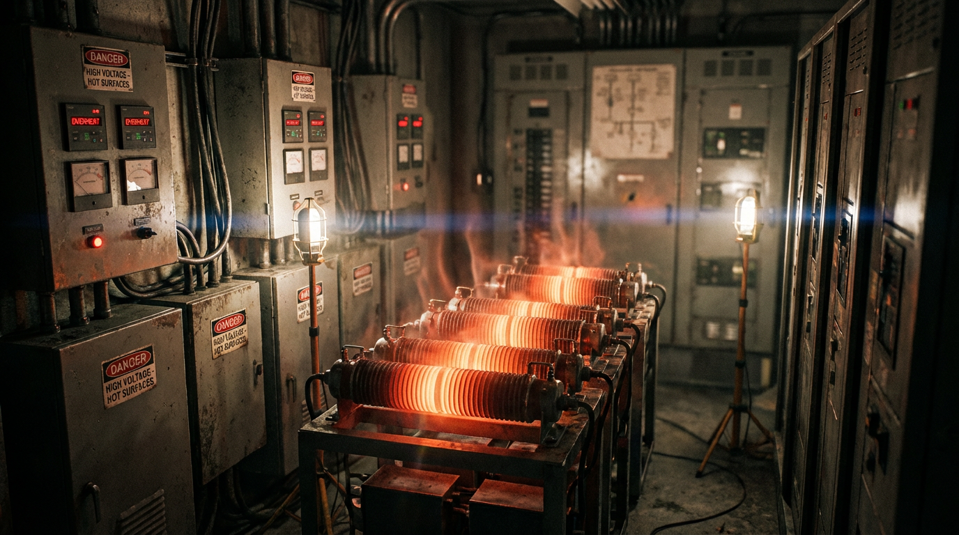
In those cases, regenerating back to the line becomes attractive not only for the energy savings but also for the reduction in panel heat and cooling requirements.
Drive parameterization matters just as much. The same Industrial Automation Co. guidance emphasizes that deceleration ramps and braking thresholds must be tuned thoughtfully to avoid constant cycling of the chopper or nuisance DC bus overvoltage trips. ETech Group and other motor control experts point out that drives generally allow overload capabilities on the order of about 150 percent of rated current for a minute and higher short‑term peaks. If your deceleration demands exceed what the motor and drive combination can safely deliver, no amount of clever braking hardware will solve the problem; you may need to change the mechanics or accept longer decel times.
In multi‑drive systems, KEB describes common DC bus architectures where several inverters share a DC link. In that configuration, regeneration from one axis can be used immediately by another that is motoring before any surplus energy is sent to a resistor or back to the grid. They recommend additional DC fusing and careful design of the rectifier or active front end feeding that bus. In a setup like this, brake‑chopper VFDs still make sense on individual axes as a local safety net. If the common bus or line‑regenerative unit is unavailable, the built‑in chopper can protect the drive by falling back to dynamic braking.
Avoiding Marketing Traps: “Regeneration” vs. Heating the Motor
One of the more useful technical notes in the research set comes from vfds.org, which cautions against marketing language that blurs the lines between true regenerative braking, dynamic braking, and flux‑based braking methods.
The author makes a simple but important point: regeneration itself is not a problem to be fought. It is just the condition of energy flowing from the load and motor back toward the drive. The real design question is where that energy ends up. Dynamic braking sends it into external resistors. Line‑regenerative drives push it back into the AC line through active or fundamental front ends. DC injection braking and flux braking convert it to heat inside the motor itself.
Flux braking relies on a flux‑vector VFD that can independently control flux‑producing and torque‑producing currents. Excess DC bus energy is used to increase the flux‑producing current, resulting in higher motor heating with little to no useful torque. That effectively turns the motor into the braking resistor. The note is clear that this is only acceptable for light‑duty or infrequent braking duty. A start–stop cycle that needs braking once per day is one thing; several braking events per hour can overheat and destroy the motor unless it is heavily de‑rated.
In the context of VFDs with built‑in brake choppers, this distinction matters. A drive that advertises “regenerative features” may simply be using flux or DC injection braking to dump energy into the motor rather than into a dedicated resistor or back to the grid. That may be acceptable in rare, low‑duty applications, but it is not a substitute for a properly sized brake resistor or a true line‑regenerative drive when you are lowering heavy loads all day.
As a systems integrator, I treat any claim that sounds too good to be true with suspicion. If a braking solution promises regeneration without external resistors or line‑side hardware, ask explicitly where the energy goes and how often the application will brake. If the real answer is “into the motor as heat,” you are looking at a light‑duty strategy, not a robust regenerative braking system.
Integrating Brake‑Chopper Drives into a Broader Regenerative Strategy
Once you understand that brake choppers are really about managing energy safely on the DC bus, it becomes easier to see how they fit into larger regenerative architectures.
Sources such as KEB and Industrial Automation Co. describe common DC bus systems where multiple inverters share energy, with an optional regenerative unit connected to that bus to push surplus energy back to the line. In those systems, the internal brake chopper in each VFD is still there; it simply does not operate under normal conditions because the shared bus and regenerative module keep the DC voltage within range. If, for some reason, the regenerative module trips or the common bus is not available, the individual drives can fall back to dynamic braking and still protect themselves and the mechanical load.
For many plants, that layered approach is the most resilient strategy. A hoist drive with a built‑in brake chopper and resistor can operate safely even if your regenerative power unit is offline. When the regen unit is healthy, braking energy from storage and retrieval cranes, elevators, or escalators flows back to the AC network, reducing net utility draw and panel heat. According to KEB’s experience with cold‑storage crane systems, line‑regenerative units on these kinds of high‑duty cycles can achieve payback in under two years, on top of the mechanical and thermal benefits.
At the same time, dynamic braking remains a legitimate endpoint for many applications. Invertek notes that for high‑power drives, such as those above roughly 200 kW, or in systems with continuous high levels of regeneration such as locomotive drives or container cranes, a fully regenerative drive is often the right choice. In contrast, for smaller drives with occasional braking, a chopper and resistor are still the pragmatic answer.
The key is to make an intentional choice based on duty cycle, energy cost, panel heat, and maintenance realities, rather than letting defaults or marketing language decide for you.
Short FAQ
Does a VFD with a built‑in brake chopper make my system fully regenerative?
Not by itself. A brake chopper and resistor give you controlled dynamic braking by dumping excess DC bus energy as heat. That is essential for safety and reliability in many lowering and decelerating applications, but it does not send energy back to the plant power system. To recover energy, you need either a common DC bus arrangement where other drives consume that energy or an active front end or regenerative module that pushes it back to the AC line, as described in publications from ABB, Siemens, and KEB.
When should I move from dynamic braking to a line‑regenerative solution?
Industry guidance suggests that line‑regenerative drives or add‑on regenerative power units make sense when braking is frequent or continuous, loads are high inertia or overhauling, energy costs are significant, or panel heat margins are tight. The Control Engineering example of a 45 kW elevator wasting roughly 11,300 kWh per year as heat illustrates how quickly the numbers add up. When braking duty is intermittent and panel cooling is straightforward, VFDs with built‑in brake choppers are usually the simpler and more economical choice.
Is flux braking a good alternative to a brake resistor?
Technical notes from vfds.org caution that flux braking converts braking energy into motor heating instead of using external resistors or regenerating to the line. That can be acceptable for light‑duty, infrequent braking, but it is not appropriate for applications that brake several times per hour or carry continuous overhauling loads unless the motor is heavily de‑rated. For most hoists, elevators, cranes, and similar systems, a proper brake‑chopper and resistor or a true regenerative front end is the more robust approach.
Closing Thoughts from the Field
From a distance, regenerative braking looks like a clean technology story about capturing wasted energy. On the plant floor, it is an engineering discipline built on understanding where motor energy actually flows and sizing your hardware to handle it. VFDs with built‑in brake choppers are the unsung backbone of that discipline. They keep your drives out of overvoltage trips, give you predictable stopping and lowering, and form a stable foundation whether you decide to dissipate, share, or fully regenerate braking energy.
If you take the time to characterize your duty cycles, size your braking resistors and cabling correctly, and decide deliberately where you want braking energy to go, you will get a system that is safe, reliable, and ready for future upgrades. That is the kind of design your operators will trust and your energy manager will appreciate long after the project team has moved on.
References
- https://ui.adsabs.harvard.edu/abs/2020JPS...44827368P/abstract
- http://large.stanford.edu/courses/2017/ph240/leis-pretto1/docs/lakshmi.pdf
- http://www.vfds.org/what-is-variable-frequency-drive-regenerative-braking-980565.html
- https://www.fmamfg.org/blog/vfds-drive-energy-efficiency-motors
- https://www.newark.com/how-to-save-energy-and-costs-with-a-variable-frequency-drive-trc-ar
- https://www.controleng.com/regenerative-power-units-save-energy/
- https://darwinmotion.com/blogs/harnessing-efficiency-the-role-of-regenerative-variable-frequency-drives-vfds-in-elevators
- https://ondrive.ca/how-regenerative-braking-drives-energy-efficiency-in-modern-automation/
- https://pctx.us/how-do-vfd-drives-work/
- https://www.plantengineering.com/how-motor-controls-impact-everything-from-energy-efficiency-to-costs/
Keep your system in play!
Top Media Coverage
Categories


Related articles Browse All
-
 amikong NewsSchneider Electric HMIGTO5310: A Powerful Touchscreen Panel for Industrial Automation2025-08-11 16:24:25Overview of the Schneider Electric HMIGTO5310 The Schneider Electric HMIGTO5310 is a high-performance Magelis GTO touchscreen panel designed for industrial automation and infrastructure applications. With a 10.4" TFT LCD display and 640 x 480 VGA resolution, this HMI delivers crisp, clear visu...
 -
 BlogImplementing Vision Systems for Industrial Robots: Enhancing Precision and Automation2025-08-12 11:26:54Industrial robots gain powerful new abilities through vision systems. These systems give robots the sense of sight, so they can understand and react to what is around them. So, robots can perform complex tasks with greater accuracy and flexibility. Automation in manufacturing reaches a new level of ...
 -
 BlogOptimizing PM Schedules Data-Driven Approaches to Preventative Maintenance2025-08-21 18:08:33Moving away from fixed maintenance schedules is a significant operational shift. Companies now use data to guide their maintenance efforts. This change leads to greater efficiency and equipment reliability. The goal is to perform the right task at the right time, based on real information, not just ...


- Q&A
- Policies How to order Part status information Shipping Method Return Policy Warranty Policy Payment Terms
- Asset Recovery
- We Buy Your Equipment. Industry Cases Amikong News Technical Resources Why choose us
- ADDRESS
-
 32D UNITS,GUOMAO BUILDING,NO 388 HUBIN SOUTH ROAD,SIMING DISTRICT,XIAMEN
Leave Your Comment