
-
Please try to be as accurate as possible with your search.
-
We can quote you on 1000s of specialist parts, even if they are not listed on our website.
-
We can't find any results for “”.
Output Module with 32 Points: Making Sense of Relay Contact Rating Specifications
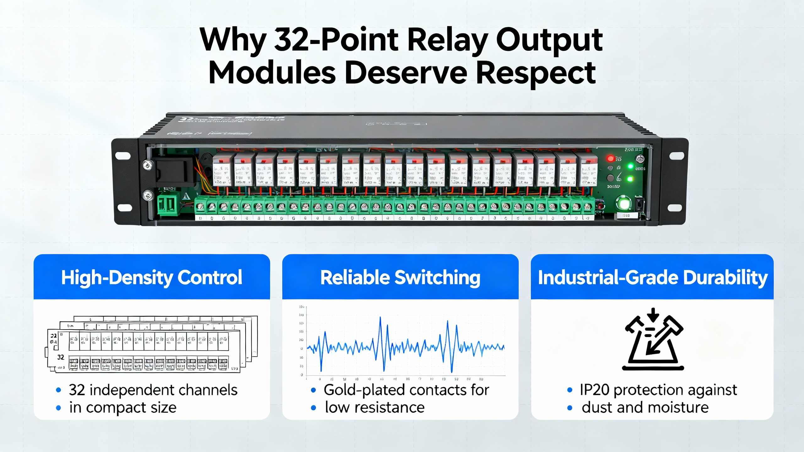
Why 32-Point Relay Output Modules Deserve Respect
In a drawing set, a 32-point relay output module often looks like an afterthought: one rectangle on the PLC rack with a part number and a few notes. On the shop floor and in the field, it is anything but trivial. Those 32 points are the last line between your control logic and real power. They are what actually switch motors, lamps, solenoids, dampers, and contactors on and off.
Over the years commissioning industrial lines, building automation panels, and utility controls, I have seen more downtime caused by misunderstood relay ratings than by firmware bugs. Contacts welded shut after a lighting retrofit. Outputs chattering on DC valves. “Dead” points that turned out to be fine electrically but too lightly loaded for the contact surface to stay clean.
The common pattern is simple. The module was “in spec” on paper when you looked only at the headline amperage. It was out of spec once you factored in inrush current, load type, duty cycle, ambient conditions, and the difference between AC and DC behavior. The relay application guides from companies like Omron, TE Connectivity, Finder, and others echo the same theme: understanding contact ratings is essential for real-world reliability, not a paperwork exercise.
In this article, I will walk through how to read and apply relay contact rating specifications for a 32-point output module, using principles drawn from those manufacturers and from field experience. The goal is not to turn you into a relay physicist. The goal is to give you a practical way to specify and apply these modules so they run for years, not months.
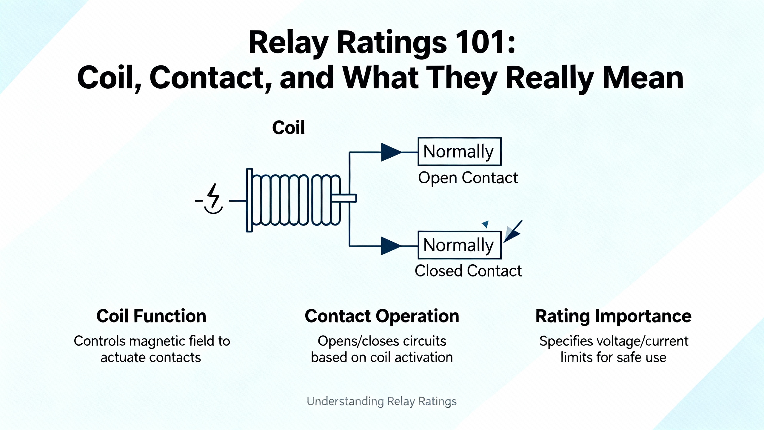
Relay Ratings 101: Coil, Contact, and What They Really Mean
Every relay on a 32-point output module has two distinct rating sets: coil ratings and contact ratings. Omron’s relay application notes stress this split, and it is the first place designers go wrong.
The coil side is on the control system’s turf. The module’s electronics drive that coil, not the field wiring, so you usually do not see the raw coil voltage in a PLC output module datasheet. In stand-alone relays, the coil has a rated voltage and (for AC) frequency that must never be exceeded or the relay will overheat, buzz, and eventually burn out. In modules, that same constraint applies inside the product. If you abuse the supply feeding the module or misapply AC vs DC variants, you are effectively overdriving many coils in parallel.
The field side is where contact ratings matter. Contact ratings specify the maximum voltage and current that the relay contacts can safely switch and carry, typically defined for a particular load type, such as “resistive.” Electronics engineers on forums and in manufacturer notes point out that there are at least three different limits hiding behind what looks like one number:
- There is a thermal or carry current rating that indicates how much current the closed contact can carry without overheating when nothing is switching.
- There is a breaking or switching capacity that tells you how much current and voltage the relay can interrupt at the instant of opening.
- There are sometimes separate ratings for inductive loads, motor (horsepower) loads, and minimum allowable loads.
On a 32-point module you may not see all those terms spelled out explicitly, but they are behind the vendor’s current and voltage numbers. For safe design you must respect the most restrictive of all stated limits, not just the largest number on the label.
Another subtlety is minimum load. Both Omron application guides and discussion from practicing engineers emphasize that contacts can fail at very low currents and voltages, not only at high ones. If the load is too small, oxide or contamination films are not broken down, contact resistance rises, and the circuit can behave intermittently. Datasheets sometimes call this the minimum low-energy permissible load: the minimum voltage and current needed to “wet” the contact reliably.
Put simply, on a 32-point relay output module, you must make sure each point is neither overloaded nor underloaded for the type of load it switches.
The Fine Print on Contact Ratings in a 32-Point Module
When you crack open a datasheet or catalog for a relay or output module, you will see a mix of terms like “10 A at 250 VAC (resistive),” “3 A at 30 VDC,” “rated thermal current,” and “insulation voltage.” These matter far more than their small font suggests.
Practitioners dissecting relay datasheets on engineering forums make a key distinction. Rated thermal current and insulation voltage describe how much current a closed contact can carry continuously and how much voltage the open gap can withstand without breakdown. They do not tell you what the contact can actually interrupt during switching. The real breaking capacity lives in the contact ratings table, usually broken out by AC vs DC and load type.
As an example from the literature, one relay is thermally comfortable carrying a certain current at a relatively high insulation voltage, but its DC breaking rating is limited to about 30 V DC and resistive loads only. The moment you put it on higher-voltage DC or inductive loads, you are outside the safe region, even if the general thermal number looks generous.
On a 32-point module, this means you cannot treat a single “per point current” as universal. You need to observe:
- The AC ratings, which may be listed for general-purpose loads and sometimes for motor or lamp loads.
- The DC ratings, which are nearly always lower in voltage and may restrict you to purely resistive loads.
- Any minimum load specification and any note about gold-plated or special contacts for small signals.
Many industrial output modules do not expose all of this detail on the quick-reference label, but it exists at relay level. Quality manufacturers explicitly test and document lifetime over multiple voltage and load conditions. Cheaper or generic modules often omit such curves altogether, which makes reliability hard to predict and should be a red flag for critical systems.
The practical rule, echoed in relay selection guides and practitioner advice, is that you size by contact ratings for the exact mode you intend to use: AC or DC, resistive, inductive, lamp, motor, and so on. You do not design from thermal or insulation ratings alone and you do not assume a linear relationship between current and lifetime.
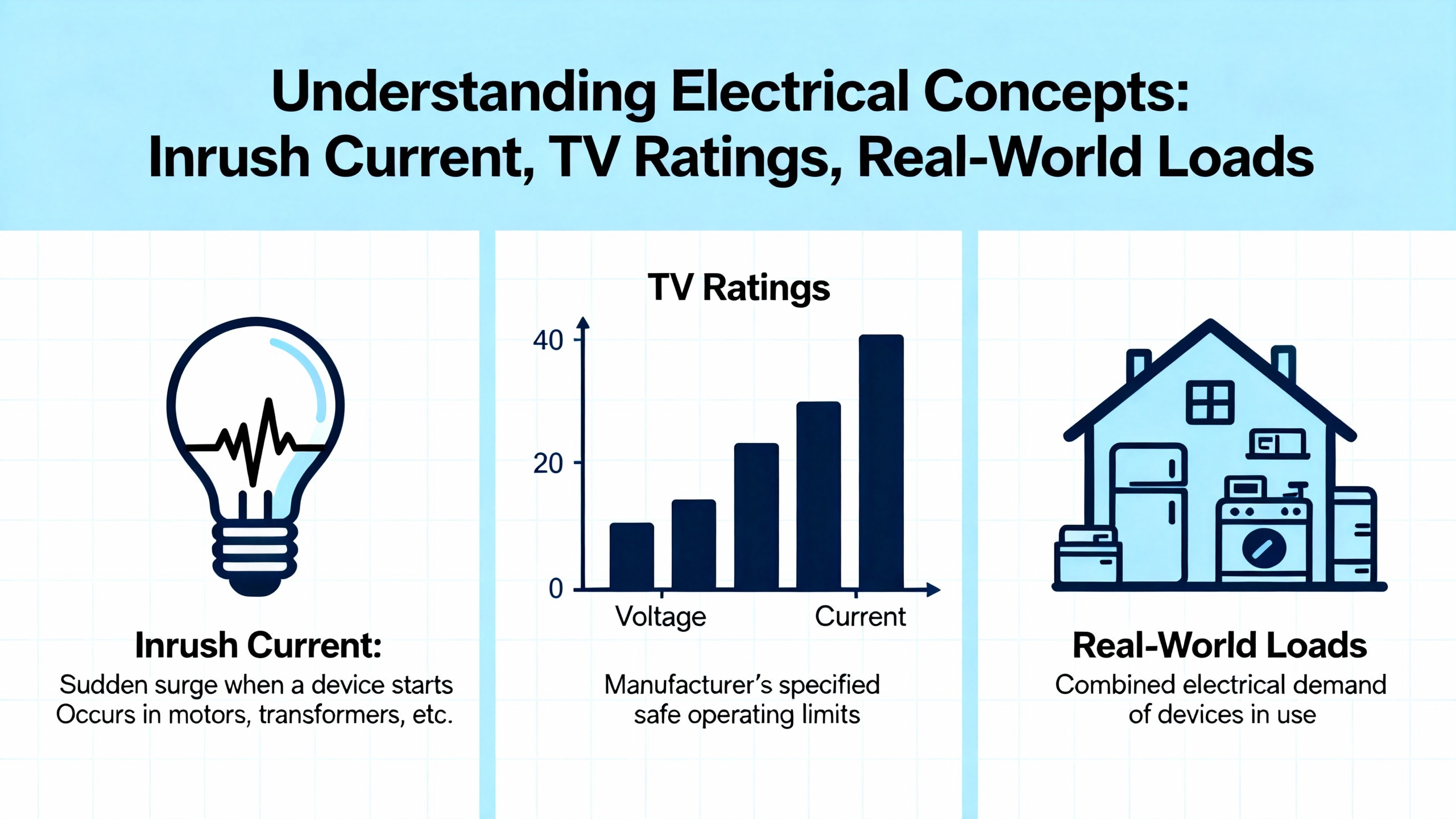
Inrush Current, TV Ratings, and Real-World Loads
The cleanest-looking contact rating tables assume resistive loads. Most field loads are not purely resistive. They have inrush.
Inrush current is the large, instantaneous current that flows when power is first applied. Omron’s application notes highlight incandescent lamps and motors as classic examples. A tungsten lamp can draw about ten times its steady-state current immediately after turn-on before settling down. In relay qualification, the TV (tungsten) rating defined by UL and CSA measures how well a relay survives that punishment. TV-3, TV-5, TV-8, TV-10, and TV-15 ratings correspond to combinations of enormous inrush currents with more modest steady currents. For example, a TV-10 relay is tested to tolerate about 141 A of inrush for a 10 A steady load through 25,000 switching operations on a tungsten lamp.
Azatrax’s guidance on relay contact current ratings drills this into a simple design rule for incandescent lamps: keep the lamp’s normal operating current to no more than one eighth of the contact’s rated current. They give a concrete example: with a 0.5 A rated contact, the lamp it switches should draw no more than 0.062 A in normal operation. That is not because the contact cannot carry more current resistively; it is because the inrush at turn-on will otherwise be large enough to erode or weld the contact prematurely.
On a 32-point output module, this has two direct implications. First, you cannot treat the module’s “per point” current rating as a blanket number for every load type. If a datasheet says 2 A per point at 250 VAC resistive, and you use that point to switch an incandescent lamp or a transformer primary, the effective safe continuous current for long life is much lower because the inrush is so much higher. Second, you need to think about simultaneous inrush. When an automation routine energizes an entire bank of lighting or multiple motor starters at once, you multiply the stress across many contacts and on the module’s internal buses.
A simple, practical approach is to map each load type on the module to a current derating strategy similar to what Azatrax and others describe and design the sequence so not every high-inrush load turns on at exactly the same millisecond. Time delay relays, soft-start functions, or staggered logic can greatly reduce peak stress on a dense output module.
For loads like LED lighting with proper current limiting, the situation is more forgiving. Azatrax points out that LED circuits, where current is controlled by a series resistor or driver, are not subject to the same filament inrush as incandescent lamps, so the contact can often use the full resistive rating. That does not remove the need to honor voltage, DC limits, or surge suppression for capacitive drivers, but it is a more gentle class of load.
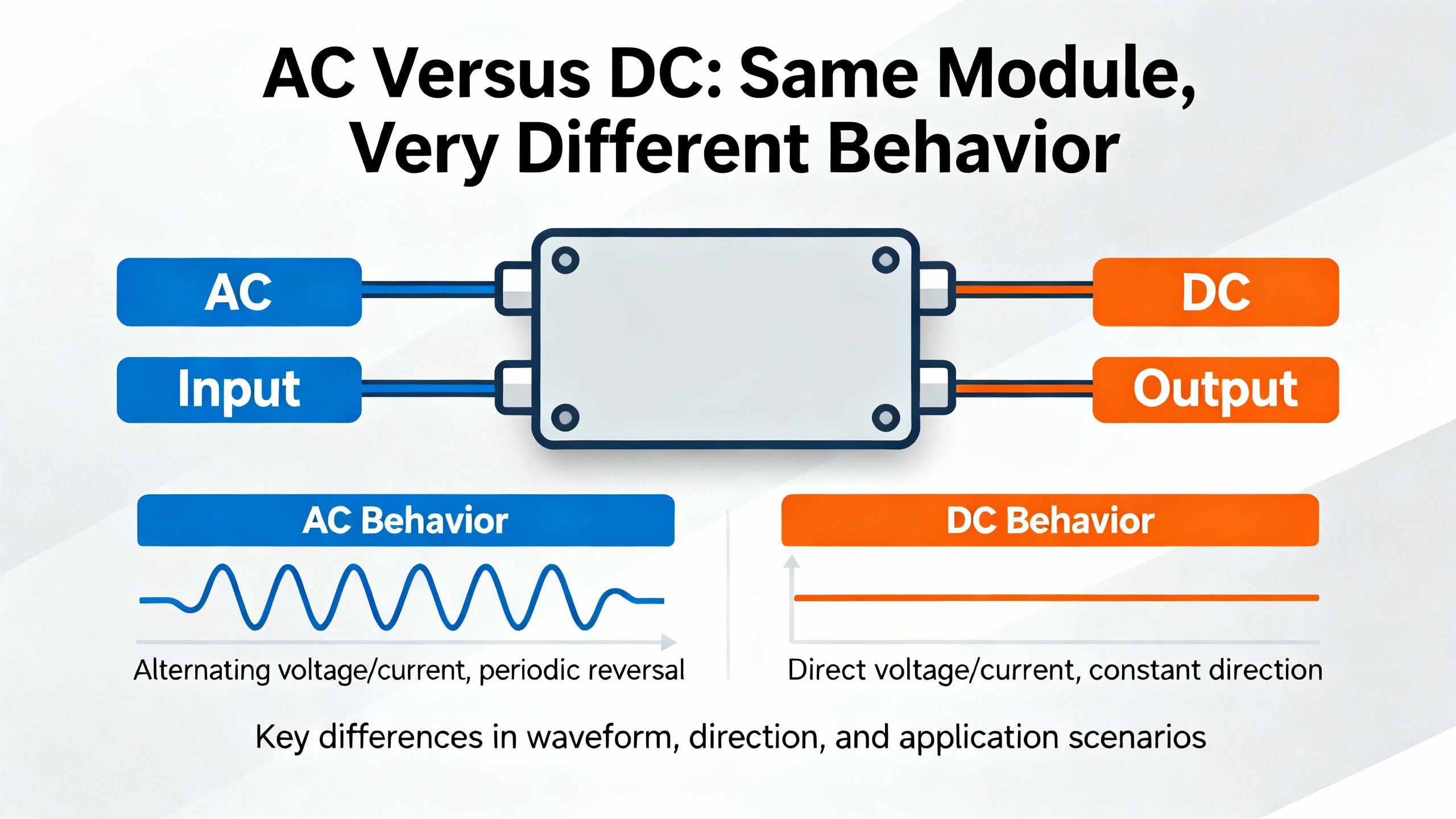
AC Versus DC: Same Module, Very Different Behavior
A contact that behaves politely on AC can behave brutally on DC. Both Omron’s notes and engineering forum discussions emphasize this.
In AC circuits, current crosses zero twice every cycle, one hundred or one hundred twenty times per second in typical mains systems. That natural zero crossing helps extinguish arcs when a relay opens. In DC circuits there is no such zero crossing. Once an arc forms, it sustains as long as voltage and current support it, which means longer arc duration, more energy, higher contact erosion, and a greater risk of welding.
Because of this, many relays and relay modules show generous AC ratings and very conservative DC ratings. It is common to see significantly lower maximum DC voltage than AC voltage even when the thermal capabilities of the contact metal are identical. In some documented cases, the relay is explicitly limited to low-voltage DC and to resistive loads only. Using that same contact on higher-voltage or inductive DC without mitigation is an invitation to welding and early failure.
Designers sometimes try to compensate by putting contacts in series to increase the effective gap and improve arc control. Omron notes this as a valid technique in DC applications: using contacts in series increases arc length and can reduce damage. In a 32-point module, you are usually not free to rewire internal contacts in series, but you might configure two points externally in series for a critical DC load, at the cost of using two outputs per device. That kind of design choice should be grounded in the module’s actual DC ratings and in test data, not in guesswork.
Another DC-specific concern is long-term closed operation. Practitioners on the Arduino forum report that DC relays which remain closed for weeks or months can suffer metal migration and weld shut so they will not open when called upon. A practical mitigation is to design the system so the relay opens periodically, even briefly, which is easier to do in software when you control the outputs of a PLC or controller.
On a 32-point module with mixed AC and DC outputs, the conservative rule is straightforward. Treat each DC load as a special case. Check the vendor’s DC contact ratings explicitly. Add arc suppression across inductive loads. Do not assume that because “it worked in the lab” at low switching frequency, it will survive years of field duty.
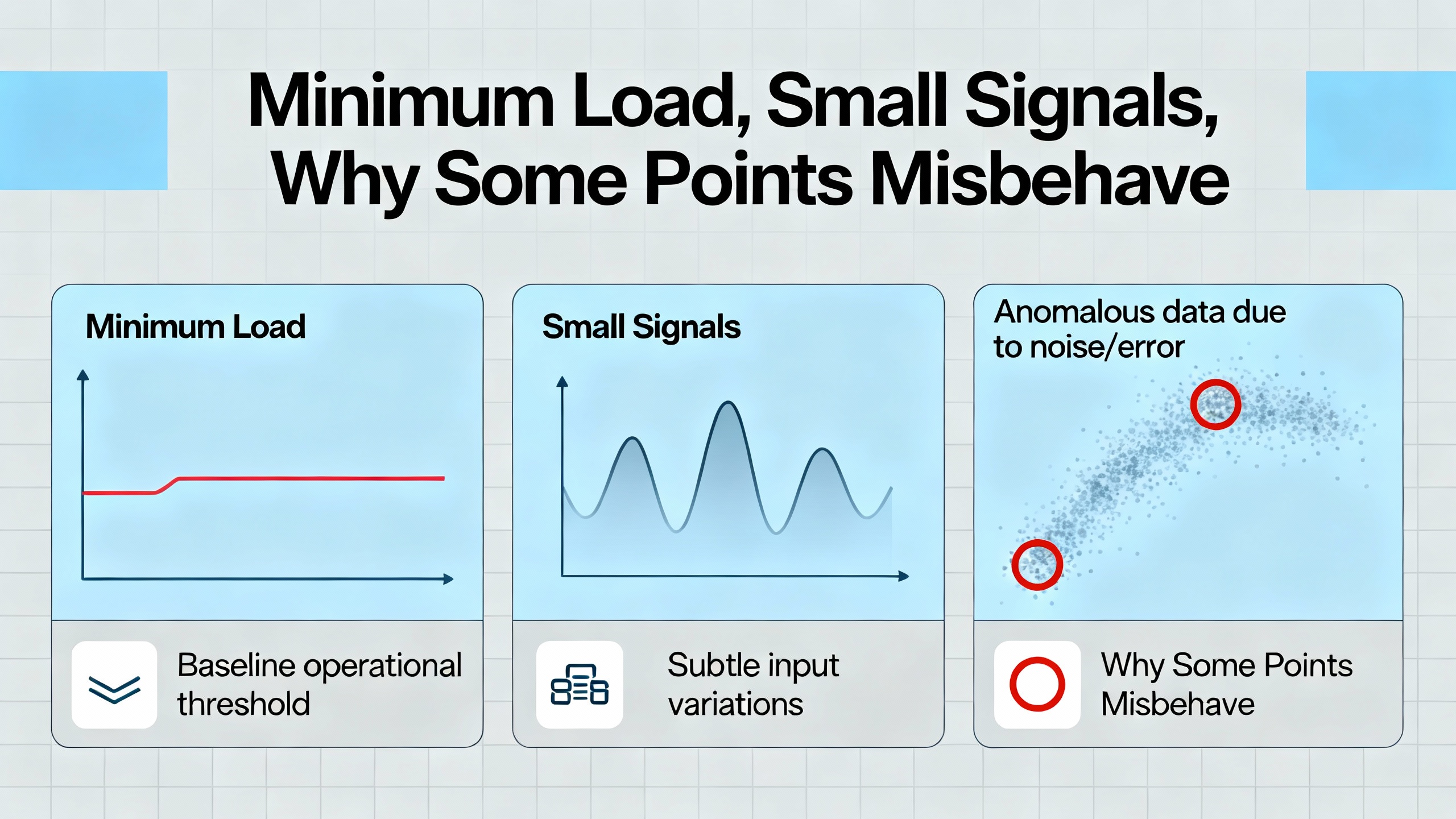
Minimum Load, Small Signals, and Why Some Points Misbehave
Most engineers worry about how much current they can put through a contact. Fewer worry about how little current they can put through it. Omron and others are explicit that minimum-load behavior matters, especially for minute signals.
At very low voltages and currents, the contact surfaces never see enough energy to break through oxide films or contamination. Contact resistance drifts upward, sometimes to the point where the signal is attenuated or the logic on the receiving end misreads the state. That does not show up as a catastrophic failure; the relay still “clicks” and continuity may measure correctly at high test voltages. Under actual operating conditions, however, the circuit can become unreliable.
To characterize this, relay suppliers define minimum permissible loads and quote minute-load failure rates as “P levels” at around 60% reliability, using standards such as JIS C5003. The key takeaway from those figures is not that the numbers are precise guarantees; in fact, the manufacturers caution that catalog values are indicative and must be verified in the real application. The key takeaway is that low-level switching is a different design regime than power switching and may need different contact materials or geometries such as twin contacts.
On a 32-point relay output module, minimum load issues surface when you use a power-type contact to switch tiny analog signals, very low-current logic, or PLC inputs instead of loads. For these cases, many practitioners recommend using relays with gold contacts or dedicated signal relays, or keeping a small “wetting” current in the path so the closed contact does real work. In other words, do not assume that because the module can switch a few amps it will automatically be happy switching microamp signals.
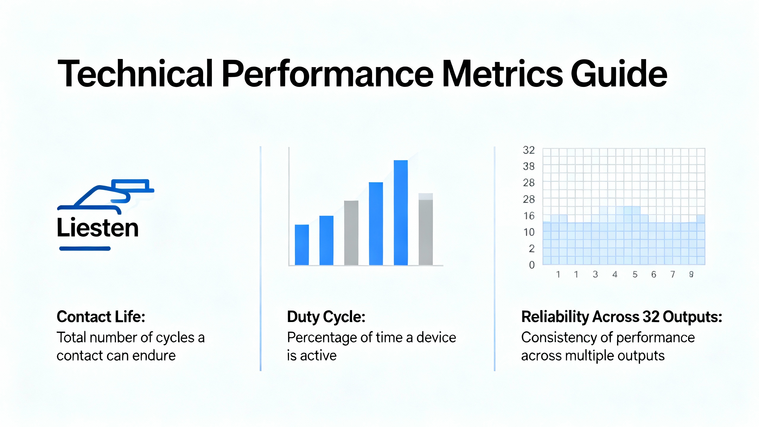
Contact Life, Duty Cycle, and Reliability Across 32 Outputs
Relay durability is not a single number. Omron, TE Connectivity, and several practical sources describe it as the combination of mechanical life and electrical life. Mechanical life is how many operations the relay can perform with no load; electrical life is how many operations it can perform under specified load conditions before its characteristics drift out of spec.
Electrical life depends on I²R heating as contacts carry current, arcing when they open, and material transfer between contacts. TE’s analysis of contact life explains how, as contacts begin to separate under load, the contact area shrinks, temperature rises, and metal may melt or even boil locally. Material splatters and migrates under the influence of temperature gradients and arcs. Surprisingly, some arcing is beneficial because it burns off films and keeps the surface clean; too little arcing in minute-load situations can lead to contamination build-up, while too much erodes the contact.
In their example, a relay switching 40 V at 2 A might achieve roughly 300,000 operations, but that figure is tied to specific conditions. In the real world, switching frequency, ambient temperature, humidity, and the nature of the load can move the number up or down significantly.
When you stuff 32 relays into one output module, lifetime issues aggregate in a very practical way. Some points may almost never switch; others may chatter all day under a high inrush load. The average “per contact” lifetime in the catalog is less important than the lifetime of the worst-stressed point in your application.
Engineers on practitioner forums point out that low-cost relays and boards often omit any meaningful lifetime data, which makes design by specification impossible. In industrial and communications equipment, contributors consistently recommend relays from reputable manufacturers and distributors. The reason is simple: quality parts come with tested lifetime curves across several operating conditions. Cheap parts may work in the lab but fail unpredictably in service.
For a 32-point output module that must be a long-term asset, the pragmatic path is to:
- Avoid assuming that a relay that works initially is reliable indefinitely.
- Select modules that publish clear electrical durability data and test under loads similar to yours.
- Treat inrush-heavy points and high-frequency points as special and allocate higher-rated outputs or dedicated relays to them.
- Consider periodic exercising of DC outputs that remain closed for long periods to mitigate welding from metal migration.
From a system integrator’s perspective, this is less about pedantic component selection and more about predictable maintenance windows and less unscheduled downtime.
Contact Materials and High-Inrush Applications
Contact material is one of those details that engineers know matters but rarely dig into until they have a failure. Finder’s discussion of contact materials for industrial relays gives a concise overview that is directly relevant for high-density output modules.
For power relays handling up to roughly 50 A, commonly used contact materials include silver nickel (AgNi), silver cadmium oxide (AgCdO), and silver tin oxide (AgSnO₂). Silver nickel is a true alloy with around ten percent nickel. The nickel hardens the silver and improves resistance to electrical erosion, which makes AgNi a robust, general-purpose choice for resistive loads and moderate surges.
Silver cadmium oxide has been a workhorse material for decades because it performs very well on inductive and motor loads, especially under short, high inrush conditions such as contactor coils, incandescent lamps, and small motors. However, cadmium is restricted by environmental regulations, and manufacturers are phasing out AgCdO contacts under RoHS-type constraints.
Silver tin oxide is a cadmium-free alternative produced by powder and sintering techniques. Early versions had inconsistent behavior, but modern manufacturing yields AgSnO₂ contacts that equal or beat AgCdO performance in many high-inrush applications. Finder notes that AgSnO₂ is particularly effective where capacitive loads dominate, such as power factor correction capacitors or the input stages of certain fluorescent and LED drivers. The problem with capacitive loads is the lack of deliberate current limiting. Instantaneous inrush is limited only by source and line impedance and can reach several hundred to several thousand amperes.
For a 32-point output module, you typically do not get to choose the contact material for individual points; the module is built with one relay family. But you do get to choose which module family you specify for a given project. If you know that a bank of outputs will drive capacitive or lamp loads with brutal inrush, it is worth favoring modules whose relays use AgSnO₂ contacts or are otherwise documented as high-inrush capable. That information often lives in the relay manufacturer’s literature, not just in the catalog listing.
The practical message is that contact material is a real lever on reliability in high-inrush scenarios. You do not need to be a materials scientist, but you do need to match the module’s contact technology to the dominant load style on those 32 points.
Environment, Panel Layout, and Heat Management
Relays are tested under defined environmental conditions. Qianji’s sizing guidance, for instance, notes that many relays are specified around a temperature range of roughly 15–35°C, which corresponds to about 59–95°F, and a relative humidity between about 25% and 75%. Push hardware beyond those comfort zones and you accelerate aging.
High temperature increases coil heating and contact resistance, dragging the relay toward its thermal limits. High humidity, especially with pollutants like sulfur compounds, can corrode contacts and contribute to film formation that affects minimum-load behavior. Rapid temperature swings encourage condensation, which is bad news for insulation and for plated surfaces. Vibration and shock can mechanically misalign or damage internal parts, leading to chattering, buzzing, or intermittent operation.
In a dense 32-point module mounted in a control panel or rack, the relays are physically close. Heat from one load path can warm neighbors, and the module sits in whatever microclimate your enclosure provides. Simcona’s relay selection guidance calls out physical size, mounting, and operating environment as core factors in selection. Smaller relays support higher density but can make heat dissipation harder in miniature assemblies. DIN-rail modules may be tightly clustered, further challenging cooling.
From a system design standpoint, you have more levers than you might think. You can place high-load modules where panel airflow is better. You can respect horizontal spacing guidelines from the PLC vendor rather than packing every slot. You can avoid mounting heat-generating power supplies directly beneath densely loaded output cards. These are not cosmetic choices; they materially influence temperature rise at the relay and therefore contact life.
Environmental sealing also matters. Open-frame relays and cheap sealed versions can accumulate dust or contamination inside over time. Practitioners report seeing debris weld contacts together even on supposedly sealed “cube” relays. For long-term, dependable operation, especially in dusty or chemically aggressive environments, it is wise to favor modules built with relays from reputable manufacturers and with sealing appropriate to the environment.

A Practical Specification Workflow for a 32-Point Relay Output Module
Putting all of this together, let me describe a practical, repeatable way to specify and apply a 32-point relay output module as a project partner would, based on principles echoed in guides from Qianji, Simcona, Omron, and others.
First, gather real load data. Do not just ask, “What voltage?” Ask what each point is actually switching: heaters, solenoids, motor starters, incandescent or LED lighting, analog signals, or logic inputs. For each type, determine the nominal voltage, the worst-case steady current, and whether there is known inrush or inductive behavior. Where the data is fuzzy, assume the more demanding load type.
Next, map each load to the contact rating category. Resistive heaters fit the textbook resistive case. Motors, solenoids, contactor coils, and transformers sit in the inductive class. Incandescent lamps and certain capacitor-heavy circuits go into the high-inrush group. Very small analog or logic signals live in the minute-load class. This mapping tells you which rows of the relay or module datasheet matter for each point.
Then, apply a conservative current and voltage margin. Qianji’s recommendation is to choose relay ratings roughly twenty to thirty percent higher than the system’s maximum voltage and current. If your application draws 10 A in steady operation, you look for a module whose appropriate contact rating is in the 12–13 A range or higher for that type of load. This margin is not luxury; it is the headroom that absorbs inrush, supply variation, and environmental drift without driving the relay at the ragged edge.
At the same time, honor DC limits carefully. If the module’s contact table says the relay is only rated for 30 V DC resistive, take that seriously. For higher-voltage DC or for inductive DC loads, consider either a different module family rated appropriately, external relays in series, or a different switching technology like solid-state outputs. The oversizing margin does not allow you to violate DC voltage limits.
Now, consider lifetime and duty cycle. Use any available durability curves to check that the expected number of operations at your load conditions sits in a comfortable region. If you expect a particular output to operate many times per minute on a harsh inductive load, do not assign it arbitrarily to the cheapest module in the rack. Either allocate a higher-rated card or move that function to a dedicated relay. Remember that overall system reliability is set by the most abused point in the array, not the average.
After that, evaluate environment and heat. Review the panel’s ambient temperature range and humidity against the relay’s specified environment. If the panel will see hotter than about 95°F for long periods, or considerable vibration, treat that as derating. Spread high-load modules so they are not all in the hottest location. Consider forced ventilation or panel cooling if you are stacking several fully loaded 32-point modules in one enclosure.
Then, address surge and arc suppression. For DC coils and inductive loads, include flyback diodes or equivalent suppression as Azatrax and automotive guides recommend. For AC inductive or capacitive loads, use appropriate snubbers or transient protection. TE and other vendors clearly show that arc suppression is one of the most effective tools for extending contact life and reducing material loss. On a 32-point card, good suppression improves not just individual relays but module-wide noise and stress.
Finally, plan for maintenance and diagnostics. Because relays do fail, design your I/O maps in a way that makes point reassignment straightforward. Group similar loads where possible. Make sure the controller has diagnostics for outputs that fail to energize or release, and document which points are carrying the heaviest inrush and duty. This is where your experience as an integrator pays off. You can guide the client toward a panel layout and spares strategy that matches how the module will actually be used, not just how it looked on the first drawing.
For quick reference, it can help to think in terms of a few core design axes, as summarized in the table below.
| Design axis | What you check | Why it matters on 32 points |
|---|---|---|
| Voltage and current | Load voltage, steady current, required margin | Prevents overheating and respects breaking capacity |
| Load type | Resistive, inductive, lamp, capacitive, minute-load | Determines inrush behavior, DC stress, and minimum load concerns |
| AC versus DC | Rated AC and DC limits for contacts | DC arcs and inductive DC loads can destroy AC-optimized contacts |
| Lifetime and duty cycle | Expected operations per day and switching frequency | Protects the most heavily used points from premature wear |
| Environment and heat | Ambient temperature, humidity, vibration, panel airflow | Avoids pushing internal relay temperatures beyond tested conditions |
| Contact material | AgNi, AgSnO₂, or other power-contact materials | Influences welding risk in high-inrush and capacitive applications |
| Surge suppression | Diodes, snubbers, MOVs at loads and coils | Reduces arcing, EMI, and contact material loss |
Treat those as the dials you can adjust when you select and apply a 32-point module rather than as paperwork fields to fill in once.
FAQ
Can I use a 32-point relay output module that is “AC rated” to switch DC loads?
Yes, but only if the datasheet explicitly gives DC ratings that cover your operating voltage and load type. Manufacturer guidance and practical experience both stress that DC arcs are harder to extinguish than AC arcs, so the safe breaking voltage and current on DC are usually much lower than for AC. Some relays are limited to low-voltage DC and resistive loads only. Never assume an AC general-purpose rating applies unchanged to DC.
Why do some lighting or capacitor banks destroy relay outputs so quickly?
Incandescent lamps and capacitive inputs are classic high-inrush loads. When power is applied, they can draw many times their steady-state current for a brief period. Omron’s TV ratings and Azatrax’s inrush guidelines show that this inrush, not the steady current, often dominates contact wear. If you size purely by the steady current, you under-protect the relay. The fix is to either derate the contact current drastically for lamp and capacitive loads, use relays with high TV or AgSnO₂ contact technology specifically qualified for that behavior, or add measures like inrush limiting and staggered start sequences.
How many points can I safely load to the full rated current at the same time?
This is a question that cannot be answered generically, and responsible manufacturers avoid promising that every point can be run at the headline rating simultaneously under all conditions. The effective answer depends on internal bus design, thermal paths, ambient temperature, and the duty cycle of each point. Relay selection and application guides recommend using the published thermal and current ratings as per-point maxima, then applying engineering judgment and, ideally, testing when you expect many points to run near that limit together. In conservative industrial practice, it is common to avoid operating every point at the ceiling rating continuously, especially in hot or cramped enclosures.
Closing Thoughts
A 32-point relay output module is not just a dense row of switches. It is a cluster of electromechanical devices whose behavior is governed by contact physics, inrush currents, arc dynamics, materials, and environment. When you respect those realities, drawing on the kind of guidance provided in manufacturer application notes and reinforced by field experience, these modules will quietly do their job for years. When you ignore them and design only to the boldest number on the label, you push the burden onto the maintenance team and, ultimately, the plant.
As a systems integrator, my role is to be the partner who worries about these details so owners and operators do not have to. If you treat contact ratings on your 32-point output modules as first-class design parameters rather than fine print, you will see the payoff in cleaner startups, fewer welded contacts, and a control system your team trusts.
References
- https://www.academia.edu/Documents/in/Relay_Coordination
- https://staff.najah.edu/media/published_research/2024/09/07/energies-16-05328.pdf
- https://www.azatrax.com/relay-contacts.html
- https://relaypros.com/choosing_proper_amperage.htm?srsltid=AfmBOoo03ifS9O4Ok2hqSCCcpQts2N_qPekORe3lM-MMeH2AnjFW7aCT
- https://www.swe-check.com.au/editorials/understanding_relays.php
- https://www.microchipusa.com/electrical-components/how-does-a-relay-work-a-complete-guide?srsltid=AfmBOopCwI5hNRgK6Vlhm1gLF8C24LPz3enYK2yEy-8XPLN2vvjfIPw-
- https://na.noark-electric.com/relay-contact-ratings-nema-ics5-2017/
- https://www.qianji-relay.com/info/how-to-determine-the-correct-relay-size-for-yo-102956031.html
- https://simcona.com/blog/relay-selection-guide
- https://forum.arduino.cc/t/relay-current-rating/616907
Keep your system in play!
Top Media Coverage
Categories


Related articles Browse All
-
 amikong NewsSchneider Electric HMIGTO5310: A Powerful Touchscreen Panel for Industrial Automation2025-08-11 16:24:25Overview of the Schneider Electric HMIGTO5310 The Schneider Electric HMIGTO5310 is a high-performance Magelis GTO touchscreen panel designed for industrial automation and infrastructure applications. With a 10.4" TFT LCD display and 640 x 480 VGA resolution, this HMI delivers crisp, clear visu...
 -
 BlogImplementing Vision Systems for Industrial Robots: Enhancing Precision and Automation2025-08-12 11:26:54Industrial robots gain powerful new abilities through vision systems. These systems give robots the sense of sight, so they can understand and react to what is around them. So, robots can perform complex tasks with greater accuracy and flexibility. Automation in manufacturing reaches a new level of ...
 -
 BlogOptimizing PM Schedules Data-Driven Approaches to Preventative Maintenance2025-08-21 18:08:33Moving away from fixed maintenance schedules is a significant operational shift. Companies now use data to guide their maintenance efforts. This change leads to greater efficiency and equipment reliability. The goal is to perform the right task at the right time, based on real information, not just ...


- Q&A
- Policies How to order Part status information Shipping Method Return Policy Warranty Policy Payment Terms
- Asset Recovery
- We Buy Your Equipment. Industry Cases Amikong News Technical Resources Why choose us
- ADDRESS
-
 32D UNITS,GUOMAO BUILDING,NO 388 HUBIN SOUTH ROAD,SIMING DISTRICT,XIAMEN
Leave Your Comment