
-
Please try to be as accurate as possible with your search.
-
We can quote you on 1000s of specialist parts, even if they are not listed on our website.
-
We can't find any results for “”.
Allen-Bradley 1769-L33ER CompactLogix Manual: Installation and Programming Guide
Why the 1769-L33ER Still Matters
Viewed from the shop floor, the Allen-Bradley 1769-L33ER is not just a catalog number. It is a CompactLogix 5370 L3 controller that shows up in real machines: packaging lines, small process skids, material-handling cells, and building systems. It sits in a row of 1769 I/O modules, speaks EtherNet/IP to drives and HMIs, and quietly runs production for years—until someone mis-sizes the power supply, crams it into a hot enclosure, or rushes the programming.
This guide walks through how to treat the 1769-L33ER the way a veteran integrator does, using the structure of Rockwell Automation’s own manuals and field-proven best practices from resources such as the AutomationDirect control-system design guide, Control.com’s controller sizing primer, Industrial Automation Co’s CompactLogix 5370 fault guide, and practical tutorials from SolisPLC and Maple Systems.
You should treat Rockwell’s official documents—especially the 1769-series installation instructions and user manuals such as publications 1769-IN023, 1769-UM007, and 1769-UM011—as the authoritative reference for exact ratings, torque values, and configuration steps. The goal here is to help you read those manuals with the right mental model and avoid the failures that show up later on nights and weekends.
Where the 1769-L33ER Fits in the CompactLogix Family
The 1769-L33ER is part of the CompactLogix 5370 L3 family that uses 1769-series modular I/O. From the perspective of system architecture, it is a modular programmable automation controller, not a small fixed “brick” PLC. That distinction matters.
Fixed or micro PLCs tend to bundle CPU and I/O into a single housing with little or no expansion. They are cheaper and fit very small systems, but they quickly run out of I/O, memory, or communication options. Modular platforms like CompactLogix let you snap power supplies, controllers, digital and analog modules, specialty I/O, and communication modules onto a backplane to match the system’s needs and expand later.
A CompactLogix 5370 controller like the 1769-L33ER is typically used where you need more structure than a MicroLogix-style unit can provide, but do not need the full scale of a ControlLogix chassis. Think mid-sized machines and skids that may grow over time, where EtherNet/IP is the primary fieldbus and you want a standard Rockwell Automation toolchain and tag-based programming.
At a high level, you can think about the L33ER this way:
| Aspect | What It Means In Practice |
|---|---|
| Controller family | CompactLogix 5370 L3, tag-based controller programmed with Studio 5000 Logix Designer. |
| Local I/O system | Uses 1769 modular I/O, mounted directly beside the controller on a common backplane. |
| Network orientation | Designed for EtherNet/IP; integrates well with drives, HMIs, and IO over Ethernet. |
| Typical applications | Machine-level and small system control such as packaging cells, conveyors, and skids. |
| Integration ecosystem | Fits into Rockwell-centric architectures that also use MicroLogix, ControlLogix, and HMIs. |
The official Rockwell datasheets and user manuals will tell you the exact memory size, maximum number of local I/O modules, and supported connection counts. Instead of repeating those numbers here, this guide focuses on how to plan, install, and program in a way that respects those limits and avoids surprises.
Plan Before You Mount or Wire Anything
Experienced integrators spend more effort up front on specification and design than on typing ladder logic. The AutomationDirect “Automation Control System Specification, Design and Installation Guide” and Control.com’s controller sizing primer both stress the same pattern: safety and scope first, then I/O and networks, then hardware. The 1769-L33ER is no exception.
Safety, Standards, and Qualification
The first reality check is whether you and your team are qualified to design and install an industrial control system. As AutomationDirect’s guide and related PanelBuilder articles emphasize, a poorly designed system can cause serious injury, fire, or equipment damage. If you are not already fluent in basic electricity, NFPA and NEMA standards, lockout/tagout, and industrial safety, partner with a qualified system integrator and treat the manuals as training material, not permissions.
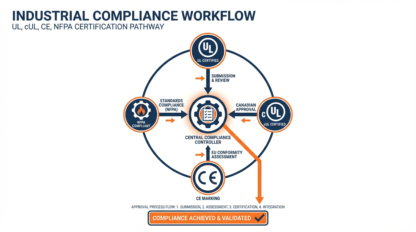
You should design and install the 1769-L33ER system in compliance with applicable local, state, and national codes and standards. Commonly referenced frameworks include NFPA fire codes, the National Electrical Code, NEMA standards for enclosures and industrial controls, and OSHA rules for lockout/tagout of hazardous energy. Many applications also require components with specific UL, cUL, or CE markings. Those agency requirements should be captured early, because they strongly constrain which controllers, I/O modules, and other devices you can use.
Lockout/tagout is particularly important. Guidance from automation safety articles stresses that automated systems must be designed so that all energy sources—electrical, pneumatic, hydraulic, and mechanical—can be safely isolated during service. Emergency stops should be clearly labeled and wired so they remove hazardous power, using appropriate electromechanical safety devices independent of the PLC outputs.
Identify What You Are Automating
Before you worry about which slot the 1769-L33ER will occupy, you need a clear picture of the process and equipment it will control. Control.com’s beginner’s guide to automation suggests starting with a simple flowchart of the process and then building a detailed I/O list, and that method works very well in practice.
For each device and function, decide whether the PLC sees it as an input or an output, and record signal type and electrical details. Distinguish digital and analog points, motion-related feedback, discrete sensors such as limit or proximity switches, and communication-based devices such as drives on EtherNet/IP. Typical digital levels in industrial systems are often 24 VDC, and common analog ranges include 4–20 mA current loops and 0–10 V signals. Record whether each device is sinking or sourcing so you can match I/O card type and wiring correctly.
A disciplined way to do this is to build a spreadsheet with columns for tag name, description, signal type, voltage or current, physical location, and panel terminal.
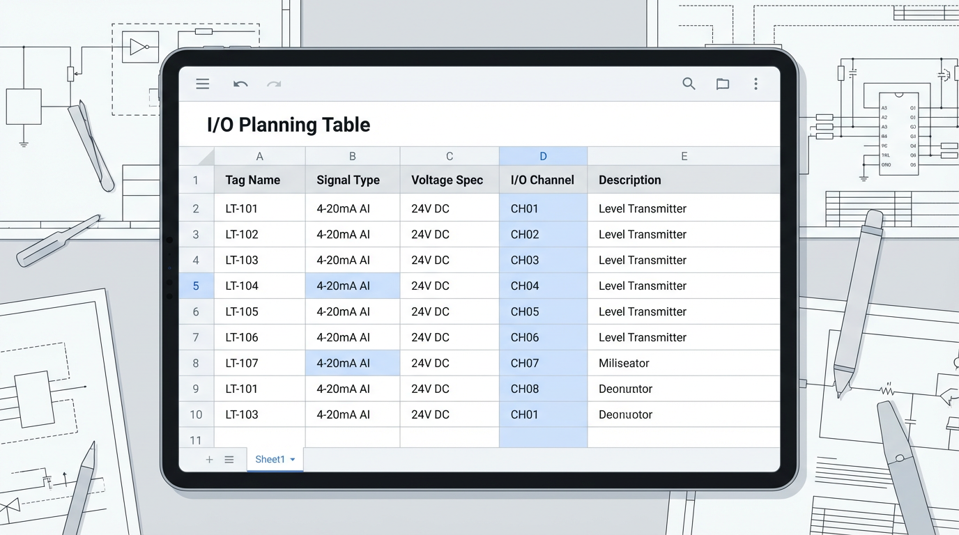
That spreadsheet becomes your reference when you configure 1769 modules in the L33ER project and when you commission the system.
Size I/O and Leave Room for Growth
Newer engineers often size their CompactLogix systems for exactly the number of points they see on day one. That is a mistake you only make once. Both Control.com and AutomationDirect guidance recommend explicitly planning for expansion. As a starting rule of thumb, aim to have at least several spare I/O points of each type and enough panel space for at least a couple of extra 1769 modules.
Digital 1769 I/O modules typically come in common densities such as eight, sixteen, or thirty-two channels. Consider not just the count, but whether you need relay outputs for isolation and flexibility or solid-state transistor outputs for speed and life. Motion feedback and high-speed counting often require dedicated high-speed I/O cards; if you will be using encoders, make sure the modules and controller scan strategy can support the required pulses-per-revolution and quadrature resolution described in standard PLC glossaries.
Choose Network Architecture Intentionally
CompactLogix 5370 controllers like the L33ER live most comfortably on EtherNet/IP, and that is usually the default choice for I/O adapters, drives, and HMIs in Rockwell-centric plants. Fieldbus choices are often dictated by device compatibility: many Rockwell devices ship with EtherNet/IP, while equipment from other vendors may use PROFIBUS, IO-Link, or other protocols.
Control.com’s survey of fieldbus options notes that a single EtherNet/IP network can typically support on the order of a couple hundred nodes. That does not mean you should push every system to that limit, but it does mean you can comfortably integrate drives, safety devices, and remote I/O around a L33ER if you design the IP addressing and switching properly.
Where building or campus standards exist—such as the University of Connecticut’s building automation standards that demand open protocol BAS networks—you will want to align the CompactLogix choice and network layout with those standards, ensuring that any higher-level BAS or SCADA can talk to the controller cleanly using open protocols.
Installation Essentials for the 1769-L33ER
Once planning is in place, the physical work begins. The official Rockwell installation instruction for the 1769 family (for example, publication 1769-IN023 for certain modules) is your step-by-step checklist for mounting, spacing, wiring, and grounding. What follows are the patterns that keep those instructions from being misinterpreted in the field.
Enclosure, Mounting, and Thermal Management
AutomationDirect’s design guide emphasizes selecting NEMA- or IEC-rated enclosures appropriate to the environment. For a 1769-L33ER system, that means thinking ahead about the full row of 1769 modules, power supplies, network switches, and auxiliary devices that will share the panel. You want enough space not only for what is there today, but also for the two or three modules someone will inevitably add later.
Thermal management is not an afterthought. The guide recommends ensuring that devices operate within their rated temperature range, often by providing both cooling and, in some climates, heating inside the enclosure. Controllers that run hot day after day will fail early. For a CompactLogix system, that means leaving vertical space for airflow, respecting spacing guidelines in the manual, and specifying panel air conditioning or filtered fan packages where ambient temperatures justify them.
One subtle but important point from the same guide is maintenance access. Panels that are jammed into corners or packed so tightly that you cannot get a meter on a terminal invite unsafe workarounds. Provide adequate door openings, interior lighting, and a convenience receptacle so technicians can safely power laptops and test equipment during troubleshooting.
Power Supplies, Grounding, and Noise
On the power side, the AutomationDirect guidance is clear: size DC power supplies at roughly twice the calculated load. That rule of thumb, aligned with UL 508 expectations, keeps supplies running cooler and improves service life. It also gives headroom when additional 1769 modules or network devices are added later.
The 1769-L33ER and its associated I/O base will have specific voltage and current requirements documented in Rockwell’s literature. Rather than guessing, derive your supply sizing from the manual’s current draw figures per module plus the loads of any external devices fed from the same supply, then apply that two-times margin. Use separate supplies or at least separate grounding and wiring practices for noisy loads such as contactors and drives versus sensitive analog instrumentation.
Proper grounding serves two purposes: shock protection and noise control. The AutomationDirect and safety-focused guides emphasize a solid, common ground reference and correct bonding of panels and devices. They also warn that very low humidity (below roughly thirty percent relative humidity) increases electrostatic discharge problems, so in clean, dry rooms you may need to pay particular attention to anti-static flooring and ESD procedures when working inside panels.
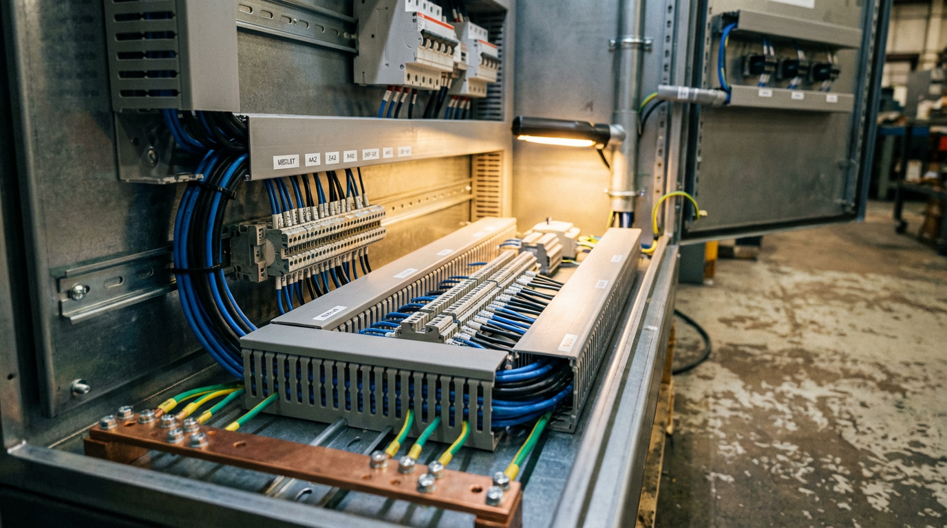
I/O and Field Wiring Practices
When you land field wiring on 1769 I/O modules, the project’s I/O spreadsheet should drive everything. Use it to confirm that each terminal’s voltage, wiring type, and signal type match the module definition and the program’s tag description.
Control.com’s article highlights several practical points that apply directly here. Make sure sinking and sourcing devices are matched to the right kind of input card and wired consistently. Select relay outputs where you need isolation or to handle mixed voltages, and transistor outputs where speed and life expectancy under frequent switching are more important. Reserve high-speed inputs for encoder or counter applications that genuinely need them; do not burn them on slow limit switches.
Keep low-level analog and communication wiring physically separated from high-voltage motor circuits and large contactors inside the panel to reduce noise coupling. Follow Rockwell’s shielding and grounding recommendations for analog modules, and use twisted-pair cable where appropriate.
Network and Communication Wiring
On network wiring, the SolisPLC tutorial on messaging between MicroLogix and CompactLogix controllers provides useful practical detail. For EtherNet/IP, you will configure each device with an IP address and use standard industrial Ethernet cabling through managed or unmanaged switches as appropriate. Inside Studio 5000, paths to remote devices specify hops through the backplane and out through an Ethernet interface, often beginning with an element that indicates both that backplane hop and the Ethernet path to the remote device.
In the real world, the troubleshooting advice in that tutorial is gold. Before you blame the controller or the program, make sure the network itself is sound.
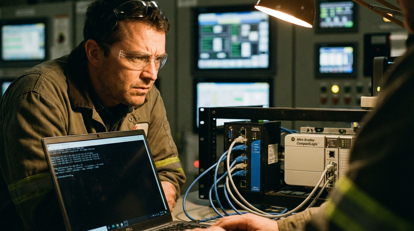
Put your engineering laptop on the same network segment and verify you can ping the L33ER and key devices. If simple ping fails, your configuration in Studio 5000 will not save you.
First-Time Programming and Start-Up
With hardware in place, you move into programming and commissioning. The basic process described in MRO Electric’s beginner’s guide to Allen-Bradley PLC programming applies: power the hardware, establish communications, create the project, map the I/O, and then build up logic in layers.
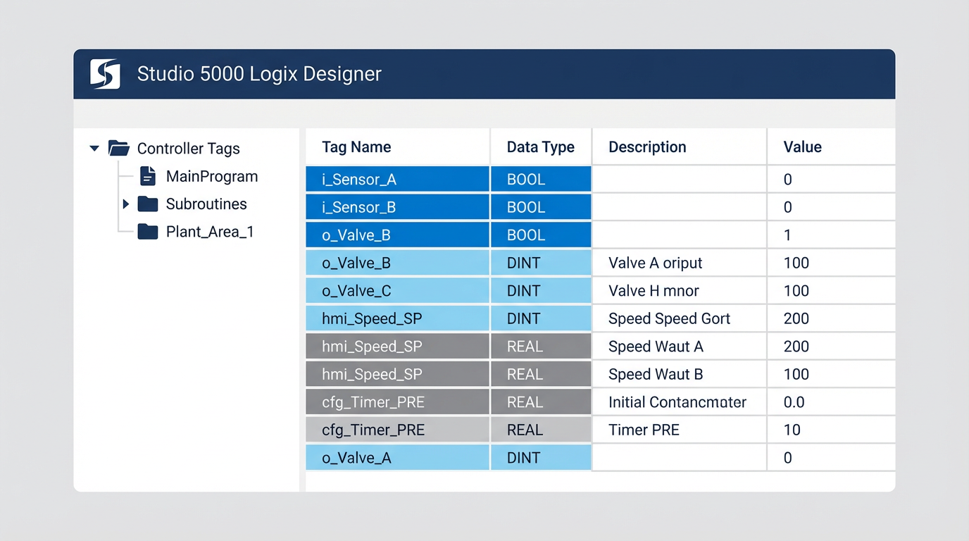
Tools, Project Creation, and I/O Map
Programming a 1769-L33ER requires Rockwell Automation’s Studio 5000 Logix Designer along with RSLinx as the communication layer between the PC and the PLC. Studio 5000 licensing is mandatory beyond any trial periods, so plan for that in your project budget.
When you create a new project, select the exact controller catalog number so Studio 5000 can enforce the correct limits and features. Then configure each local 1769 I/O module to match what is physically on the backplane, in the same order. This is where that I/O spreadsheet pays off again. Tag names should be meaningful and consistent, because they will show up not only in the logic but also in HMIs, SCADA systems, and maintenance procedures.
Ladder Logic Building Blocks You Will Actually Use
While the Logix family supports multiple languages, the majority of day-to-day logic around a CompactLogix 5370 is still written in ladder. The Automation Control System specification glossary explains the fundamental concepts in terms that align with how electricians think: rungs, contacts, and coils.
On-delay and off-delay timers are used constantly. An on-delay timer waits for its preset time before turning on; an off-delay turns on immediately and delays turning off. Retentive timers and coils preserve their state across interruptions, which is powerful but also dangerous if misused, because they can resume in unexpected states after power is restored. One-shot instructions give you a single-scan pulse, which is invaluable for incrementing counters or triggering one-time actions on a rising edge.
PID control, described in the same glossary, is what you use when you need to regulate temperature, flow, level, or speed rather than merely turning things on and off. In Rockwell systems, enhanced PID (PIDE) instructions are often used for more complex loops. An Ignition forum discussion among practitioners highlights a practical lesson: operators and HMIs usually care only about process variable, setpoint, and output, while most configuration parameters are rarely touched. Expose those key tags cleanly, and consider mapping the rest into a compact user-defined type that SCADA systems can read efficiently.
Sharing Data Between Controllers with MSG
The SolisPLC tutorial on MSG instructions between a MicroLogix 1100 and a CompactLogix L24ER is directly relevant if your L33ER needs to talk to another controller. The essential pattern is to use a timed ladder structure to trigger MSG instructions at sensible intervals, rather than continuously.
A typical rung uses a repeating timer and a comparison instruction so the MSG executes once per timer cycle.

In the MSG configuration, you specify whether you are doing a read or write, the remote data address and type, the local tag that will hold the data, and the communication path that describes how to reach the remote PLC over EtherNet/IP.
Two practical recommendations from that tutorial are worth repeating. First, do not send MSGs more often than your process actually needs; excessive messaging can congest the network and load the controller. Second, treat MSG-based communications as non-deterministic. The delivery time can vary with network conditions, so for critical interlocks or high-speed coordination, produced and consumed tags are generally a better choice than MSG.
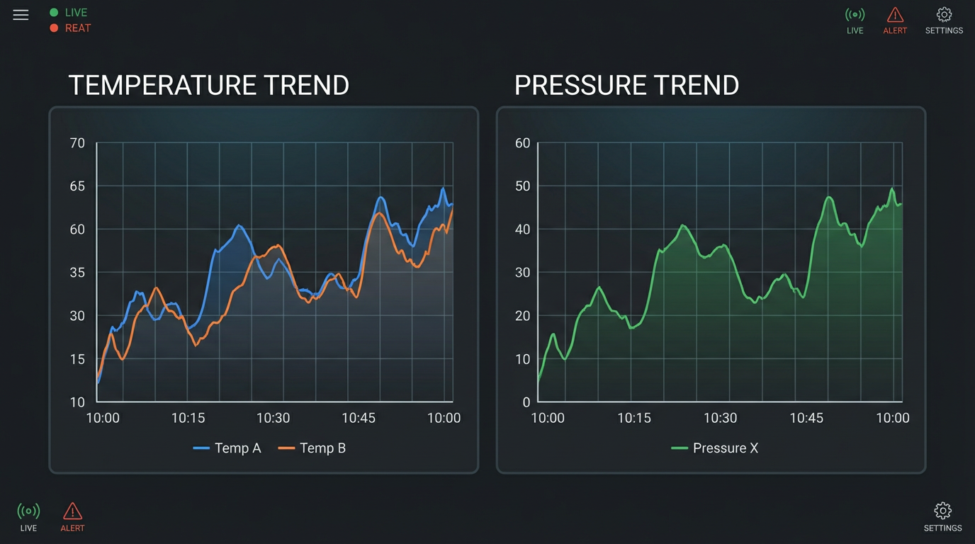
HMI and Data Logging Considerations
If you are tying a Maple Systems HMI or similar panel into the L33ER, their connection guide offers a practical trick: shape your PLC data so the HMI can log and trend it efficiently. For fixed-address PLCs, that means grouping related data into consecutive registers. For tag-based controllers like CompactLogix, it means creating arrays of INT, DINT, or REAL and putting each channel into consecutive elements.
The HMI’s data sampling object then points to the first element and treats the rest as additional channels, allowing a single data log file to carry multiple trends. If you cannot restructure PLC tags because of legacy constraints, HMIs such as EBPro allow you to use a time-based global data transfer feature that periodically copies disparate PLC tags into consecutive internal registers before logging.
This is not just an HMI convenience feature. A future engineer who needs to diagnose a sporadic fault on a 1769-L33ER system will be deeply grateful for clean, well-organized trend logs of key pressures, temperatures, speeds, and valve positions over time.
Fault Handling, Diagnostics, and Maintenance
Even a well-designed 1769-L33ER system will eventually experience module faults, network interruptions, or misconfigurations. Industrial Automation Co’s focused guide on CompactLogix 5370 module faults is an excellent practical companion to Rockwell’s manuals, and its concepts apply directly to the L33ER.
Understanding LED Status and Fault Categories
Module faults are abnormal conditions that affect controller or module operation. The CompactLogix 5370 family distinguishes between minor and major faults. Minor faults might degrade performance but allow the controller to keep running, for example a Requested Packet Interval conflict on a network device or a mismatch between configuration and actual I/O. Major faults are severe enough that the controller halts execution to prevent unsafe behavior, such as a serious communication or hardware failure.
The LED indicators on the front of the L33ER and its I/O modules are your first diagnostic tool.
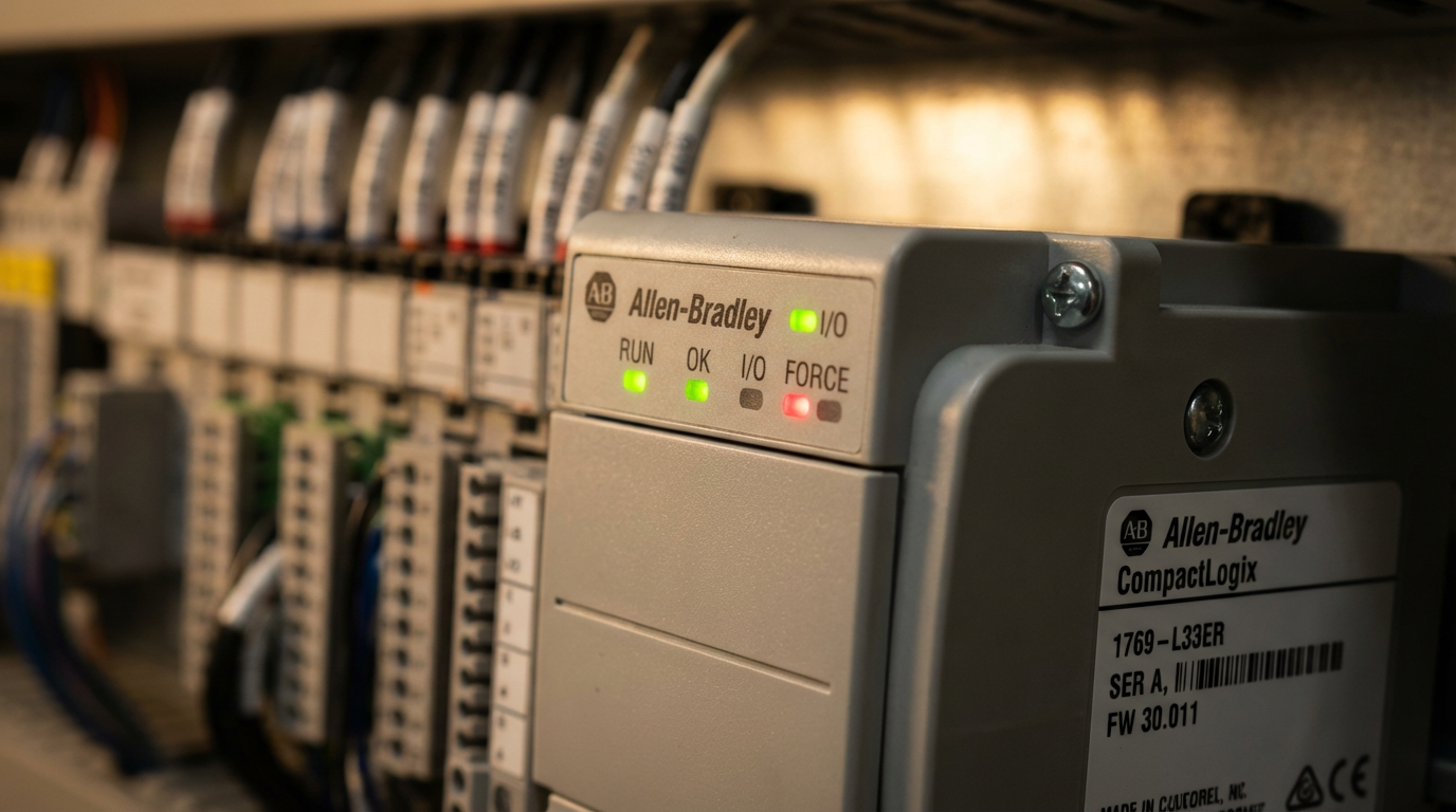
Typical meanings on these controllers include an OK LED in solid green for healthy operation, a blinking or solid red fault indicator for minor or major faults, a RUN LED indicating controller mode, port-status LEDs for serial or Ethernet activity, and module and network health LEDs on I/O cards. Unlit LEDs where you expect activity often point to power or wiring issues.
When a fault occurs, the controller generates a fault code that can be viewed in the programming software. The official CompactLogix 5370 user manuals contain detailed tables of these codes with recommended corrective actions. Rather than guessing, look up the code and follow the suggested checks.
A Structured Troubleshooting Approach
Industrial Automation Co’s article advocates a simple sequence that aligns well with field experience. First, detect and classify the fault via LEDs and software diagnostics. Second, read and interpret the fault code using Rockwell’s manual. Third, verify configuration and parameters in the project, checking for mismatched module types, incorrect slot assignments, or wrong IP settings. Fourth, physically inspect wiring, connectors, and modules for obvious damage, loose terminals, or mis-seated modules. Finally, test or swap suspected components to isolate a hardware failure.
The SolisPLC MSG tutorial adds a few network-specific tips that apply whenever communications are involved. Confirm that ladder logic is actually executing the relevant instruction by watching its enable or done bits. Use basic network tools to verify IP connectivity. Double-check that tags exist and data types on both ends match. Many “mystery” faults come down to these basics.
To prevent recurring faults, both Industrial Automation Co and AutomationDirect style guides emphasize good housekeeping: correct initial configuration, periodic inspection for wear and damage, keeping enclosures reasonably clean to avoid dust buildup, and maintaining firmware and programming software at supported levels.
Design and Integration Choices Around a 1769-L33ER
Beyond the basics of installation and programming, you will make architectural tradeoffs around the L33ER that have long-term implications for scalability and maintainability. Several of the sources in the research set touch on these indirectly, and they are worth making explicit.
MSG Versus Produced/Consumed Tags and Optimized Data Structures
When you need to move data between the L33ER and other controllers or SCADA systems, you have options. Messaging instructions, produced/consumed tags, and compact mapping UDTs each have a place.
The SolisPLC article on MSG instructions and the Ignition community discussion on PIDE data access suggest a pattern of using MSG or OPC read/write operations for configuration and occasional data, while designing compact, contiguous data structures for higher-frequency or multi-channel transfers. Producing a single structured tag per loop or per device allows drivers and HMIs to perform efficient block reads instead of many small scattered reads.
The table below summarizes the practical tradeoffs described in those discussions.
| Method | When It Fits Best | Main Advantages | Main Drawbacks |
|---|---|---|---|
| MSG instructions | Occasional data exchange between controllers or families (for example L33ER to MicroLogix). | Flexible, works across many Rockwell families; simple to set up. | Non-deterministic timing; harder to track and maintain as systems evolve. |
| Produced/consumed tags | High-priority, cyclic data between Logix-family controllers. | Deterministic updates; efficient use of network and controller. | Requires Logix controllers on both sides; more upfront design work. |
| Compact UDTs for SCADA and HMIs | Grouping PIDE and other loop data for OPC and HMI access. | Optimized reads, cleaner tag structures for clients. | Adds some PLC-side mapping logic to keep UDTs in sync with internal objects. |
Choosing wisely here will determine how well your 1769-L33ER-based system scales when you later bolt on dozens of PID loops, additional HMIs, or analytic and historian platforms.
Benefits and Limitations of the L33ER Platform
Using the L33ER brings several advantages over small fixed PLCs. It operates as part of a modular system where you can mix relay and solid-state I/O, analog modules, network adapters, and specialty cards as the machine evolves. It fits naturally into EtherNet/IP-centric architectures and benefits from the same Studio 5000 environment used for higher-end ControlLogix systems.
On the other hand, you pay for that capability through controller and software costs, and you live within the finite I/O and performance envelope of a mid-range controller. For sprawling processes with thousands of I/O points, a chassis-based controller may be more appropriate. At the low end, very simple machines can be handled by modern micro PLCs and smart relays without requiring a full CompactLogix ecosystem.
The key is to align your choice with the size, expected evolution, and integration needs of the system. Control.com’s distinction between fixed and modular PLCs is particularly useful here; the 1769-L33ER sits firmly on the modular side. If you foresee growth, extensive diagnostics, and integration into plant-wide networks, the L33ER is far easier to live with over ten or fifteen years than a slightly cheaper fixed controller chosen on price alone.
Final Thoughts from a Systems Integrator
The 1769-L33ER will do exactly what you ask of it, no more and no less. Projects that fail with this controller almost never fail because the hardware is incapable; they fail because someone skipped the planning step, ignored the installation instructions, or tried to save a few hours by rushing the I/O list and network design.
If you treat Rockwell’s official manuals as non-negotiable, apply the safety, specification, and enclosure practices laid out by AutomationDirect’s design guide, follow Control.com’s discipline on I/O and networks, and borrow proven communication and fault-handling patterns from Industrial Automation Co, SolisPLC, Maple Systems, and others, a 1769-L33ER-based system can run quietly for years. That is the difference between simply getting a machine to run and being the partner your operations team calls back for their next project.
References
- https://updc.uconn.edu/wp-content/uploads/sites/1525/2016/04/Appendix_V_Building_Automation_Standards_May2015.pdf
- https://www.isa.org/standards-and-publications/isa-standards
- https://www.fenestration.net/pdf_documents/Home%20Automation%20Systems-Install%20Guide.pdf
- https://www.plctalk.net/forums/threads/1769-l33er-best-practices-procedure-for-setting-up-a-out-the-box-plc-processor.107002/
- https://assetcloud.roccommerce.net/files/_stateelectric/4/2/2/a-b1769l33er.pdf?__hstc=4656364.2f3f33a24b44870ec4a577029c49e44b.1713398400228.1713398400229.1713398400230.1&__hssc=4656364.1.1713398400231&__hsfp=892594048
- https://support.automationdirect.com/docs/controlsystemdesign.pdf
- https://ese-co.com/knowledge/how-do-i-setup-the-compactlogix-5069
- https://www.linkedin.com/pulse/7-steps-implementing-automated-control-system-part-1-kyalo-miet
- https://www.solisplc.com/tutorials/plc-programming-msg-instruction-send-data-between-micrologix-compactlogix-plcs-studio-5000-tutorial
- https://control.com/technical-articles/the-beginners-guide-to-automation-adding-control-to-the-system/
Keep your system in play!
Top Media Coverage
Categories


Related articles Browse All
-
 amikong NewsSchneider Electric HMIGTO5310: A Powerful Touchscreen Panel for Industrial Automation2025-08-11 16:24:25Overview of the Schneider Electric HMIGTO5310 The Schneider Electric HMIGTO5310 is a high-performance Magelis GTO touchscreen panel designed for industrial automation and infrastructure applications. With a 10.4" TFT LCD display and 640 x 480 VGA resolution, this HMI delivers crisp, clear visu...
 -
 BlogImplementing Vision Systems for Industrial Robots: Enhancing Precision and Automation2025-08-12 11:26:54Industrial robots gain powerful new abilities through vision systems. These systems give robots the sense of sight, so they can understand and react to what is around them. So, robots can perform complex tasks with greater accuracy and flexibility. Automation in manufacturing reaches a new level of ...
 -
 BlogOptimizing PM Schedules Data-Driven Approaches to Preventative Maintenance2025-08-21 18:08:33Moving away from fixed maintenance schedules is a significant operational shift. Companies now use data to guide their maintenance efforts. This change leads to greater efficiency and equipment reliability. The goal is to perform the right task at the right time, based on real information, not just ...


- Q&A
- Policies How to order Part status information Shipping Method Return Policy Warranty Policy Payment Terms
- Asset Recovery
- We Buy Your Equipment. Industry Cases Amikong News Technical Resources Why choose us
- ADDRESS
-
 32D UNITS,GUOMAO BUILDING,NO 388 HUBIN SOUTH ROAD,SIMING DISTRICT,XIAMEN
Leave Your Comment