
-
Please try to be as accurate as possible with your search.
-
We can quote you on 1000s of specialist parts, even if they are not listed on our website.
-
We can't find any results for “”.
Allen-Bradley PowerFlex 525 Drive Manual: Setup and Configuration Instructions
When you have lived through enough rushed startups and midnight breakdowns, you stop treating a drive manual as a formality and start treating it as a risk-control document. The Allen‑Bradley PowerFlex 525 is a very capable variable frequency drive, but its flexibility comes with complexity. The official manuals from Rockwell Automation and the better third‑party guides are written to cover every scenario; this article translates the key setup and configuration instructions into the way a working systems integrator actually uses them on the plant floor.
The perspective here is not theoretical. These are the practices that keep HVAC systems, conveyors, and bottle‑cappers running without surprises, built on guidance from Rockwell Automation documentation such as the PowerFlex 520‑Series User Manual and Quick Start, plus proven field techniques documented by Industrial Automation Co, SolisPLC, DoSupply, and others.
How the PowerFlex 525 Manuals Are Structured
Rockwell Automation does not ship a single “PowerFlex 525 manual.” Instead, they provide a document set for the PowerFlex 520‑series (which includes the 523, 525, and 527 drives). In practice, you will handle three core documents.
The product catalog document (often referenced as 520‑PC001) focuses on ratings and selection. It explains that the PowerFlex 520‑series are low‑voltage AC drives for three‑phase motors, typically covering roughly 0.5 to 30 horsepower across several voltage classes, and it summarizes options such as communication cards and enclosure ratings.
The user manual (PowerFlex 520‑Series AC Drives User Manual, document 520‑UM001) is the real working reference. It covers safety instructions, mounting and environmental limits, power and control wiring, parameter structures, communication options, diagnostics, and maintenance practices. The third‑party engineer guides in the research notes map closely to this structure and expand it with field‑tested examples.
The quick start guide (documents such as 520‑QS001 and related quick‑start sheets) condense the essentials into a bare‑bones sequence: mount, wire, apply power, enter motor data, and run a test. These quick starts are useful, but in any non‑trivial application you will end up pairing them with the full user manual and, often, with training material such as Rockwell’s Learning+ PowerFlex 525 configuration and startup course.
On top of the official literature, there are digital editions and curated eBook platforms that host the “PowerFlex 525 Programming Manual” and similar titles. These services focus on accessibility, bookmarking, and search rather than new technical content, but they make it much easier to keep the manual open on a tablet in the panel shop or on a laptop on the plant floor instead of hunting through binders.
Safety, Preparation, and the Reality of Commissioning
Every PowerFlex 525 manual and serious guide starts with the same message: treat this as live power equipment, not a piece of software. The DC bus inside a PF525 stays charged for several minutes after you pull the disconnect, and that is enough to hurt or kill someone who assumes the bus is dead as soon as the line side is open.
Before any installation or configuration work, follow lockout/tagout procedures, verify absence of voltage with a meter, and wait roughly five minutes for the internal capacitors to discharge. The manuals emphasize, and the field experience confirms, that residual voltage can remain even after power‑off, so you do not rush this step.
Preparation is not just about safety. A clean startup begins with having the right hardware and information laid out. You need a properly sized PowerFlex 525 drive (for example, a catalog such as 25B‑D6P0N104), a compatible three‑phase motor, an input supply in the correct voltage class (commonly in the 208 to 600 volt range depending on the drive), and control devices such as pushbuttons, PLC outputs, or analog speed references. You also need a torque screwdriver, multimeter, wire stripping and termination tools, and a control panel that can provide airflow.
The manuals and engineer guides repeatedly call out the need for minimum spacing above and below the drive, around two inches of clearance, to maintain vertical airflow. That spacing becomes critical in warm or crowded cabinets. A common failure pattern in the field is a drive that technically matches the motor but is bolted into an overheated, dust‑filled panel with no airflow; the manual explicitly warns against high‑dust, high‑vibration, or high‑temperature locations without proper mitigation.
Mounting and Environmental Considerations
PowerFlex 525 drives are designed to be mounted vertically inside a control panel or enclosure with an appropriate protection rating. Rockwell literature and independent engineer guides describe using enclosures corresponding to IP20 through IP66, chosen based on how much dust, moisture, and mechanical abuse the installation will see. In practice, that means open industrial cabinets for clean MCC rooms and sealed enclosures in washdown or dusty areas.
Ambient temperature is a hard constraint. The typical guidance for PF525 units is to stay below about 122°F ambient, with proper derating if you are near the limit. The third‑party guides echo this by insisting you avoid locations above 50°C and that you never stack drives without ensuring airflow or forced cooling. When cabinet space is tight, adding a small panel fan can be the difference between a drive that trips on over‑temperature every Friday afternoon and one that just runs.
Vibration matters as well. For heavy machinery, the safer approach is to mount the drive in a rigid remote panel instead of bolting it directly onto a vibrating frame. Where that is not an option, anti‑vibration mounts and firm panel bracing are strongly recommended in the guides.
Before drilling a single hole, check the manual’s mounting diagrams and clearances, and plan the power and control wire routing so you can keep noisy conductors separated from low‑level signals. It is much easier to lay out a clean panel than to fix nuisance trips from electrical noise after the machine is already commissioned.
Power and Motor Wiring
The manuals and engineer‑oriented articles are unanimous on one point: never improvise power wiring. The PowerFlex 525 has clearly marked line and load terminals. Line power lands on L1, L2, and L3. The motor leads land on T1, T2, and T3. You must verify that the input supply voltage matches the drive’s rating; for example, the D6P0N104 variant is designed for a particular voltage range, and feeding it the wrong class of power is a fast way to destroy it.
Grounding is not optional. Both the drive chassis and the motor frame must be connected to a low‑impedance ground. The manuals and guides explicitly recommend following local and national electrical codes, using properly sized grounding conductors, and tightening terminals to the torque values specified in the documentation.
To reduce electromagnetic interference, your power wiring strategy should separate input and output conductors as much as the panel allows, and shielded motor cables should be used where practical. Multiple sources recommend grounding the cable shield at one end only, usually at the drive, to minimize ground loops while providing a path for noise.
Once the wiring is complete, do not skip the torque wrench. The PowerFlex 525 documentation and the field guides both call out terminal tightening torque as a root cause of under‑voltage faults and intermittent problems. Loose lugs on L1–L3 cause more strange behavior than most network misconfigurations ever will.
Control, I/O, and Safe Torque Off
Where many installations go sideways is in the control and safety wiring. The PF525 has a generous set of digital inputs, analog channels, and relay outputs, and it is easy to create a configuration that “sort of works” but does not match what the operator expects.
Digital inputs DI1 through DI7 are intended for run, stop, direction, and similar commands. The drive supplies a 24 volt source, and a digital common reference, so typical wiring uses this onboard supply to feed pushbuttons or PLC dry contacts back into the digital input terminals. Real‑world guides commonly use DI1 for Start, DI2 for Stop, and DI3 for Reverse, but the actual mapping is completely configurable through terminal parameters.
The PF525 supports both two‑wire and three‑wire control schemes. Two‑wire control uses a maintained contact for run; when the contact is closed the drive runs, and when opened the drive stops. This is similar to the behavior of the older 1305 drive’s “Run” inputs, and the migration literature stresses that you can reproduce 1305 behavior by matching the control scheme and torque mode. Three‑wire control uses a momentary normally open Start pushbutton and a normally closed Stop pushbutton, with a seal‑in circuit to keep the drive running after the button is released. That pattern is often preferred for operator stations and safety‑critical installations because a broken Stop circuit fails safe.
Analog inputs AI1 and AI2 support common speed reference formats, such as 0 to 10 volt signals and 4 to 20 milliamp loops. The guides detail how a remote speed potentiometer is wired using the drive’s internal 10 volt reference, the wiper input, and analog common, and how to configure whether the input expects a voltage or current signal. Relay outputs can be used for functions such as “Motor Running” status or can be assigned to parameters and driven from a PLC through mapped tags.
Safe Torque Off (STO) is perhaps the most misunderstood feature. Terminals T1 and T2 are dedicated safety inputs which, when opened, cause the drive to block IGBT gate firing and remove torque from the motor without disconnecting line power. The documentation notes that a properly implemented STO circuit can reach SIL2 or PL d safety levels when designed according to standards and Rockwell guidance. In practice, STO should be integrated with safety relays and emergency stops. Temporary jumpers across these terminals are sometimes used during commissioning under a formal risk assessment, but leaving STO permanently bypassed is a serious design flaw.
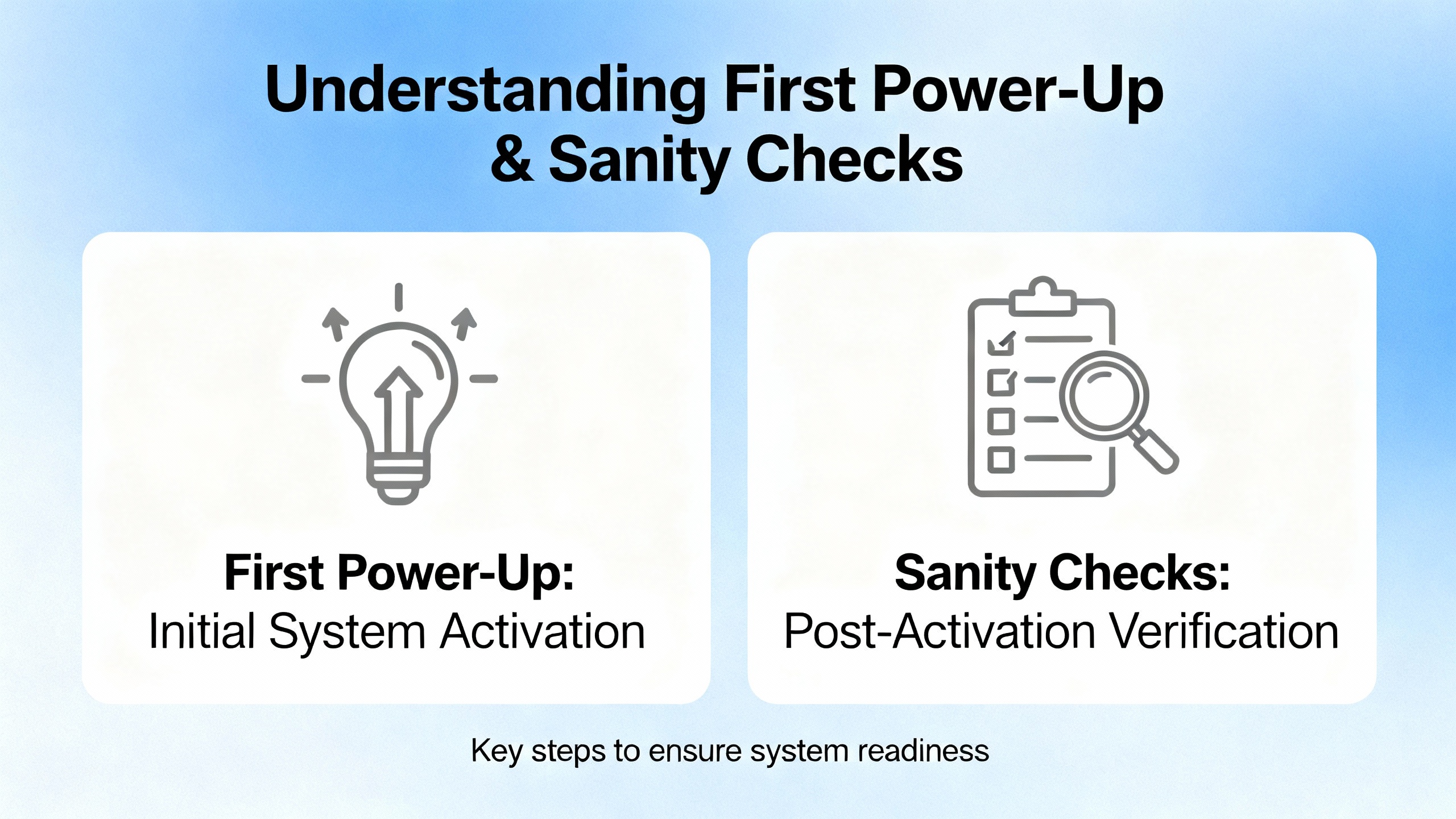
First Power‑Up and Sanity Checks
Once power and control wiring are complete, the manuals insist on a staged startup. Apply power to the input side only. If possible, leave the motor leads disconnected or mechanically secure the driven equipment so it cannot turn unexpectedly.
On first energization, the Human Interface Module (HIM) should display “rdy,” indicating that the drive is ready but not commanded to run. If the HIM immediately shows a fault, such as F004 for under‑voltage, the safe response is to de‑energize, lock out, and then re‑inspect the input power, terminal torque, and wiring against the manual’s diagrams.
The field‑oriented guides recommend not allowing the motor to rotate during this first phase. Verify that start commands are not unintentionally asserted through digital inputs, that STO is correctly wired or intentionally jumpered under control, and that any PLC logic controlling the drive is forced off during basic checks.
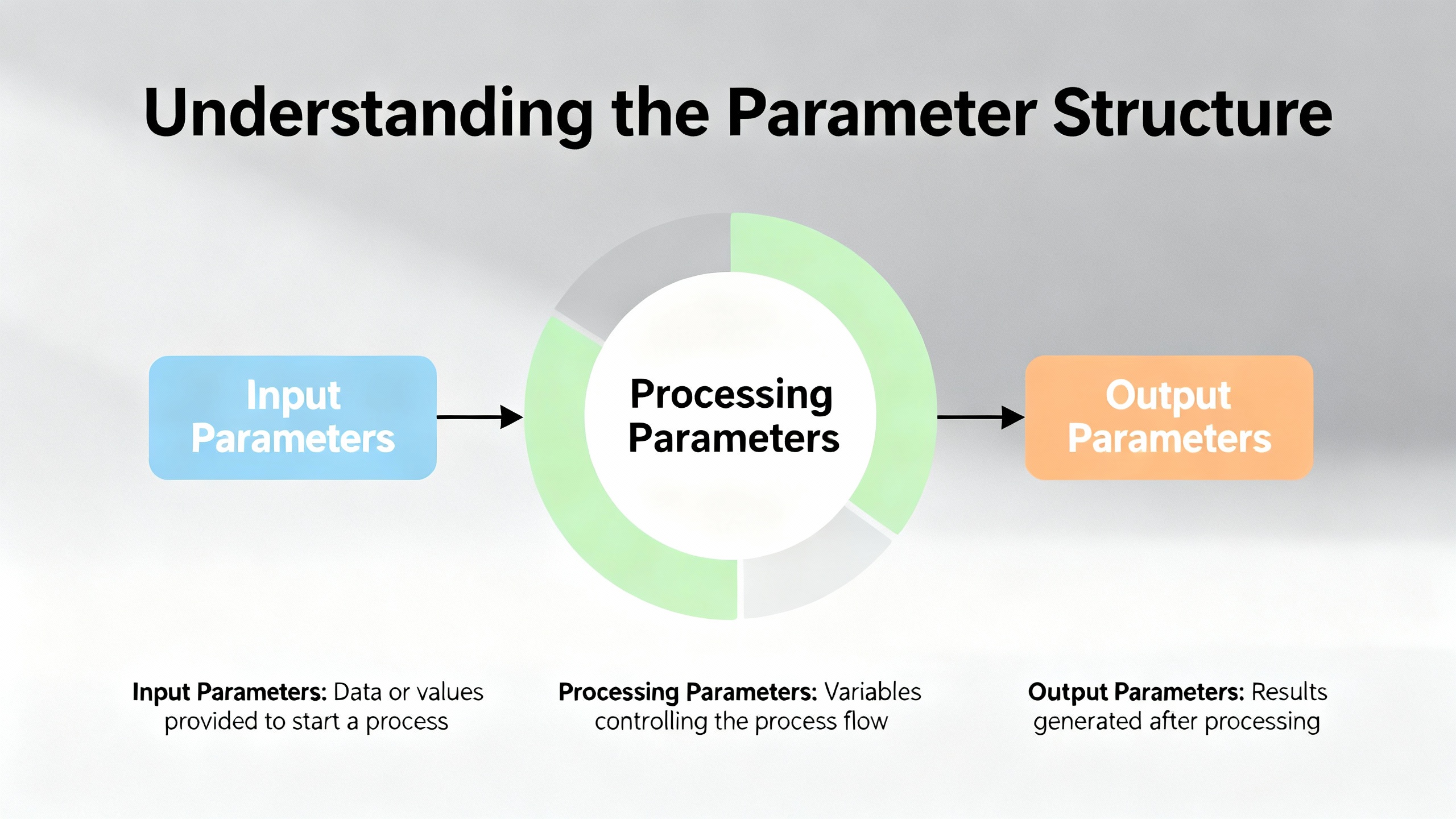
Understanding the Parameter Structure
The PowerFlex 525 derives its flexibility from a parameter system that can feel overwhelming until you see the structure. According to SolisPLC’s technical tutorial and Rockwell’s documentation, parameters are grouped into logical sections such as Basic Display, Basic Program, Terminal Blocks, Communications, Logic, and Advanced Display.
The Basic Program group covers the minimum data the drive needs to run a motor safely. Parameters P031 through P035 are used to enter motor nameplate data such as voltage, full‑load amps, and base frequency. This is non‑negotiable; if you skip accurate motor data, the drive cannot protect the motor or regulate speed properly.
Start and speed source selection are controlled by P036 and P038. P036 chooses where the run command comes from. The manuals and guides describe options such as digital inputs, the HIM keypad, or a communication port. P038 selects the speed reference, which could be an analog input, the HIM pot, or a network command such as EtherNet/IP.
Acceleration and deceleration profiles are managed by P039 and P040. These parameters define how quickly the drive ramps the motor speed up and down. Frequency limits are set by P043 and P044, which establish the minimum and maximum output frequency and effectively cap how slow or fast the motor can run under normal commands.
A compact way to visualize the essentials is to think in terms of a small core set of parameters.
| Parameter(s) | Role in setup | Practical note from field use |
|---|---|---|
| P031–P035 | Motor nameplate data | Enter exactly what is on the motor nameplate before any test runs. |
| P036 | Start command source | Decide early whether run comes from terminals, keypad, or network. |
| P038 | Speed reference source | Match this to your wiring or PLC commands to avoid confusing behavior. |
| P039, P040 | Acceleration and deceleration times | Tune these to match the mechanics; defaults are often too aggressive. |
| P043, P044 | Minimum and maximum frequency limits | Use these to enforce safe speed ranges for the driven equipment. |
| P053 | Communication module reset | Setting this to the documented reset value reboots comms after IP changes. |
The manuals also describe more advanced torque modes such as sensorless vector or flux vector control. Migration guidance for replacing older Volts‑per‑Hertz drives, like the Allen‑Bradley 1305, recommends leaving the PF525 in basic V/Hz mode when you are trying to match legacy behavior. Those same migration notes suggest setting the motor overload current parameter slightly above the motor full‑load amps when the motor has a service factor above one, instead of enabling more complex modes that require auto‑tuning, unless you truly need the tighter torque response.
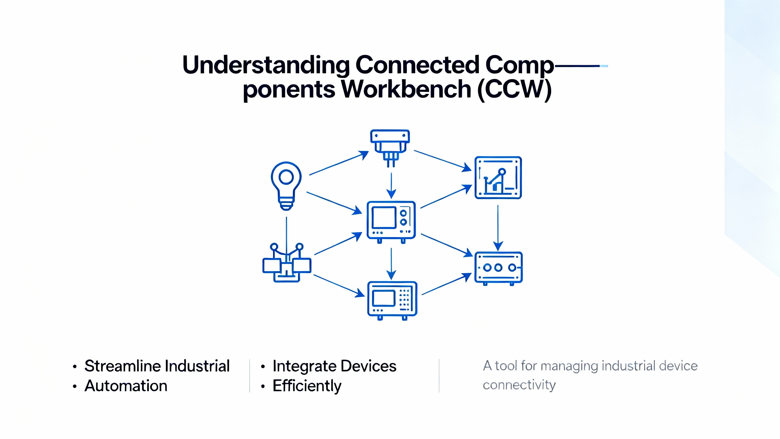
Using Connected Components Workbench (CCW)
While the keypad is fine for quick adjustments, serious projects benefit from using Rockwell’s Connected Components Workbench (CCW) software. The engineer‑focused guides describe CCW as the preferred tool for:
Configuring the drive through startup wizards that walk you through motor data, control sources, and ramp times, mirroring the structure of the manual but in a friendlier interface.
Backing up and restoring parameter sets to and from a PC, which is invaluable for documenting the final configuration and cloning drives.
Monitoring live values and diagnostics, which simplifies commissioning and troubleshooting compared to scrolling through codes on the keypad.
Performing firmware updates with proper version control, so that the drive’s firmware matches what your PLC project expects.
A pragmatic workflow that aligns with both the manual and decades of field practice is to perform basic wiring checks, then connect with CCW over USB or Ethernet and walk through the startup wizard before you ever energize the motor. That process ensures parameters such as P031–P035, P036, P038, P039, and P040 are set coherently, rather than being tweaked piecemeal in response to odd behavior.
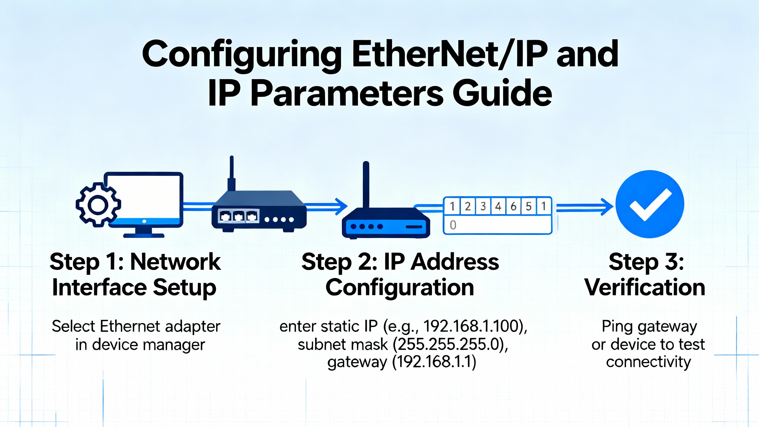
Configuring EtherNet/IP and IP Parameters
The PowerFlex 525 includes an embedded EtherNet/IP port on Ethernet‑enabled catalog numbers. To integrate the drive into a control network, you must configure its IP settings. Rockwell documentation and multiple independent tutorials converge on a simple pattern.
IP behavior is driven primarily by a parameter that selects whether the drive uses values from its internal parameter set or obtains an address through a service such as BOOTP or DHCP. In many guides this is parameter C128. Setting this selector to the documented “Parameters” value instructs the drive to use IP information stored in subsequent parameters instead of asking for an address from a server.
The IP address itself is defined by four parameters such as C129 through C132, each representing one octet of the IPv4 address. The subnet mask is similarly entered into four parameters like C133 through C136. Some guides also mention gateway address parameters in the C137 to C140 range when the drive must communicate across subnets.
A small table captures the relationship.
| Parameter range | Meaning | Example usage |
|---|---|---|
| C128 | IP address selection mode | Set to “Parameters” to use static IP values. |
| C129–C132 | IP address octets | Values such as 192, 168, 1, 71 for an address of 192.168.1.71. |
| C133–C136 | Subnet mask octets | Values such as 255, 255, 255, 0 for a common mask. |
| C137–C140 | Gateway address octets | Used when traffic must cross a router. |
After entering IP, subnet, and any gateway values, the drive’s communication module must be reset for the changes to take effect. The documentation describes using either a power cycle or a communication reset parameter, such as setting P053 to the communication module reset value. Independent guides call this out explicitly and note that if you skip the reset, the drive will keep using the old IP.
On the PC side, commissioning usually involves assigning the engineering laptop an address in the same subnet, connecting an Ethernet cable, and verifying communication with tools such as ping and Rockwell’s RSLinx or Studio 5000. The sources emphasize assigning unique IP addresses, coordinating with plant IT, and documenting the final settings on labels and project records to avoid future conflicts or lost devices.
Static addressing is strongly recommended for control devices like drives. While BOOTP or DHCP can help during early commissioning, DoSupply and SolisPLC tutorials both highlight the stability benefits of fixed addresses, especially when PLC programs use module‑defined tags linked to specific IPs.
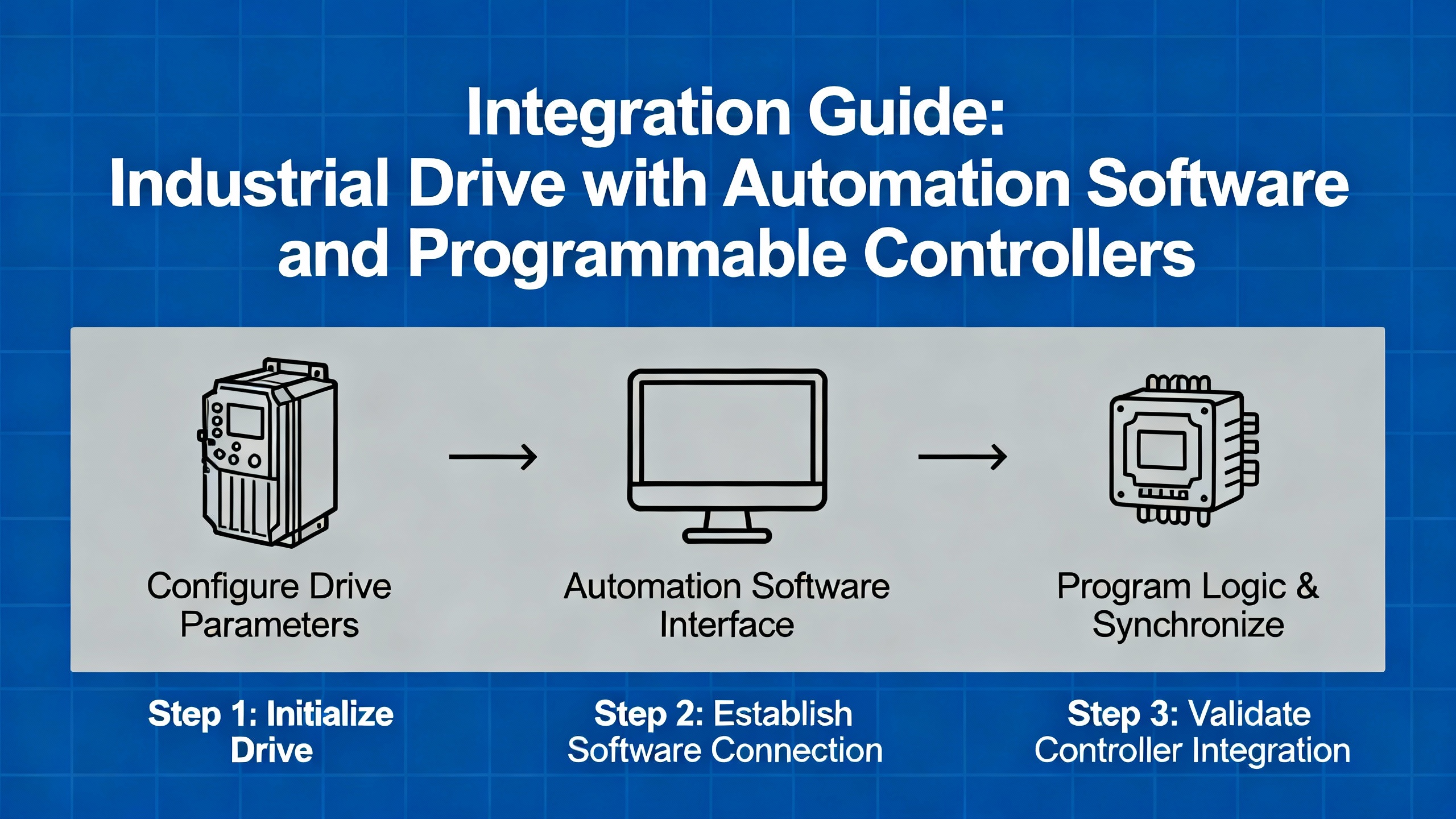
Integrating the PF525 with Studio 5000 and Logix Controllers
Once the drive is on the network, the next step is integration with a CompactLogix or ControlLogix controller using Studio 5000. Rockwell calls this “Premier Integration,” and the third‑party tutorials walk through it in detail.
The process begins by adding the PowerFlex 525 as an EtherNet module in the controller’s I/O tree, using the correct profile and matching the drive’s actual firmware revision. If the firmware version in the Studio 5000 project does not match the drive, you can run into tag mismatches or configuration warnings.
When you add the module, Studio 5000 automatically generates a tag structure. Input tags (often under a prefix such as PF1:I) represent status coming from the drive: running state, fault bits, digital input status, and so on. Output tags (under PF1:O) represent commands going to the drive: start, stop, forward, reverse, speed reference, and fault reset. Tutorials stress that outputs in the PLC are inputs to the drive, and inputs in the PLC are outputs from the drive, which is an easy mental inversion to get wrong.
A simple but robust pattern is to wire your physical Start and Stop pushbuttons into the PLC’s discrete inputs, handle the seal‑in and safety logic in ladder, and then drive the PF525’s command tags from that logic. Basic ladder rungs assert the start command tag when the sealed‑in run condition is true, drop it when Stop or a safety input is active, and write a frequency command tag based on an operator speed setting or a PLC recipe.
More advanced examples in the SolisPLC tutorials show mapping the drive’s onboard digital inputs and relay outputs into the PLC via the module configuration, so that a pushbutton wired to a drive terminal appears as a bit in an input word such as DigInStatus, and a relay contact driven from the PLC appears as a value in an output word such as RelayOut2Level. The manuals state that relay outputs are controlled by parameter selections like t081 and t082, and the tutorials recommend using move instructions to write whole values rather than toggling single bits when controlling those parameters from a PLC.
Throughout this integration, the guidance from both Rockwell and independent engineers is to keep sources of control unambiguous. If P036 is set to use terminal inputs as the start source while the PLC is trying to control the drive over EtherNet/IP, the result is confusing behavior at best and unsafe operation at worst.
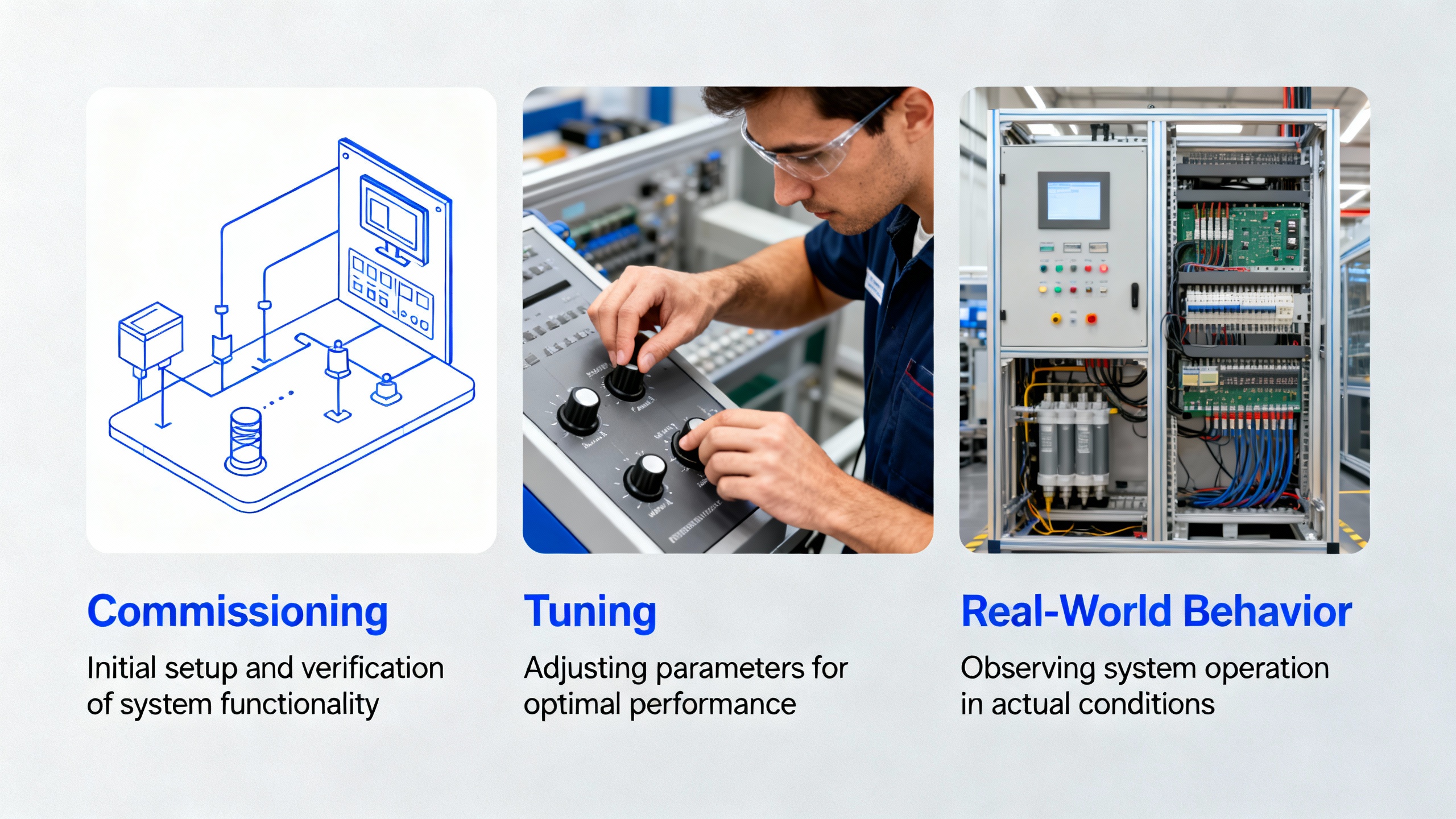
Commissioning, Tuning, and Real‑World Behavior
After wiring, parameterization, and integration, the real test is how the machine behaves under load. The manuals and engineer guides all recommend a supervised, incremental approach.
With the motor coupled, issue a Start command from the chosen source and watch the acceleration, direction, and current. If the motor turns in the wrong direction, the correct fix is to swap any two of the motor leads at the drive output terminals T1, T2, and T3, rather than changing logic or reversing motor phasing elsewhere. Verify that any STO or safety circuits behave as intended when an emergency stop is triggered.
Acceleration and deceleration times are more than comfort settings; they directly affect product quality and mechanical stress. A real bottling line example from the Industrial Automation Co guide describes a bottle‑capping conveyor that surged and caused jams with default ramp times. Increasing parameters P039 and P040 to around five seconds smoothed the motion and eliminated the jams. That case is typical: default ramps exist to prove the drive works, not to match your process.
Frequency limits set in P043 and P044 also deserve deliberate attention. If an operator can command the drive beyond the mechanical or safety limits of the driven machine, that is a design choice, not an accident, and it should be documented and risk‑assessed. For many pumps, fans, and conveyors, setting a conservative maximum frequency in P044 and a reasonable minimum in P043 prevents both overspeed and stall conditions from careless commands.
Diagnostics in the manual and third‑party tutorials list common faults such as over‑current, over‑voltage, under‑voltage, over‑temperature, and ground fault. The recommended practice is to treat each fault as a clue: verify wiring, mechanical load, and parameter settings against the manual’s fault tables, and avoid the temptation to simply add more time delays or fault resets in PLC logic to mask the underlying issue.
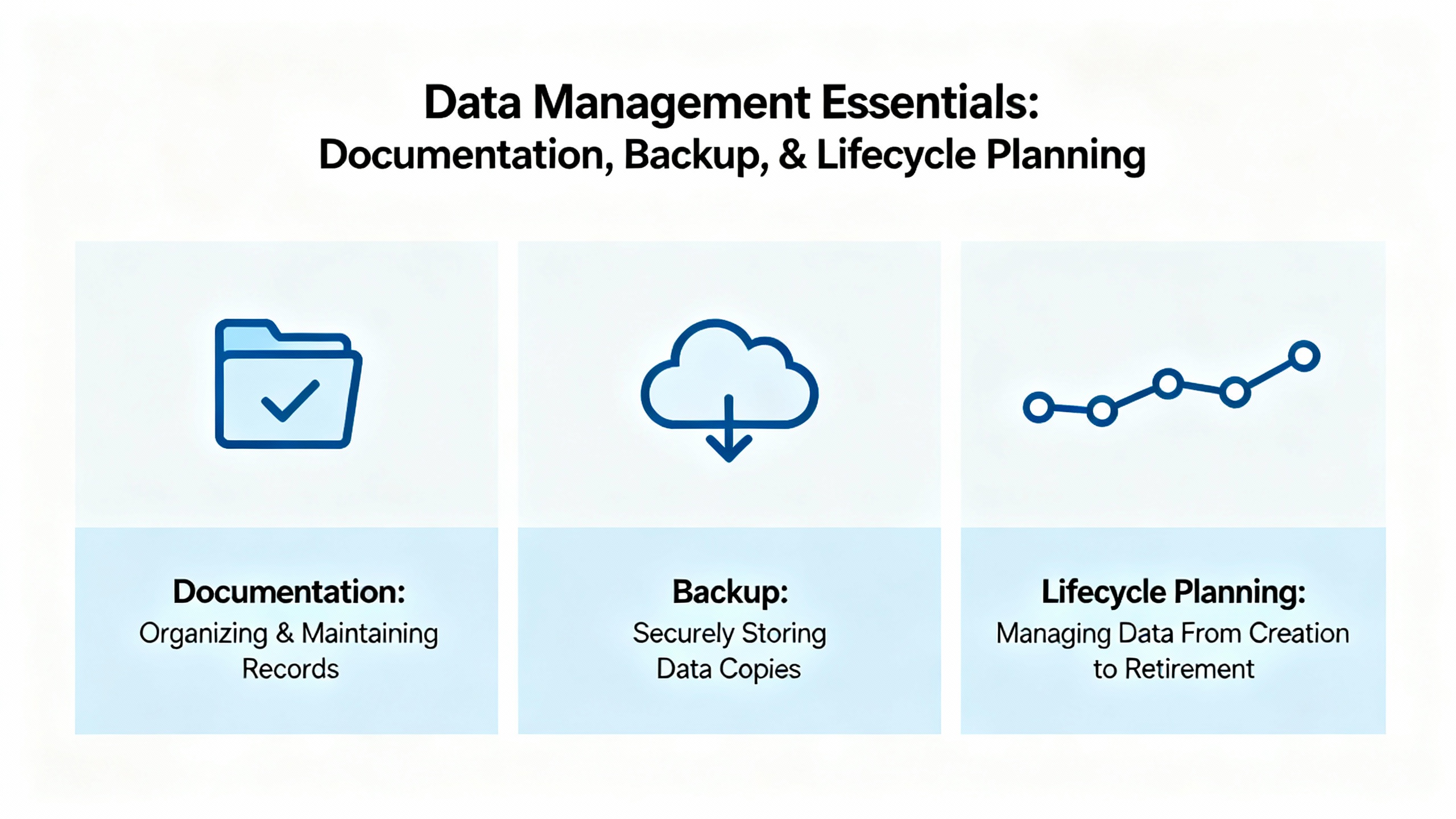
Documentation, Backup, and Lifecycle Planning
One difference between a “finished” job and a robust system that someone will thank you for is documentation. Rockwell’s manuals and the better engineer guides converge on a simple discipline.
Back up the final parameter set to removable media. The PF525 HIM can store parameters to a USB device on some versions, and CCW can save them to a PC project file. That backup becomes your template when you replace a drive or need to clone settings.
Label everything. That includes power and control terminals on the drive, motor leads, Ethernet ports, and external safety circuits. Record the drive catalog number, serial number, firmware version, and a list of critical parameters in a configuration sheet that lives inside the control cabinet.
For modernization projects where you are replacing legacy drives such as the 1305, migration guides strongly recommend uploading and saving the old drive’s parameters before it fails. They advise comparing each non‑default parameter against defaults and deliberately mapping required settings onto the PF525 rather than assuming that “factory defaults” are equivalent between generations.
Maintenance recommendations in the user manual emphasize keeping heat sinks and vents clear, periodically checking fans and terminations, monitoring operating temperature and load over time, and using diagnostics to detect degrading conditions before they become failures. In practice, that means making the drive’s diagnostic data visible, whether through a local HMI, SCADA system, or routine inspections with CCW.
Working with Digital Manuals and Training Resources
Several of the referenced sources describe the PowerFlex 525 manuals as digital documents within curated libraries or training platforms. While those descriptions do not add new technical content, they highlight a practical point: having the manual searchable and bookmarkable on a laptop, tablet, or phone changes how effectively you can use it.
Digital library platforms emphasize quick loading, clean interfaces, and the ability to bookmark sections you revisit often, such as wiring diagrams, parameter tables, and fault code lists. They also stress secure access and consistent formatting across devices. Rockwell’s own Learning+ course offerings complement this by providing structured training on configuration and startup, assuming that learners already understand basic electrical safety.
In the field, the combination of a digital manual, a recorded parameter backup, and a simple internal “startup checklist” goes a long way toward making the PF525 feel predictable instead of mysterious.

Common Pitfalls and How to Avoid Them
The recurring problems across sites tend to look similar. Skipped safety steps, such as ignoring lockout/tagout or the five‑minute discharge wait, produce the obvious hazards. More subtle issues include drives installed in overheated or dusty cabinets with inadequate clearance, STO circuits that are bypassed rather than designed in, and control schemes that mix keypad, hardwired, and network commands in confusing ways.
On the networking side, devices left in BOOTP or DHCP mode can lose their IP addresses after power outages or network changes, breaking controller communication until someone remembers how the drive was originally discovered. Using the selector parameter to lock in static IP addressing, and documenting the chosen address, prevents that whole failure mode.
Another frequent issue is treating parameter edits as trial‑and‑error. The manuals and field guides recommend using tools like CCW’s “show non‑default parameters” feature so that you can see what has actually been changed from factory defaults. Every non‑default parameter should have a reason and a note in your configuration record.
Finally, do not underestimate the value of tuning accel and decel ramps and frequency limits to the actual mechanics. As the bottle‑capping case demonstrates, many “mechanical” problems are simply the result of a drive that is defaulted instead of tuned.
Brief FAQ
What is the practical difference between the PowerFlex 525 quick start guide and the full user manual? The quick start guide gives you just enough information to mount, wire, enter basic motor data, and run a simple test. The full user manual adds detailed safety guidance, communication setup, diagnostics, advanced parameter descriptions, and selection and derating information. For anything beyond a trivial standalone fan, you should treat the quick start as a checklist and the user manual as the authoritative reference.
When should I use the keypad versus CCW or Studio 5000 for configuration? Use the keypad when you need to make a small change in the field, such as adjusting a ramp time or confirming a start source. Use CCW when you are commissioning a drive, need a complete backup, or are comparing configurations. Use Studio 5000 parameter access when the drive is tightly integrated with a Logix controller and you want to keep configuration under version control with the PLC project.
Should I run the PowerFlex 525 in V/Hz or sensorless vector mode? Migration guidance for replacing older V/Hz drives recommends keeping the PF525 in V/Hz torque mode when you are trying to match existing behavior and do not need tight torque control. Sensorless vector and more advanced modes can provide better low‑speed performance but require additional setup, such as auto‑tuning, and add complexity. The right choice depends on whether your process demands that extra performance.
Is it worth assigning static IP addresses to drives? Yes. Rockwell documentation and multiple engineer guides recommend static IPs for drives so that PLC configurations and SCADA references stay valid over time. Static addressing, combined with proper documentation and network segmentation, reduces troubleshooting effort and lowers the risk of unexpected communication failures after network changes.
A PowerFlex 525 is only as reliable as the engineering discipline behind it. If you treat the manuals and trusted guides as design tools, wire and configure the drive with the same care you would put into a safety relay, and document what you did, the PF525 will quietly run in the background of your plant for years—and you will be the person people call when they want their next project done right.
References
- https://production.cbts.edu/Textbook/840XnO/897528/Powerflex-525-Programming-Manual.pdf
- https://admisiones.unicah.edu/Resources/P9zoyX/7OK132/AbPowerflex525Manual.pdf
- https://www.plctalk.net/forums/threads/powerflex-525-configuration-with-logix-designer.122029/
- https://resources.onemotion.tech/setup-troubleshooting-powerflex.html
- https://www.asteamtechno.com/how-to-set-up-and-program-your-allen-bradley-powerflex-525-vfd-a-complete-guide/?srsltid=AfmBOoqTxGL9QMwl00zB7v7fdYgWbHI1Dd75W_WQXA9kl4klTfWVhqKh
- https://www.precision-elec.com/allen-bradley-power-flex-525/?srsltid=AfmBOorIYZBOER7iMoyJiVvMYCg4fZYFdSEkGDkLWFDEcc1k3RKGM7fF
- https://www.solisplc.com/tutorials/powerflex-525
- https://industrialautomationco.com/blogs/news/how-to-set-up-and-program-your-allen-bradley-powerflex-525-vfd-a-complete-engineer-s-guide-4?srsltid=AfmBOop0yRIqlxCRuj7829Sm1zFIrktfUbLId8WxQArJxgUO-fcM5rWB
- https://pages.rexelusa.com/blog/automation/drive-modernization-part-iii-1305-to-powerflex-525
- https://www.dosupply.com/tech/2021/01/29/tutorial-how-to-set-up-ip-address-parameters-for-the-powerflex-525/?srsltid=AfmBOoojiseccWCeS6TRGnFh_ZBFf8Pne-UnXVoGJdDRzeN4JwbVKz7p
Keep your system in play!
Top Media Coverage
Categories


Related Products
-
 Power Supply ModuleManufacturer: Honeywell
 -
Power Supply ModuleManufacturer: Honeywell
-
POWER SUPPLY MODULEManufacturer: Honeywell
-
Expansion I/O base optionsManufacturer: Honeywell
-
Power Supply ModuleManufacturer: Honeywell
-
POWER SUPPLY MODULEManufacturer: Honeywell
-
I/O Interface ModuleManufacturer: Honeywell
-
ExpansionI/O BaseManufacturer: Honeywell
-
Main CPU base optionsManufacturer: Honeywell
-
Expansion I/O base optionsManufacturer: Honeywell

Related articles Browse All
-
 amikong NewsSchneider Electric HMIGTO5310: A Powerful Touchscreen Panel for Industrial Automation2025-08-11 16:24:25Overview of the Schneider Electric HMIGTO5310 The Schneider Electric HMIGTO5310 is a high-performance Magelis GTO touchscreen panel designed for industrial automation and infrastructure applications. With a 10.4" TFT LCD display and 640 x 480 VGA resolution, this HMI delivers crisp, clear visu...
 -
 BlogImplementing Vision Systems for Industrial Robots: Enhancing Precision and Automation2025-08-12 11:26:54Industrial robots gain powerful new abilities through vision systems. These systems give robots the sense of sight, so they can understand and react to what is around them. So, robots can perform complex tasks with greater accuracy and flexibility. Automation in manufacturing reaches a new level of ...
 -
 BlogOptimizing PM Schedules Data-Driven Approaches to Preventative Maintenance2025-08-21 18:08:33Moving away from fixed maintenance schedules is a significant operational shift. Companies now use data to guide their maintenance efforts. This change leads to greater efficiency and equipment reliability. The goal is to perform the right task at the right time, based on real information, not just ...


- Q&A
- Policies How to order Part status information Shipping Method Return Policy Warranty Policy Payment Terms
- Asset Recovery
- We Buy Your Equipment. Industry Cases Amikong News Technical Resources Why choose us
- ADDRESS
-
 32D UNITS,GUOMAO BUILDING,NO 388 HUBIN SOUTH ROAD,SIMING DISTRICT,XIAMEN
Leave Your Comment