
-
Please try to be as accurate as possible with your search.
-
We can quote you on 1000s of specialist parts, even if they are not listed on our website.
-
We can't find any results for “”.
How to Select a Motion Controller for Multi‑Axis Coordination Systems
When a project involves more than one axis, the motion controller stops being a commodity box and becomes the heart surgeon of the machine. You can have high‑torque motors, precision bearings, harmonic gearboxes, and 24‑bit encoders; if the controller and architecture are wrong, the machine will never coordinate the way you expect.
I have seen multi‑axis projects succeed or fail almost entirely on controller selection and system architecture. The good news is that the right decision is repeatable if you approach it systematically, not as a last‑minute part number choice.
This article walks through how to select a motion controller for multi‑axis coordination systems, based on field experience and supported by guidance from sources such as Automate, Motion Control Tips, Tech Briefs, Anaheim Automation, AutomationDirect, and Control Engineering.
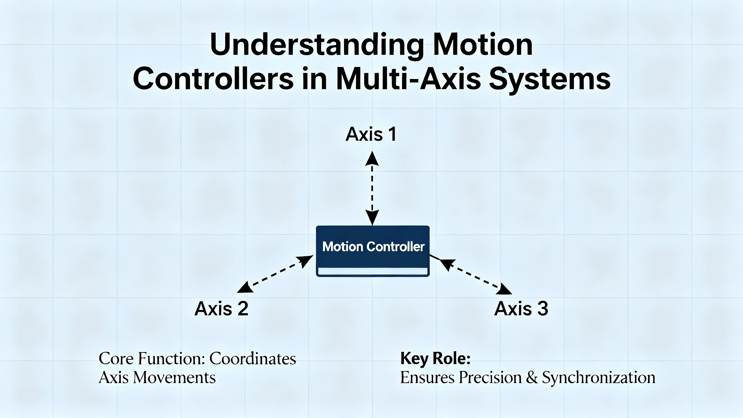
What a Motion Controller Really Does in a Multi‑Axis System
A modern motion control system is more than a drive bolted to a motor. As summarized in Motion Control Tips and in fundamentals overviews from Mide and others, the core building blocks look like this:
A motion controller acts as the system brain. It defines the motion path, executes sequences, closes servo loops in many architectures, and sends low‑power command signals.
A motor drive or amplifier receives those commands and turns them into voltage and current for the motor, directly controlling torque, speed, and direction.
The motor converts electrical power into mechanical motion.
Feedback devices such as encoders or resolvers measure position and speed and report back so the controller can correct error in real time.
In multi‑axis systems, the controller also has to coordinate axes: generate interpolated trajectories, manage electronic gearing or camming, and maintain timing relationships with the rest of the machine.
Motion Control Tips describes a typical control hierarchy from the top level down through the loops:
| Level in hierarchy | Typical function | Where it often runs |
|---|---|---|
| Executive / sequencing | Recipes, states, safety, interlocks | PLC, PAC, or PC |
| Motion equation generation | Path planning, profiles, cams | Motion controller or PAC |
| Interpolation | Multi‑axis position commands over time | Motion controller or high‑end PLC |
| Position loop closure | Position error control | Controller or smart drive |
| Velocity loop closure | Speed regulation | Drive or smart drive |
| Current / torque loop and commutation | Motor phase currents, torque, field orientation | Drive or smart drive |
| Power modulation | IGBT or MOSFET switching to motor | Drive |
The lower you go in that table, the more bandwidth you need and the less latency you can tolerate. That is why, as Motion Control Tips notes, you do not want to close fast current loops across a high‑latency network. Push too much high‑frequency feedback over Ethernet and the loops can become unstable.
For multi‑axis coordination, you usually want the interpolation and at least the position loops under one tightly synchronized roof, whether that is a dedicated motion controller, a PAC, or an integrated PLC with strong motion features.
Start with the Motion, Not the Hardware
Before you look at controller datasheets, you should be looking at the machine. Automate highlights a simple mnemonic from a Rockwell Automation engineer: mass, move, and means.
The mass is what you are moving: payloads, tooling, carriages, conveyors, web material, robot arms.
The move is how you need them to move: distances, speeds, accelerations, and required profiles; whether you need straight‑line moves, corner blending, complex cams, or free‑form kinematics.
The means are what you are using to move them: linear actuators, belt axes, rotary stages, gearboxes, and the motor technologies and drives already chosen or under consideration.
That combination sets the coordination problem. A single slow actuator indexing once every few seconds is one story. Eight axes of high‑speed packaging, a gantry synchronized to a conveyor, or a robot handing parts to another robot is another story entirely.
When I define multi‑axis requirements with a customer, I always nail down a few points in writing:
How many axes now, and how many likely in the next generation of the machine.
Which axes must be coordinated to follow the same path in space, not just arrive at endpoints at roughly the same time.
What cycle times and latency budgets exist. A machine running 300 parts per minute has a cycle of about 200 ms, as Automate points out in an example. Inside that window, every operation and idle period must fit, including vision, safety checks, and motion corrections.
What profile complexity is needed: simple point‑to‑point moves, electronically geared axes, electronic cams, or full kinematics and G‑code.
You cannot sensibly choose a controller or architecture until those answers are on the table.
Choosing the Overall Control Architecture
With requirements in hand, the next question is not “which controller model,” but “which overall architecture.” Automate and Tech Briefs both emphasize that modern projects typically fall into a small set of patterns, each with strengths and trade‑offs for multi‑axis coordination.
Smart Drives with Distributed Motion
Smart drives with onboard processors can close local loops and even handle simple single‑axis moves. Daisy‑chained in a distributed architecture, they can coordinate basic multi‑axis behavior by passing commands between drives. Automate uses an XZ gantry as an example: a Z‑axis drive starts its move, then triggers the X‑axis drive, so the combined motion goes from one point to another.
The upside is reduced cabinet complexity and wiring. Instead of home‑running every motor to a central rack, you may simply daisy‑chain the drives. That lowers cabling cost and removes a number of physical failure points.
The limitation is coordination quality. The same Rockwell engineer quoted by Automate notes that this architecture does not give you truly synchronized vector moves or corner rounding. Each drive moves itself and arrives when it arrives. For machines that need precise coordinated paths or contouring, you eventually hit a wall.
PLCs with Motion Functions
PLCs remain the workhorse of industrial automation. They handle large I/O counts, timing, counting, and sequencing with predictable behavior. Because they are essentially rugged computers, they can talk directly to drives and control motion.
For a handful of non‑synchronized axes, a PLC with basic motion function blocks can be a very economical and compact answer. Low‑end PLCs are well suited to start, stop, and simple jog profiles.
As Automate and Control Engineering both point out, there are trade‑offs. Traditional ladder logic is not an ideal language for describing motion. Low‑end PLCs may have slower communication with drives and reduced ability to handle large, fast coordinated moves. Engineers also shoulder the burden of configuring not only the drive, but the interface and the network between PLC and drive.
High‑end PLCs close some of that gap. With modern processors and standardized motion function blocks derived from PLCopen and IEC 61131‑3, they can perform linear interpolation and certain types of coordinated motion that once required a stand‑alone motion controller. For many mid‑range multi‑axis systems, an advanced PLC or PAC with integrated motion is now a practical option.
Programmable Automation Controllers (PACs)
PACs bring logic, motion, robotics, safety, and often HMI into a single hardware and software platform. As described in Automate and Control Engineering, these systems use high‑performance processors and significant memory so one environment can configure drives, robots, safety functions, and machine sequencers without juggling multiple vendors’ tools.
For multi‑axis coordination, this can be very attractive. Interlocks, state machines, motion profiles, and safety interactions are all engineered in one project file. PACs are used in applications ranging from three‑axis instruments up to full CNC machines, depending on cost and footprint constraints.
Vendors aim to make as much setup as possible configurable, not hand‑coded. General configuration often happens via dialog boxes and templates, while application‑specific functions remain open for programming so you can protect your intellectual property.
PLC plus Standalone Motion Controller
For extremely demanding multi‑axis systems, Automate notes that the classic combination of a PLC with a dedicated motion controller is still hard to beat. These controllers use purpose‑designed hardware and firmware to support sub‑millisecond loop times, sub‑micron precision, G‑code for CNC, and sophisticated kinematics.
If you are coordinating multiple robots, or combining many fixed axes into a virtual kinematic system, a high‑end motion controller is often the pragmatic choice. It can accept complex commands, decompose them into trajectories for each axis, and manage hundreds of coordinated axes while the PLC focuses on machine‑level logic.
The trade‑offs are increased hardware count, more complex programming, and higher upfront cost. In my own work, I reserve this architecture for machines where precision, dynamic performance, or kinematic flexibility clearly justify that complexity.
PC‑Based Soft Motion
Automate also describes PC‑based “soft motion,” in which high‑performance industrial PCs run motion algorithms under a real‑time OS. Hardware is commodity; functionality is primarily in software. That allows you to benefit from the rapid upgrade cycles of PC processors.
The advantage is flexibility and raw computing power. For custom algorithms, advanced analytics, or when you want motion tightly tied to PC‑side applications, soft motion is attractive.
The risk is lifecycle. PLC and drive vendors routinely support products for decades. An industrial PC you buy today may be unavailable a few years from now. Control Engineering stresses that lifecycle support, not just feature lists, should be part of controller selection, and soft motion requires deliberate planning for hardware refresh.
Architecture Comparison at a Glance
A concise way to think about these options for multi‑axis coordination is:
| Architecture | Multi‑axis coordination strengths | Typical limitations for coordination |
|---|---|---|
| Smart drives, distributed | Simple multi‑axis, reduced wiring, low cost | Limited interpolation, weak vector moves and blending |
| PLC with basic motion | Good for a few unsynchronized axes | Limited multi‑axis features and real‑time bandwidth |
| High‑end PLC / PAC with motion | Integrated logic and motion, strong interpolation options | May still struggle with extreme axis counts or kinematics |
| PLC plus dedicated motion controller | Best for high‑axis‑count, high‑precision, complex kinematics | Higher hardware and engineering cost |
| PC‑based soft motion | Very flexible algorithms, strong compute | Shorter hardware lifecycle, more IT complexity |
Once you understand where your project sits on that spectrum, you can start matching product families to the task.
Performance and Cycle‑Time Requirements
Performance is where multi‑axis coordination stops being abstract. Automate gives a concrete illustration: a machine processing 300 parts per minute has about 200 ms per part. Every operation—motion, sensing, alignment, and idle time—must fit within that 200 ms.
If vision feedback is involved, the window tightens further. In one example, the time from image acquisition to the end of the correction window is 30 ms. The camera needs roughly 5 ms to capture an image, 5 ms to process it, and 5 ms to transmit the data, leaving the controller the remaining fraction of that 30 ms to compute and apply a corrective move. Hull from Yaskawa emphasizes that, while you may not know these numbers exactly at project kickoff, you must establish a reasonable performance margin.
This directly impacts controller choice:
If your cycle time is generous and coordination is loose, a modest PLC or PAC with motion can be sufficient.
If you are doing extremely fast coordinated motion, as Automate points out, you may need a controller with a larger CPU purely for speed, even if its axis and memory capacity are more than you strictly need.
Tech Briefs describes Ethernet‑based factory networks with update times ranging from around 500 ms down to about 250 microseconds, depending on protocol. Modbus TCP is described with typical two‑device update times in the 20 to 500 ms range. EtherNet/IP in common applications falls roughly between 10 and 100 ms. UDP links can operate around 1 to 4 ms. EtherCAT with CANopen over EtherCAT can reach cyclic update times on the order of 0.25 ms for process data.
Those figures determine what loops you can afford to close across the network and what must stay local to drives. If your interpolated path requires position updates every millisecond, you will not deliver that reliably over a non‑deterministic 50 ms channel.
In my own projects, I always document three things early: the fastest move or cam segment, the smallest time window for any feedback‑driven correction, and the worst‑case network and controller latencies. The controller and network must clear that bar comfortably, not just on paper, but with real traffic from HMIs, historians, and diagnostics.
Axis Count, Coordination Modes, and Features
Axis count alone does not define controller choice, but it narrows the field. There is a difference between eight axes that occasionally move at the same time and eight that must follow a precisely coordinated cam, or between three axes of a DNA sequencer and three axes on a high‑speed palletizer.
Automate notes that high‑end PLCs and PACs now perform functions that used to be strictly in the realm of stand‑alone motion controllers, such as linear interpolation and some forms of coordinated motion. However, when you need features such as G‑code interpretation, complex robot kinematics, or multiple independent kinematic systems working together, dedicated motion controllers are usually more straightforward.
Capabilities to check against your coordination requirements include:
Support for linear, circular, and helical interpolation.
Electronic camming and gearing, including on‑the‑fly cam profile changes when product formats change.
Robotic kinematics for delta, SCARA, articulated, or gantry systems, as described in Control Engineering’s coverage of modern controllers that directly handle robot models in an IEC 61131‑3 environment.
Maximum axis count with full interpolation, not just command outputs.
Availability of PLCopen‑style motion function blocks so higher‑level logic can call moves, cams, and gears in a standardized way.
If the motion controller tops out at the axis count you need today, or lacks camming, you are building yourself into a corner. My rule of thumb is to leave comfortable room for one more complex axis group than you think you need, especially on machines that will evolve over several product generations.
Centralized vs Distributed Control of the Loops
Motion Control Tips emphasizes that centralization versus distribution is not a binary choice. Executive functions almost always stay centralized. Lower‑level loops may be distributed, especially current, commutation, and sometimes velocity.
There are a few practical guidelines from the field and from that reference:
Keep the highest‑bandwidth loops local to the device closest to the motor. Current regulators and commutation belong in the drive or smart drive.
Position loops for tightly coordinated axes should usually run in the same controller that performs interpolation. This allows each axis’s position to be updated based on the same timebase, which is crucial for high‑quality contouring.
Velocity loops can reside in drives if the network and controller support fast, deterministic position commands.
Every loop you push across the network raises the stakes on bandwidth and latency calculations described earlier.
Digital networks simplify wiring. Tech Briefs notes that Ethernet topologies such as line, star, or ring, with standard CAT5 or CAT6 cabling up to roughly 300 ft between nodes, have become the norm. But those networks are serial links. They add transport delay and can be loaded by HMI traffic, data logging, and plant IT systems. That is why careful partitioning of control functions still matters.
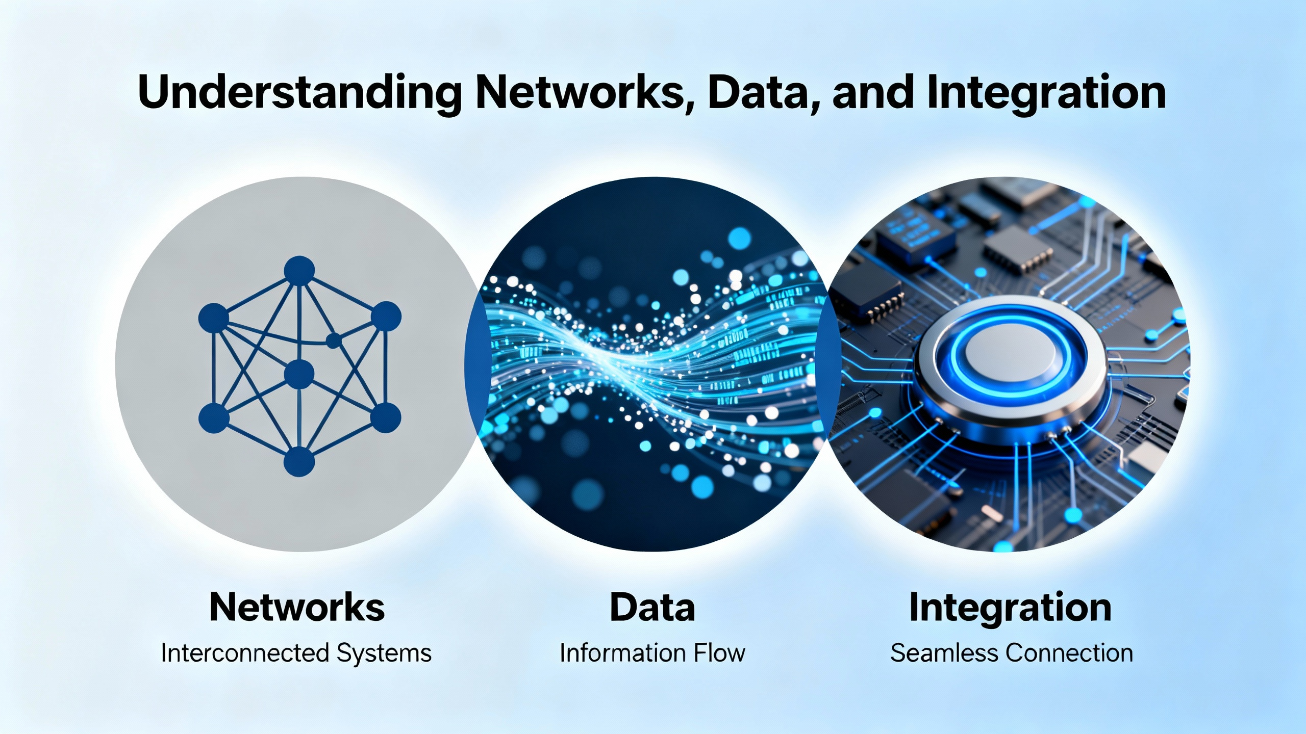
Networks, Data, and Integration
Modern motion controllers almost never operate in isolation. They talk to HMIs, PLCs or supervisory controllers, other motion controllers, and plant‑level or cloud‑level systems. Tech Briefs outlines three broad families of communication mechanisms:
Ethernet‑PLC oriented fieldbuses, such as EtherNet/IP, Profinet, EtherCAT, and SERCOS III.
Ethernet‑PC oriented mechanisms, such as UDP and HTTP.
Other methods including Web servers, SD card logging, FTP, and VPN‑style remote access.
For multi‑axis coordination, several points are worth stressing.
Modbus TCP operates as a non‑deterministic Ethernet protocol, with typical two‑device update times in the range of 20 to 500 ms. That is rarely suitable for closing tight motion loops, but it is perfectly reasonable for configuration, status, and slower process variables.
EtherNet/IP is widely used for its flexible I/O models, and Tech Briefs notes that it can achieve update rates as low as around 10 ms in practice, with many applications operating between about 30 and 100 ms. Again, that is acceptable for many supervisory tasks, but not for sub‑millisecond interpolation.
UDP has very low overhead and can deliver updates on the order of 1 to 4 ms between PC‑based systems and motion controllers. Vendors often provide function blocks on the PLC side to decode packets into motion parameters.
EtherCAT with CANopen over EtherCAT, as that same source describes, is designed for deterministic, cyclic process data exchange. Update times near 0.25 ms are common for process data objects, with slower service data transfers for configuration.
When you choose a motion controller for multi‑axis coordination, you are effectively also choosing a network ecosystem. In practice, that means:
Confirming that the controller supports the fieldbus used by your chosen drives.
Making sure the controller can also handle higher‑level communication needs without choking the motion engine.
Planning how HMIs, SCADA, and IIoT connectivity will share ports and bandwidth with motion traffic.
Tech Briefs makes a practical point here: motion controllers often host built‑in Web servers, log to SD cards, and act as data sources for external PCs. Those features are valuable, but they are not free in terms of network load. Good system design considers them from the start rather than bolting them on late in the project.
Safety, Reliability, and Lifecycle
For multi‑axis machines, safety and reliability are as important as motion quality. Control Engineering’s guidance on selecting controllers stresses that you must match controller type not just to cycle time and I/O scale, but also to safety, environment, and lifecycle.
On the safety side, common patterns include safety PLCs supervising safety‑rated drives, and PACs that integrate safety and standard control in one platform. In both cases, you need to check that the safety functions meet required performance levels, and that safety loop execution rates and communication latencies are compatible with your risk analysis. For complex multi‑axis systems, integrated safety over the same industrial Ethernet network that carries motion commands is increasingly common. That allows controlled safe speed and safe motion zones instead of brute force shutdown.
On the reliability and lifecycle side, there is a stark difference between industrial controllers and commodity PCs, as Automate points out. PLC and drive vendors often commit to supporting products for twenty years or more. PC motherboards may be gone in a fraction of that time. When you choose PC‑based soft motion for multi‑axis coordination, you are also choosing a strategy for replacing that hardware in a controlled way over the life of the machine.
Environment matters as well. AutomationDirect and Control Engineering both cite typical controller operating ranges around 30 to 130 °F. If your controllers live in hot, dusty enclosures near ovens or outdoors in winter, you may need hardware specifically rated beyond those conditions. Ignoring that on a high‑speed multi‑axis machine is an invitation to intermittent faults that are extremely hard to troubleshoot.
Sizing, Mechanical Dynamics, and Controller Implications
Anaheim Automation’s motor sizing guidance is aimed at motors and drives, but the underlying principles are critical for controller selection in multi‑axis systems as well.
Required power is the product of torque and speed. Getting that right eliminates motors that are underpowered or wildly oversized. Once you know power, you calculate system inertia and keep the ratio of load inertia to motor rotor inertia within roughly thirty to one for many motor types, or closer to ten to one for stepper motors. If the ratio is higher, you either increase motor size or introduce a gearbox to achieve mechanical advantage.
The selection of gearing versus larger direct‑drive motors is not just a mechanical question. Anaheim Automation notes that gearheads are relatively bulky and expensive, but provide the mechanical leverage necessary for heavy loads. A larger direct‑drive motor and driver may be simpler physically, but change the electrical power and current demands on your controller and drive ecosystem.
They also recommend a torque margin of at least fifty percent over the calculated minimum to account for friction changes, wear, disturbances, and resonance. Margins much above one hundred percent usually add cost without much benefit. In real multi‑axis machines, friction, inertia, and resonance behaviors shift once the motors are bolted to real loads, so they advise expecting some iteration.
For a motion controller in a multi‑axis system, these factors show up as:
Peak and continuous current capabilities of the drives and any integrated amplifiers.
Available bus voltage and current, whether that is single‑phase 110 VAC, 220 VAC, DC supplies, or batteries, which Anaheim Automation highlights as significant constraints.
The need for the controller to execute profiles with realistic acceleration and deceleration rates given that torque and inertia, without saturating and losing control.
If your mechanical system is marginally sized, the controller will spend its life fighting it. You may still be able to hit positions, but not on time or without excessive settling. It is far cheaper to correct that earlier in design by following the selection practices described by Anaheim Automation and others, than to try to “tune your way out” at commissioning.
Tools, Programming Environment, and Team Capability
In multi‑axis systems, the programming environment is as important as the raw controller hardware. Control Engineering and AutomationDirect both argue that families of controllers sharing a common programming environment across several sizes are a practical way to avoid painting yourself into a corner.
If a vendor’s small, medium, and large CPUs all use the same IEC 61131‑3 toolchain and motion libraries, you can prototype your eight‑axis machine on a mid‑range controller and later move to a larger CPU if performance or I/O demands increase, without rewriting the code from scratch. This also simplifies using multiple smaller controllers for modular machine sections while maintaining a single code base.
Look for:
Standardized motion function blocks aligned with PLCopen so your team is not reinventing basic moves and homing sequences.
Built‑in support for features like PID loops, floating point math, drum sequencing, interrupts, subroutines, and real‑time clocks, which Control Engineering notes are often missing in lower‑end controllers.
Good diagnostics, data logging, and integration with HMIs, so that during commissioning and maintenance you can see what each axis thinks it is doing, not just whether a bit is on.
AutomationDirect’s guidance emphasizes practical steps such as creating detailed I/O spreadsheets, including analog and specialty modules, and leaving about twenty percent I/O headroom for future expansion. For multi‑axis systems, treat motion axes themselves in the same way. If you think you need ten axes, and the controller tops out at ten, you already know what will happen in the next product meeting.
A controller family with scalable CPUs, common software, and good diagnostic tools does more than save engineering hours. It makes you a better long‑term partner for your own operations or your customers because you can support and evolve the machine for years instead of treating each variant as a new platform.
A Practical Example: Coordinated Packaging Line
To pull this together, consider a packaging machine with eight servo axes. Four axes form a synchronized infeed that must follow the belt and adjust position based on vision data. Two axes form a gantry that picks and places product into cartons. Two more axes operate a synchronized sealing mechanism.
The mass, move, and means analysis tells you that:
All eight axes need coordination in groups, and the infeed and gantry must share timing so product is available at the right place and time.
Cycle time is aggressive; suppose you are somewhere near the 200 ms per cycle example discussed earlier, with image‑based corrections and fast moves.
The machine must log production data and integrate with plant systems, but motion performance has priority.
In that situation, I would rarely trust smart drives alone for coordination. A high‑end PLC or PAC with strong motion features, or a dedicated motion controller paired with a PLC, is more appropriate.
You would likely centralize interpolation and position loop closure for the infeed and gantry axes in the motion controller. Velocity and current loops would run in the drives. EtherCAT or a similar deterministic fieldbus with sub‑millisecond cyclic updates would make sense for the drive network. Supervisory communications to the plant might use EtherNet/IP or Modbus TCP at tens of milliseconds update rates through a separate logical channel or port, per the patterns described in Tech Briefs.
You would select motors and drives following Anaheim Automation’s guidance on torque, speed, inertia ratio, and torque margin, then confirm that the motion controller can generate the required profiles without saturating.
Finally, you would choose a controller family and software environment that allows you to scale up to more axes or split the machine into modules in future revisions, echoing the recommendations from AutomationDirect and Control Engineering on using scalable platforms.
FAQ
Do I always need a dedicated motion controller for multi‑axis coordination?
Not always. Automate and Motion Control Tips both show that high‑end PLCs or PACs with integrated motion can now handle interpolation and coordinated motion that once required stand‑alone motion controllers. For modest axis counts and moderate dynamics, an integrated PLC or PAC can be the most practical choice. Dedicated motion controllers come into their own when you need extreme precision, very fast loops, complex kinematics, or very high axis counts.
How should I decide between centralized and distributed motion control?
Treat it as a loop‑by‑loop decision. Motion Control Tips recommends keeping high‑bandwidth loops such as current and commutation in drives, while higher‑level functions like interpolation and coordinated position loops stay centralized for multi‑axis work. Use distributed intelligence in drives to simplify wiring and improve local performance, but avoid pushing fast, tightly coupled loops across networks whose latency and jitter you cannot control.
What is the most common mistake in multi‑axis controller selection?
The mistake I see most often is treating the motion controller as an afterthought once mechanics and motors are “done.” The sources cited here repeatedly stress the opposite: start with the application, define the axis interactions, timing, and performance requirements, and then pick the architecture and controller. It is very difficult and expensive to retrofit a different architecture or motion platform once the machine is mostly designed.
In multi‑axis systems, picking the right motion controller is less about chasing features and more about fit for purpose. When you anchor your decision in the application’s mass, moves, and means, and you respect the real‑time and coordination realities described by Automate, Motion Control Tips, Tech Briefs, Anaheim Automation, AutomationDirect, and Control Engineering, you end up with machines that run predictably, can be supported for the long haul, and make you the partner people call back for the next project.
References
- https://ww2.jacksonms.gov/virtual-library/97oU2a/5OK100/advanced-motion__controls__manual.pdf
- https://www.automate.org/motion-control/industry-insights/how-to-specify-a-controller-for-your-motion-system
- https://blog.mide.com/fundamentals-motion-control-system-infographic
- https://library.automationdirect.com/how-to-choose-an-industrial-automation-controller-2/
- https://www.controleng.com/how-to-choose-an-industrial-automation-controller/
- https://www.csemag.com/how-to-select-a-building-automation-system/
- https://www.india.fujielectric.com/blog/a-guide-to-choosing-the-right-industrial-automation-controller
- https://www.linkedin.com/pulse/choosing-right-motion-control-technology-maximizing
- https://www.machinedesign.com/motorsdrives/case-retrofitting-advanced-motion-controllers
- https://modernpumpingtoday.com/how-to-choose-an-industrial-automation-controller/
Keep your system in play!
Top Media Coverage
Categories


Related Products
-
 Control ModuleManufacturer: General Electric
 -
ENCODERManufacturer: NTRON
-
POINT INPUT MODULEManufacturer: Allen-Bradley
-
 ISOLATED ANALOG MODULEManufacturer: Woodward
 -
Dc Pitch ConverterManufacturer: General Electric
-
EPROM Set developedManufacturer: General Electric
-
 Simplex Contact Input Terminal BoardIn StockManufacturer: General Electric
 -
3300 NSv Proximity ProbesManufacturer: Bently Nevada
-
Control ModuleManufacturer: General Electric
-
Industrial Ethernet SwitchManufacturer: NTRON

Related articles Browse All
-
 amikong NewsSchneider Electric HMIGTO5310: A Powerful Touchscreen Panel for Industrial Automation2025-08-11 16:24:25Overview of the Schneider Electric HMIGTO5310 The Schneider Electric HMIGTO5310 is a high-performance Magelis GTO touchscreen panel designed for industrial automation and infrastructure applications. With a 10.4" TFT LCD display and 640 x 480 VGA resolution, this HMI delivers crisp, clear visu...
 -
 BlogImplementing Vision Systems for Industrial Robots: Enhancing Precision and Automation2025-08-12 11:26:54Industrial robots gain powerful new abilities through vision systems. These systems give robots the sense of sight, so they can understand and react to what is around them. So, robots can perform complex tasks with greater accuracy and flexibility. Automation in manufacturing reaches a new level of ...
 -
 BlogOptimizing PM Schedules Data-Driven Approaches to Preventative Maintenance2025-08-21 18:08:33Moving away from fixed maintenance schedules is a significant operational shift. Companies now use data to guide their maintenance efforts. This change leads to greater efficiency and equipment reliability. The goal is to perform the right task at the right time, based on real information, not just ...


- Q&A
- Policies How to order Part status information Shipping Method Return Policy Warranty Policy Payment Terms
- Asset Recovery
- We Buy Your Equipment. Industry Cases Amikong News Technical Resources Why choose us
- ADDRESS
-
 32D UNITS,GUOMAO BUILDING,NO 388 HUBIN SOUTH ROAD,SIMING DISTRICT,XIAMEN
Leave Your Comment