
-
Please try to be as accurate as possible with your search.
-
We can quote you on 1000s of specialist parts, even if they are not listed on our website.
-
We can't find any results for “”.
Closed-Loop Stepper Systems with Encoder Feedback: A Practical Guide from the Integration Floor
When you run real production lines, you do not care whether a drive is called “smart,” “hybrid,” or “next‑gen.” You care whether the axis hits its mark, every time, without cooking itself or blowing your downtime budget. Over the last decade I have seen one technology quietly become the workhorse in that middle ground between cheap open‑loop steppers and full servo drives: closed‑loop stepper systems with encoder feedback.
Vendors from Nanotec, PMD, Galil Motion Control, PBC Linear, SANYO DENKI, and others have published enough hard data to move this out of marketing territory. Properly applied, closed‑loop steppers eliminate step loss, cut heat, smooth velocity, and let you run closer to the edge without falling off. This article walks through how they work, what the control loop really does, where they beat both open‑loop steppers and servos, and how to specify them so they behave in your plant, not just in a brochure.
From Open Loop to Closed Loop: Why Feedback Matters
Controls engineers have used closed‑loop systems for decades in everything from thermostats to CNC. TechTarget and other references describe the pattern clearly. A closed‑loop control system measures actual output with sensors, compares it to a desired setpoint, calculates an error, and drives actuators to reduce that error. That loop runs continuously so the system can reject disturbances and hold the target state without an operator riding the knobs.
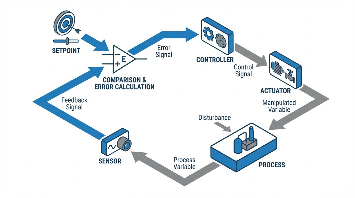
In an open‑loop system there is no feedback. The controller sends commands and assumes the mechanism obeys. A simple time‑based heater is a classic analogy: it turns on for ten minutes every hour regardless of room temperature. A closed‑loop thermostat, in contrast, watches temperature and switches heat only when needed.
Stepper drives began life very much on the open‑loop side. The controller sends step and direction pulses, and each pulse advances the motor by one step or microstep. As long as no steps are missed, you know where you are just by counting pulses. That simplicity is why steppers became ubiquitous in 3D printers, small CNC routers, and packaging machines.
The trouble starts when the real world pushes back. Load spikes, jams, friction, and resonance can cause the motor to miss steps. With no feedback, the controller has no idea anything went wrong. Over a shift those missed steps turn into misaligned labels, bad cuts, or parts that no longer line up under a tool.

Closed‑loop stepper systems keep the basic stepper hardware but wrap it in a feedback loop, usually using an encoder. That feedback is what turns a “dumb” stepper into something much closer to a servo, while keeping the high low‑speed torque and straightforward integration that made steppers popular in the first place.
How an Open-Loop Stepper Really Behaves
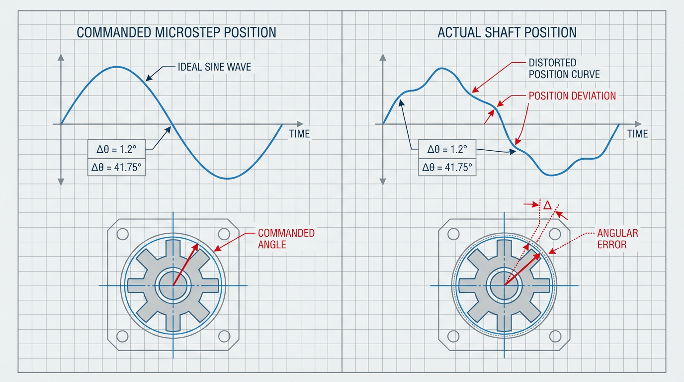
Standard stepper motors divide a revolution into discrete steps, often around two hundred full steps per turn. Drives can microstep, dividing each full step into many microsteps, sometimes up to fifty‑one thousand two hundred microsteps per revolution according to data discussed by RoboticsTomorrow. That gives very fine commanded resolution and smooth motion at low speed.
The advantages are obvious on paper. Steppers deliver high torque at low speeds, hold position firmly when energized, and are easy to control with simple step and direction signals. Circuit Specialists and Automate.org both emphasize how attractive this is for low‑cost positioning, light automation, and lab gear.
The limitations show up under stress. Source Robotics notes that engineers routinely oversize steppers by twenty to fifty percent simply to avoid stalls and step loss near the torque limit. Open‑loop drives often run at constant rated current, even at standstill, which wastes power and generates heat. RoboticsTomorrow and Galil Motion Control highlight resonance and vibration at particular step frequencies, which not only sound bad but can shake parts and contribute to lost position. And microstepping itself does not guarantee accuracy; the RoboticsTomorrow analysis points out that static friction and gravity can leave the final shaft position off by as much as a full step, even if you commanded many microsteps.
So open‑loop steppers are great when loads are predictable, speeds are moderate, and an occasional lost step is tolerable. When you need repeatable positioning under varying loads, or you cannot tolerate hidden errors, you either overspend on steppers and hope, or you move to feedback.
What Changes in a Closed-Loop Stepper System
At a high level, a closed‑loop stepper system looks like any other feedback axis. You still have a stepper motor and a drive. What you add is a position sensor, usually an encoder, plus control algorithms that compare commanded and actual position, speed, or torque and adjust the drive currents accordingly.
Nanotec describes a typical implementation as sine‑commutated, field‑oriented control. The encoder feeds back rotor position, the controller calculates a sinusoidal current set for each phase to keep the stator field nearly perpendicular to the rotor, and a current loop enforces that command. That is essentially servo control applied to a two‑phase stepper instead of a three‑phase brushless motor.
Galil and PMD both emphasize that true closed‑loop stepper control is not just counting steps and glancing at the encoder now and then. The controller runs a real position loop, often PID with additional filters, at several thousand cycles per second. PMD’s motion‑control chipsets operate in the ten to twenty thousand cycles per second range, which is enough to perform commutation, position control, and field‑oriented current regulation in real time.
Forms of Closed-Loop Stepper Control
The industry has converged on a few main control strategies for adding feedback to steppers. RoboticsTomorrow, Galil, LinearmotionTips, and Source Robotics describe these in different terms, but they all fall into three families.
The simplest is end‑point correction or step‑loss compensation. The motor runs mainly like an open‑loop microstepping system. At the end of a move, the controller compares commanded position to encoder position and, if there is a discrepancy, it issues extra steps to pull the load into tolerance. This is relatively easy to bolt onto existing step‑and‑direction interfaces and is useful when only final position matters. The downside, as LinearmotionTips notes, is that correction happens only at the end of motion, not during the move, so dynamic performance and stall behavior do not improve much.
The next level is continuous closed‑loop microstepping, sometimes called load‑position control. Here, the controller continually monitors encoder position while still generating step‑like commands internally. An error signal drives small adjustments to microstep timing so the motion profile follows the encoder, not just the step count. RoboticsTomorrow highlights that this is a true closed loop during motion and improves tracking, but it still tends to be less efficient than full servo control and must be tuned carefully to avoid instability.
The most capable approach is full servo‑style control of the stepper, often using field‑oriented control as described by Nanotec, PMD, and Source Robotics. The controller does not think in step pulses any more. Instead, it commands torque based on position and velocity error, just as it would for a brushless servo. The stepper becomes, in PMD’s phrase, a two‑phase brushless motor with an encoder. This mode delivers the highest efficiency, torque utilization, and speed while still taking advantage of the stepper’s high low‑speed torque and holding behavior.
The following table summarizes these modes in practical terms.
| Control mode | How it works in practice | Typical use case |
|---|---|---|
| End‑point correction | Runs open‑loop microstepping; compares encoder and steps at the end; adds extra steps | Applications where only final position matters and you want insurance against step loss |
| Continuous closed‑loop microstep | Monitors encoder during motion; tweaks microsteps to follow commanded trajectory | Better tracking and reliability without completely changing existing drive architecture |
| Servo‑style FOC on stepper | Encoder‑based commutation and PID/FOC torque control, no step pulses | Highest performance and efficiency where step loss is unacceptable and dynamics matter |
Encoder Feedback: Giving the Stepper Reliable Eyes
A closed‑loop system is only as good as its feedback. In stepper applications that typically means an encoder, though articles from Casun, Xinje, and Automate.org also describe resolvers and magnetoresistive sensors for specific environments.
Optical encoders are the workhorse. Automate.org’s discussion of closed‑loop stepper functionality points out that incremental optical encoders can easily reach sixty‑five thousand pulses per revolution, while absolute optical encoders can reach around twenty bit resolution, meaning more than one million uniquely addressable positions per turn. PBC Linear’s StepSERVO example uses a twenty thousand count encoder and reports substantial gains in positional precision and repeatability.
Magnetic encoders and Hall‑effect sensors trade some resolution for robustness and cost. Automate.org notes that many magnetic and Hall solutions do not match the effective resolution of a two‑hundred‑step motor across a full revolution, which can matter if you want the encoder to see every microstep. Casun describes magnetoresistive sensors as another magnetic‑field‑based option with different cost and robustness tradeoffs.
Resolvers, which Xinje highlights in the servo context, offer analog position feedback that is exceptionally robust to temperature and contamination. Their resolution is often comparable to Hall‑based solutions, but they shine in harsh environments where an optical disc might not survive.
In practice, the choice comes down to how much resolution you genuinely need, how dirty and hot the environment will be, and what failure modes you can tolerate.

For precision positioning in semiconductor tools or test equipment, high‑resolution optical encoders from vendors like Nanotec’s ecosystem are often the right choice. For rugged actuators on the edge of a packaging line or a clinical analyzer that sees wash cycles, a sealed magnetic encoder or resolver may be the better risk tradeoff.
What the Data Actually Shows: Performance Gains
Published tests and application notes give a concrete picture of what closed‑loop steppers deliver beyond marketing promises.
On torque and speed, PBC Linear reports that its StepSERVO closed‑loop stepper design increases available torque by about eighty‑five percent at speeds below roughly seven hundred fifty revolutions per minute, while actually consuming less power than a comparable open‑loop stepper drive. Nanotec notes that closed‑loop stepper solutions can deliver high torque without gearboxes up to around five hundred revolutions per minute, which covers a large portion of industrial positioning tasks.
PMD’s analysis of closed‑loop steppers shows that for the same motor, running it in servo mode with encoder feedback can yield approximately two to three times higher effective acceleration compared with open‑loop microstepping. Their case study describes a motor accelerating from standstill to about thirty revolutions per second and back to zero in a few milliseconds with only a few encoder counts of following error when driven in closed loop.
On motion quality, Galil Motion Control’s tests are especially instructive. Using the same linear stepper, they compared open‑loop microstepping against closed‑loop control with encoder feedback. In open loop, the measured velocity exhibited a sinusoidal ripple of about plus or minus five hundred encoder counts per second. Switching to closed‑loop control with tuned PID reduced that ripple to about plus or minus sixty counts per second. Adding a notch filter to target the natural resonance around sixteen hertz cut the ripple further to about plus or minus fifteen counts per second.
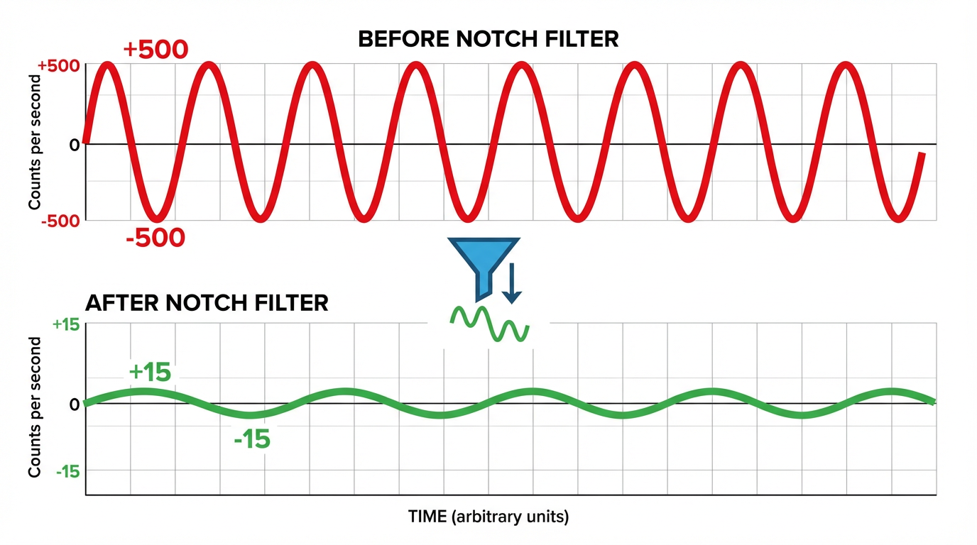
Subjectively, the audible pulsing characteristic of open‑loop microstepping nearly disappeared.
Thermal behavior and efficiency follow the same pattern. In Galil’s test, both motors ran at the same commanded speed and load. After a half hour, the closed‑loop axis ran about twelve degrees Fahrenheit cooler at the case than the open‑loop axis under the same ambient conditions, indicating significantly lower current and copper losses. Source Robotics estimates that servo‑style field‑oriented control on steppers can improve efficiency by as much as six times and enable roughly four times the top speed compared with traditional open‑loop drives, while also reducing resonance and extending motor life.
A number of sources, including Nanotec, Circuit Specialists, and JSS Motor, stress the accuracy story. Because the encoder measures rotor position directly, closed‑loop steppers are no longer constrained by the inherent step angle for accuracy. PMD notes that with suitable encoders, closed‑loop systems can reach usable resolutions from a few thousand up to around one million positions per revolution. Nanotec and JSS Motor both emphasize that the continuous position correction essentially eliminates step loss and cumulative position drift, which is exactly what you want in CNC axes, medical dosing pumps, and robotic joints.
Finally, closed‑loop steppers are quieter and calmer mechanically. Nanotec and Motion Control Technology articles describe very low resonance and what one vendor terms “zero micro‑vibration” at standstill. PI, which focuses on precision stages, points out that stepper‑driven axes can hold a commanded position without the hunting or dithering that servo systems sometimes exhibit around a setpoint, improving in‑position stability for sensitive optical or measurement tasks.
Closed-Loop Stepper vs. Open-Loop Stepper vs. Servo
From an integrator’s perspective, the right question is not whether closed‑loop steppers are “better,” but where they sit in the toolkit relative to traditional steppers and full servos. Drawing on comparisons from Automate.org, Nanotec, Festo, PMD, and others, the tradeoffs line up roughly as follows.
| Aspect | Open‑loop stepper | Closed‑loop stepper with encoder | Servo motor system |
|---|---|---|---|
| Position feedback | None; assumes every step is executed | Encoder or sensor feedback; corrects errors in real time or end‑point | High‑resolution encoder or resolver with fast servo loop |
| Torque behavior | High at low speed; drops quickly at higher speed | High low‑speed torque; better usable torque at moderate speed | Flatter torque over wide speed range |
| Efficiency and heat | Constant high current; runs hot and wastes energy | Current on demand; cooler and more efficient | Current on demand; typically efficient and cool |
| Complexity and tuning | Simple drives; minimal tuning | More complex drives; some tuning for PID and filters | Highest complexity; tuning required for each axis |
| Cost | Lowest hardware cost | Moderate; encoder and smarter drive add cost | Highest per‑axis cost |
| Typical sweet spot | Simple, predictable, low‑speed tasks | High‑torque, low‑to‑mid‑speed axes where step loss is unacceptable | High‑speed, high‑throughput, variable‑load applications |
Festo explicitly positions closed‑loop steppers for cases where open‑loop solutions no longer provide enough reliability or accuracy, but full servo systems feel unnecessarily complex and expensive. Nanotec makes a similar argument, noting that closed‑loop steppers combine the high low‑speed torque and fast settling of steppers with servo‑like efficiency and smoothness.
Automate.org’s comparison of servo and stepper systems reminds us that servos still win when you need continuous high‑speed motion, broad torque bandwidth, and multi‑axis coordination under highly dynamic loads, such as complex robotics or high‑speed packaging. At the other end, open‑loop steppers remain a great fit for inexpensive benchtop equipment where a lost position now and then is an annoyance, not a disaster.
Closed‑loop steppers fill the gap. They are compelling when you need stepper‑class torque and simplicity, but you cannot live with hidden step loss, excess heat, or long tuning cycles.
Where Closed-Loop Steppers Shine on Real Machines
The application examples from Motion Control Technology, Nanotec, Casun, Circuits Specialists, JSS Motor, and others line up with what I see in projects.
In robotics and handling, closed‑loop steppers are an excellent fit for articulated arms, compact Cartesian systems, and pick‑and‑place heads where axes must move quickly, stop precisely, and repeat all day without creeping out of position. Motion Control Technology highlights robotics and packaging as prime targets. Nanotec describes closed‑loop multi‑axis solutions using serial, Ethernet, or industrial fieldbuses for tasks such as semiconductor handling and inspection.
In packaging and labeling machines, you often need high low‑speed torque for feeders, knives, and seal bars plus precise registration against an encoder or sensor on the moving product. Automate.org’s servo versus stepper case studies show servo‑based machines hitting the highest speeds, but closed‑loop steppers offer a strong middle ground on smaller or cost‑constrained equipment. They remove the need to oversize motors just to survive a rare jam or heavier product.
Medical and laboratory devices benefit from the quiet, cool, and precise characteristics. Motion Control Technology and Circuits Specialists both emphasize how closed‑loop steppers improve smoothness and positional integrity in syringe pumps, analytical instruments, and other dosing systems where misplacing a few microliters is unacceptable. Galil and Nanotec note that lower heat and smoother torque are attractive in heat‑sensitive scientific instruments where airflow and vibration have to be tightly controlled.
In 3D printers, CNC tools, and small machine tools, Casun reports that closed‑loop control improves print accuracy, machining precision, and process stability. For CNC in particular, Radonix and CNC‑focused sources outside the stepper domain show how feedback‑based control can cut machining errors dramatically compared with open loop. Closed‑loop steppers bring some of those servo‑class benefits into lower‑cost gantries and routers without changing the entire drive architecture.
Textile machines, coil winders, and tensioning systems are another stronghold. PMD points out that closed‑loop steppers, with their adjustable torque mode, behave almost like programmable springs. Nanotec describes torque‑mode operation where the motor holds a stationary load with a set force and then rotates when that force drops, ideal for winding and pressing processes. That combination of torque control and precise position feedback is tough to match with open‑loop drives.
Finally, in electronics and semiconductor tools, Motion Control Technology and Nanotec both highlight closed‑loop steppers in wafer handling, inspection stages, and light‑duty process tools. These applications value low vibration, low heat, and high repeatability over raw speed, which plays directly to the strengths of closed‑loop stepper technology.
Design and Integration Advice from the Trenches
Choosing a closed‑loop stepper is not just about picking a catalog part that says “encoder included.” A few practical steps make the difference between a reliable axis and yet another tuning project everyone dreads.
Start with the consequence of position loss. If losing position only causes a one‑off scrap part and the operator will notice immediately, open loop may still be acceptable. If step loss can silently ruin a batch, create safety risks, or force tedious re‑homing, you have a strong case for closed loop. Articles from Circuit Specialists, JSS Motor, and Casun are consistent on this point: eliminating step loss and hidden drift is the primary value.
Next, characterize the load and duty cycle honestly. Source Robotics and Nanotec both warn against assuming you can drive steppers right at their torque limits. Closed loop helps, but you still have to respect acceleration limits, inertia ratios, and friction. Look at your move profiles. If you need burst torque at low speeds, high holding torque at standstill, and only moderate top speed, closed‑loop steppers are in their element. If you need sustained high speed at significant torque, a full servo may still be the better fit.
When selecting feedback hardware, match encoder resolution to what the mechanics and controller can actually use. Automate.org’s stepper feedback discussion shows that if your encoder resolution is coarser than the motor’s full steps, you will not see every microstep, which limits how tightly the loop can control. On the other hand, PI’s analysis of stepper‑driven stages demonstrates that once microstep resolution gets finer than the mechanical system’s real capability, further increases do not improve performance. There is no point paying for a million counts per revolution if backlash, compliance, or bearing friction smear out the last few thousand counts.
Choose the control mode deliberately. If you already have a mature step‑and‑direction interface in your PLC and you simply want insurance against occasional lost steps, an end‑point correction drive like the “stepper position maintenance” described by Galil and RoboticsTomorrow might be a practical drop‑in. If you want real dynamic gains and smoother motion, move up to continuous closed‑loop microstepping or full servo‑style control as described by PMD, Nanotec, and Source Robotics.
Plan for tuning and diagnostics. Closed‑loop drives are more forgiving than full servos, but they are not magic. Galil’s work on adding notch filters to target a specific sixteen hertz resonance shows how much performance you can gain with modest tuning effort. nanotec and PMD both emphasize using built‑in tools to observe position error, current, and velocity during ramps so you can see what the axis is doing instead of guessing. Radonix’s CNC guidance on encoder quality and maintenance applies equally here: a noisy or loose encoder will undermine the entire loop.
Do not neglect power, wiring, and maintenance. Articles on CNC and motion control from Radonix and CNC Yangsen warn against underestimating power requirements or treating feedback wiring as an afterthought. Make sure your power supply can handle transient current demands, and route encoder and sensor cables to avoid electrical noise. Plan preventive maintenance around cleaning encoders, checking connectors, and logging any drive faults the way you already log PLC alarms.
Finally, think about system integration. Festo notes that many closed‑loop stepper systems support standard industrial buses and low‑voltage supplies in the twenty‑four to forty‑eight volt range, which simplifies safety and panel design. PMD’s motion‑control ICs can coordinate multiple axes, handle profiling, and manage both steppers and servos from a single architecture. If you are planning a machine platform rather than a one‑off retrofit, those integration details will matter more than the last percentage point of torque.
When Closed-Loop Steppers Are Overkill
As someone who has spent plenty of nights chasing phantom faults, I am biased toward feedback. But it is important to recognize when closed‑loop steppers are not the right answer.
If you are building simple, low‑speed mechanisms with predictable loads, where the cost of failure is low and you can easily re‑home axes, classic open‑loop steppers remain very hard to beat on cost and simplicity. Automate.org and Festo both reinforce that message.
At the other extreme, if your application demands high speed, complex multi‑axis coordination, and tight tolerance under fast load changes, full servo systems are still the gold standard. Servo motors with high‑resolution encoders and advanced drives, such as those discussed in Automate.org’s servo case studies, excel at tasks like high‑speed palletizing, long‑span gantries, or intricate multi‑axis machining where the dynamic envelope is simply beyond stepper territory.
Closed‑loop steppers occupy the middle ground where many real industrial applications live. They are a pragmatic way to harden stepper‑based designs against step loss, heat, and vibration without paying the full bill, in money or complexity, for a servo on every axis.
Closing Thoughts
Closed‑loop stepper systems with encoder feedback are not a shiny niche technology any more. They are a mature, well‑understood option with performance data from vendors like Nanotec, PMD, Galil Motion Control, PBC Linear, SANYO DENKI, Circuit Specialists, and others to back them up. If you are fighting step loss, oversized motors, hot drives, or touchy open‑loop tuning on your lines, it is probably time to put at least one axis on closed‑loop steppers and let the results speak for themselves. As a project partner, my advice is simple: use feedback where it buys you reliability and sleep, and let the steppers do what they do best—deliver solid torque and repeatable motion without drama.

References
- http://fab.cba.mit.edu/classes/865.18/motion/steppers/ieee-advanced-step-control-2017.pdf
- https://www.automate.org/motion-control/blogs/servo-system-vs-stepper-motor-solutions-for-precision-automation
- https://www.cncyangsen.com/understanding-cnc-closed-loop-system
- https://www.casunsteppermotor.com/news/application-of-closed-loop-control-in-improving-the-performance-of-stepper-motor-193288.html
- https://www.jssmotor.com/blog/what-are-the-benefits-of-using-a-closed-loop-stepper-motor806
- https://www.lafayette-engineering.com/understanding-controls-engineering-the-backbone-of-modern-automation/
- https://www.linearmotiontips.com/how-does-closed-loop-stepper-control-work/
- https://motioncontrol.blog/closed-loop-stepping-motors-precision-reliability/
- https://eureka.patsnap.com/article/what-is-a-closed-loop-control-system-and-how-does-it-work
- https://radonix.com/closed-loop-cnc-controller/
Keep your system in play!
Top Media Coverage
Categories


Related Products
-
 SERVO DRIVEManufacturer: Yokogawa
 -
 Analog Microprocessor BoardManufacturer: General Electric
 -
OPERATOR INTERFACEManufacturer: General Electric
-
D Cable Plus 1 meterManufacturer: Invensys
-
SERVO MOTORManufacturer: KOLLMORGEN
-
PROCESSOR VME SINGLE BOARDManufacturer: Motorola VME
-
CableManufacturer: Invensys
-
CableManufacturer: Invensys
-
POWER SUPPLYManufacturer: KONGSBERG
-
Circuit BoardManufacturer: Siemens

Related articles Browse All
-
 amikong NewsSchneider Electric HMIGTO5310: A Powerful Touchscreen Panel for Industrial Automation2025-08-11 16:24:25Overview of the Schneider Electric HMIGTO5310 The Schneider Electric HMIGTO5310 is a high-performance Magelis GTO touchscreen panel designed for industrial automation and infrastructure applications. With a 10.4" TFT LCD display and 640 x 480 VGA resolution, this HMI delivers crisp, clear visu...
 -
 BlogImplementing Vision Systems for Industrial Robots: Enhancing Precision and Automation2025-08-12 11:26:54Industrial robots gain powerful new abilities through vision systems. These systems give robots the sense of sight, so they can understand and react to what is around them. So, robots can perform complex tasks with greater accuracy and flexibility. Automation in manufacturing reaches a new level of ...
 -
 BlogOptimizing PM Schedules Data-Driven Approaches to Preventative Maintenance2025-08-21 18:08:33Moving away from fixed maintenance schedules is a significant operational shift. Companies now use data to guide their maintenance efforts. This change leads to greater efficiency and equipment reliability. The goal is to perform the right task at the right time, based on real information, not just ...


- Q&A
- Policies How to order Part status information Shipping Method Return Policy Warranty Policy Payment Terms
- Asset Recovery
- We Buy Your Equipment. Industry Cases Amikong News Technical Resources Why choose us
- ADDRESS
-
 32D UNITS,GUOMAO BUILDING,NO 388 HUBIN SOUTH ROAD,SIMING DISTRICT,XIAMEN
Leave Your Comment