
-
Please try to be as accurate as possible with your search.
-
We can quote you on 1000s of specialist parts, even if they are not listed on our website.
-
We can't find any results for “”.
Vector Control Sensorless Drives for Precision Speed Regulation
Why Precision Speed Regulation Matters
When you live in plants and panels as long as I have, you stop thinking about drives as catalog items and start thinking about them as process risks. A line running a web of plastic, a mixer feeding a batch reactor, a hoist holding a load overhead: in each case, speed regulation is not an abstract spec. It is product quality, mechanical wear, and sometimes safety.
Electric motor systems consume a huge share of the world’s electricity. Established literature summarized by GlobalSpec notes that motor systems account for roughly 45% of global electricity use and over 70% of industrial electricity. When so much energy and production throughput sits behind a variable frequency drive, getting torque and speed under tight control matters both economically and technically.
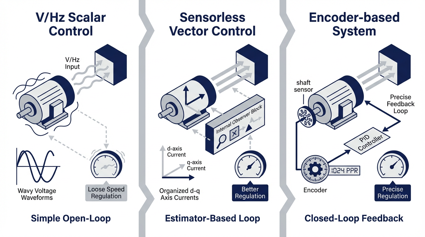
Historically, engineers had a simple choice. For pumps and fans, you used basic Volts-per-Hertz control and accepted loose regulation. For demanding axes, you paid for encoders and closed-loop vector or servo systems. Sensorless vector control changes that equation. It promises near-encoder performance in a lot of real applications without the cost and fragility of mechanical feedback. Used correctly, it delivers precise, repeatable speed regulation and strong low-speed torque while simplifying hardware. Used blindly, it can get you in trouble around zero speed or in safety-critical applications.
The goal of this article is to explain how sensorless vector drives actually work, where they shine, where they do not, and how to apply them pragmatically in industrial automation and control hardware.
From V/Hz to Vector: What Actually Changes
Scalar Volts-per-Hertz Control in Practice
Scalar or Volts-per-Hertz control is where many of us started. The drive outputs a three-phase voltage at a commanded frequency and keeps the V/Hz ratio roughly constant so the motor’s magnetic flux stays in a reasonable range. As described in discussions on the Mike Holt forum and Practical Machinist, that is essentially the whole story. The drive does not check whether the shaft is really turning at the expected speed or delivering the expected torque.
Under light to moderate load, scalar control works well enough. If the load increases, the motor slows slightly, slip increases, current rises, and torque increases in a somewhat uncontrolled way until the mechanical load and motor torque balance. This behavior is good enough for many centrifugal fans and pumps, but it is “sloppy” when you need precise, repeatable performance. Practical Machinist contributors note that scalar drives are really only comfortable over about a five-to-one or six-to-one speed range; below roughly 10 Hz of output frequency, accuracy and torque fall off quickly for most induction motors.
The key point is that scalar control manipulates only magnitudes: voltage and frequency.
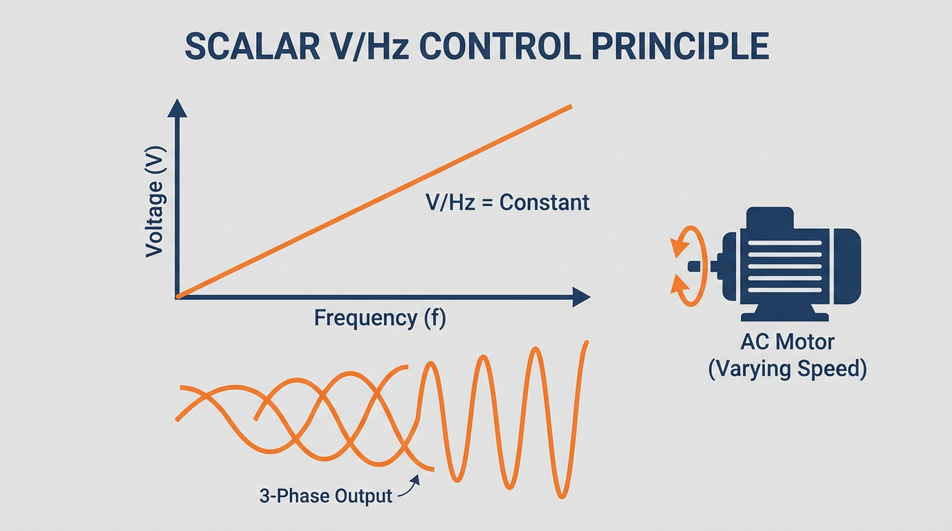
It does not control the magnetic flux vector inside the machine and does not directly control torque.
Encoder-Based Flux Vector Control
Vector or field-oriented control, by contrast, is fundamentally a flux control strategy. As explained in Control Engineering, Analog Devices technical articles, and several academic sources, the drive mathematically resolves the stator current into two components: one that produces flux and another that produces torque. In the common d–q model, the d-axis current sets the flux level and the q-axis current creates torque.
In a closed-loop flux-vector or field-oriented drive with encoder feedback, the inverter measures stator currents and shaft position, transforms currents into a rotating reference frame aligned with the rotor flux, and runs decoupled current loops for flux and torque. With a good motor model and a decent encoder, the drive can deliver full rated torque at zero speed, hold torque accurately during creep, and regulate speed very tightly across a wide range.
Real-world data summarized by Control Engineering and drive vendors show that such systems can achieve excellent speed regulation and dynamic response, approaching servo behavior for many applications. This is why encoder-based vector drives are a favorite for hoists, cranes, elevators, and high-precision motion where you absolutely must have controllable torque at zero speed before releasing a brake.

Sensorless Vector Control
Sensorless vector control (sometimes called open-loop vector) uses essentially the same vector control structure but removes the mechanical sensor. There is no encoder or resolver on the shaft. Instead, the drive estimates rotor speed and position from measured stator voltages and currents plus a motor model.
Forum discussions and vendor notes from AutomationDirect, KEB, and others all converge on the same picture. A sensorless vector drive is still a closed-loop system internally. It has fast current sensors, a mathematical model of the motor, and an observer that compares predicted electrical behavior with actual behavior. Deviations between the model and reality are used to adapt the estimated rotor speed and flux so the control loops stay synchronized with the true rotor state.
The payoff is attractive. You get DC-like torque at low speed and good speed regulation under changing load, without the encoder hardware, feedback cable routing, and associated failure points. However, because the drive cannot “see” shaft angle directly at true standstill, it cannot guarantee full rated torque at zero speed in the way an encoder-based system can. The Mike Holt discussion and KEB’s documentation both make this limitation explicit.
What “Sensorless” Really Means in Industrial Drives
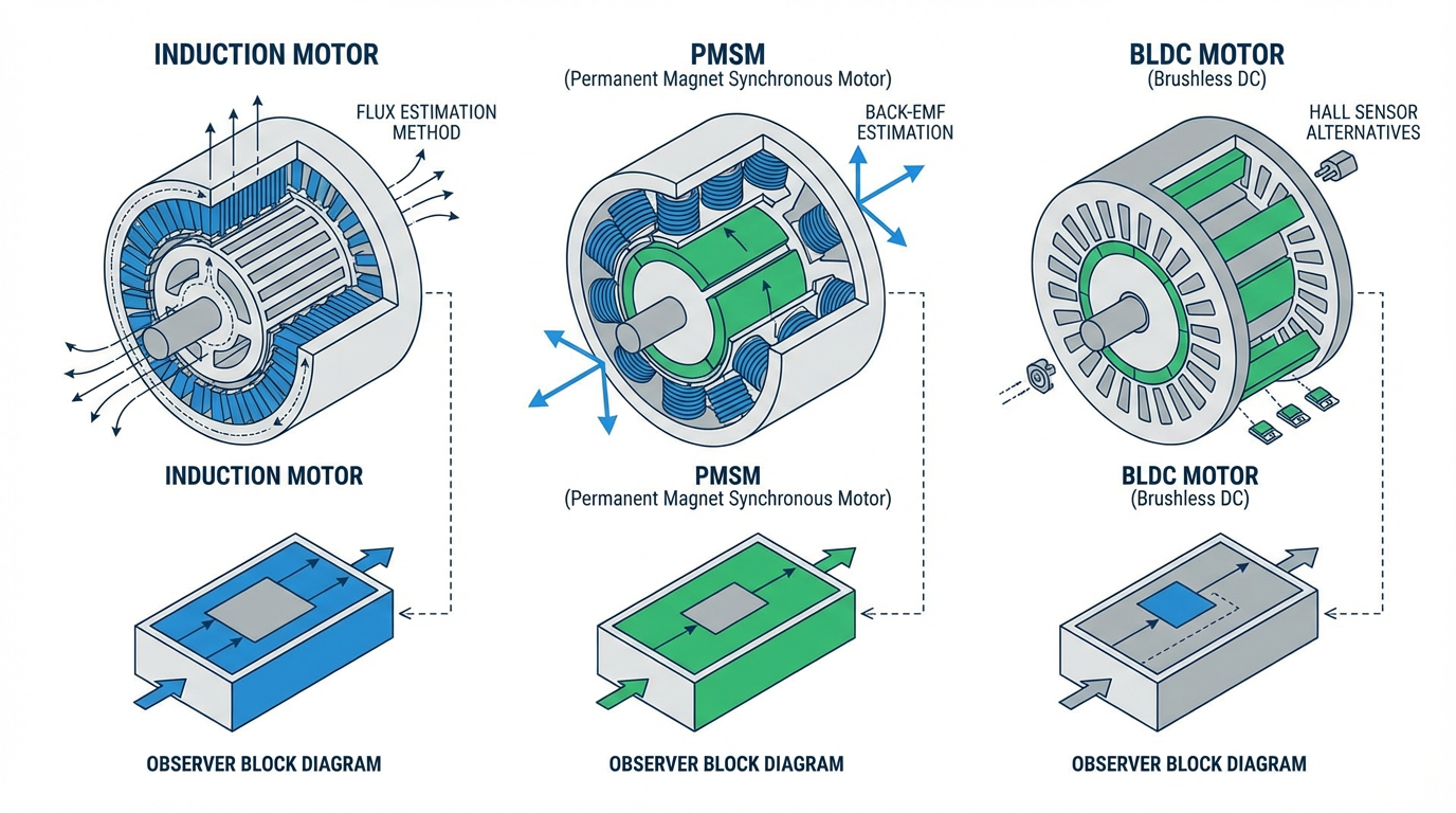
Induction Motors, PMSMs, and BLDCs
Sensorless drives apply to more than just induction motors. The GlobalSpec overview and Analog Devices articles highlight three main machine families where sensorless techniques are applied: induction motors, permanent magnet synchronous motors (PMSMs, including interior permanent magnet types), and brushless DC motors. All of these machines need rotor position information to run high-performance vector or direct torque control.
For induction machines, sensorless control typically estimates rotor flux and slip speed from stator currents and voltages using observers such as model‑reference adaptive systems or sliding-mode observers. The scholarsmine summary and other research abstracts emphasize that these methods are mature enough to be used widely in commercial induction motor variable-speed drives.
For PMSMs and BLDCs, rotor position is often estimated either from back electromotive force at medium and high speeds, or from saliency effects using injected test signals at low speed and standstill. The Cadence and Analog Devices articles describe how space-vector modulation and careful current shaping are used to reduce torque ripple and harmonics while enabling accurate position estimation across a wide speed range.
Categories of Sensorless Estimation
Technical literature summarized in the GlobalSpec brief and Analog Devices material groups sensorless methods into several families. At medium to high speed, back-EMF based methods work well because the induced voltage is large compared to noise and parameter uncertainty. Observers and extended Kalman filters can refine these estimates and filter noise effectively.
At low speed, back-EMF becomes too small. Parameter mismatches, especially stator resistance variation with temperature, start to dominate. To bridge this gap, some PMSM drive schemes inject high-frequency signals and exploit rotor saliency, especially in interior permanent magnet machines, to infer rotor position even at standstill. Other advanced methods combine multiple models or rely on distinctive inductance characteristics.
For induction machines in industrial drives, the dominant commercial methods are still based on fundamental-wave models rather than signal injection.
Research summarized from industrial surveys points out that these fundamental-wave sensorless schemes have been widely adopted because they balance robustness, cost, and implementation complexity better than many purely academic proposals.
In practical terms, “sensorless” in today’s industrial drives usually means a field-oriented or flux-vector control architecture with a motor model and estimator running on a modern DSP or microcontroller, using stator current and voltage measurements as its eyes and ears.
How Sensorless Vector Drives Regulate Speed and Torque
Motor Models, Observers, and DSP Power
Inside a sensorless vector drive, several layers of control work together. At the innermost level, the current controller shapes stator currents to follow d–q references. Just above that, a speed loop compares commanded speed to estimated speed and adjusts the torque-producing current reference.
To keep the rotating reference frame aligned, the drive runs an observer. Model-reference adaptive systems, Luenberger and sliding-mode observers, and extended Kalman filters all appear in the sensorless literature. In each case, a reference model and an adjustable model predict certain electrical quantities, and the difference between those predictions and measured quantities drives an adaptation law that updates the estimated rotor speed and flux.
Commercial application notes and Control Engineering articles emphasize how much progress comes from processing power. Faster microprocessors and mixed-signal controllers with high-resolution ADCs now let drives execute multiple observer models and advanced algorithms in real time. Analog Devices highlights that modern embedded controllers integrate DSP-class cores, digital filters, and math accelerators specifically to support sensorless vector control and to push efficiency closer to the theoretical limits.
In other words, the practical feasibility of sensorless precision speed regulation is tightly linked to the quality of the motor model, the robustness of the observer, and the capabilities of the silicon running them.

Low-Speed and Zero-Speed Behavior
Every engineer working with sensorless drives eventually runs into low-speed limitations. GlobalSpec’s review notes that back-EMF and model-based observers perform well at medium and high speeds but degrade at very low speeds because the signal-to-noise ratio collapses and parameter mismatches dominate. The result is that speed and position estimates become noisy or biased near standstill.
Drive vendors and forum contributors consistently warn that standard sensorless vector control cannot provide fully controllable rated torque at true zero speed in the same way encoder-based flux vector control can. KEB states explicitly that their sensorless closed loop is not intended for applications requiring full holding torque at zero speed because the algorithm depends on rotor movement to extract information from voltage feedback. The Mike Holt and Practical Machinist discussions echo the same recommendation: use encoder-based vector or servo control whenever zero-speed torque and position integrity are safety-critical.
That said, research examples show how far sensorless methods have come. An academic paper on “mirror-phase vector control” for salient-pole PMSMs reports the ability to deliver about 250% of rated torque at standstill, with stable control down to roughly one eighteen-hundredth of rated speed, while still operating up to rated speed. It also claims insensitivity to parameter variations and flux saturation, all without additional hardware beyond the basic inverter. These results are experimental, but they illustrate that, with sophisticated models and observers, the traditional low-speed limits of sensorless control can be pushed very far.
In day-to-day industrial work, however, most commercial sensorless vector drives are designed to deliver strong low-speed torque and good speed regulation over a wide but finite speed range, typically on the order of one hundred to one, but they still rely on some rotor motion for reliable estimation.

Real-World Benefits for Precision Speed Regulation
Dynamic Performance and Low-Speed Torque
Compared with scalar V/Hz control, the main reason to choose sensorless vector is dynamic performance. Control Engineering reports Baldor’s comparative testing of several sensorless vector drives from different manufacturers. They observed that full rated torque was available down to low speeds in the range of about 10 to 150 rpm, depending on the brand, with peak starting torque in the neighborhood of 160% to 200% of rated torque. Typical speed regulation was around one percent of base speed.
These results align with what many integrators see in the field. With sensorless vector, a conveyor can recover speed quickly after a product jam clears, a winder can hold tension by regulating speed tightly through load changes, and a mixer can maintain setpoint speed even as viscosity ramps up. KEB reports that their sensorless closed loop achieves dynamic response similar to encoder-based systems for many variable-load scenarios.
From a control perspective, this happens because the drive is no longer blind to torque.
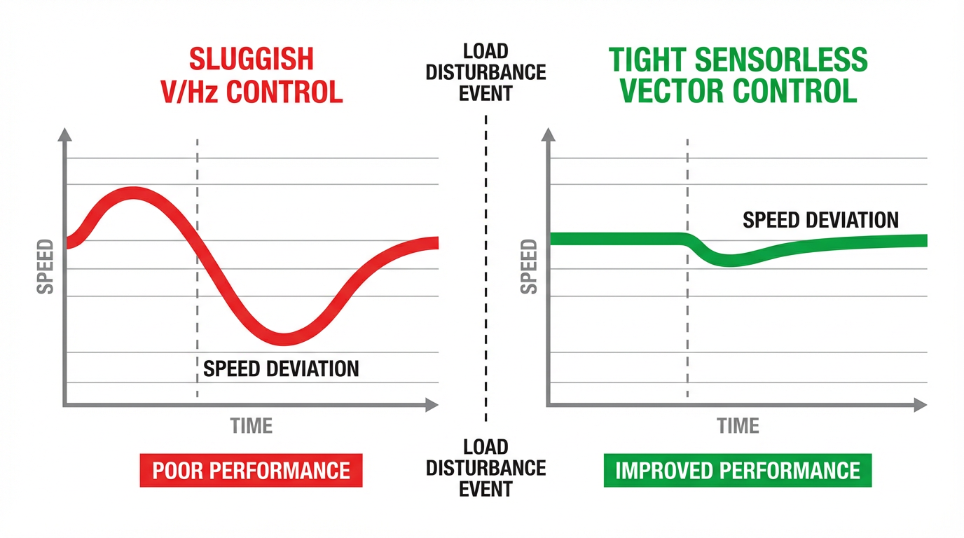
It is continuously adjusting the torque-producing current component to cancel speed error, rather than just hoping the V/Hz ratio yields enough slip to catch up.
Energy Efficiency and Cost Reduction
Energy efficiency is a second major lever. The Canroon brief on non-inductive vector control points out that HVAC systems using sensorless vector-controlled drives can save up to about 50% energy, and pumping systems commonly see savings in the 25% to 35% range when motors are controlled to match real process demand instead of running at fixed speed. These numbers reflect the combination of variable-speed operation and better torque control, which keeps motors out of inefficient operating points.
The economic impact is two-fold. First, you reduce electricity costs. Given the magnitude of industrial motor energy use highlighted by GlobalSpec and other sources, this reduction can be substantial over the life of a facility. Second, you reduce hardware costs by eliminating encoders, feedback cables, terminal boxes, and associated installation labor.
Industry surveys cited in Control Engineering and vendor literature underscore that lifecycle cost, rather than just purchase price, is the real driver behind the growth of sensorless vector drives. While the incremental cost between a basic V/Hz drive and a capable sensorless vector drive has shrunk, the savings from not installing, aligning, protecting, and maintaining encoders often outweighs any residual difference.
Reliability in Harsh Environments
Reliability is the third major benefit. Articles from Jayashree, GlobalSpec, KEB, and maxon all highlight that removing mechanical sensors improves robustness in dust, vibration, moisture, and high or low temperature conditions where encoders and Hall sensors struggle.
KEB points out that sensorless closed loop is particularly attractive where vibration and electrical noise are concerns, because it eliminates a vulnerable low-voltage feedback cable. Maxon’s discussion of sensorless BLDC control makes a similar argument for medical devices, space, and radiation-heavy environments where sensor electronics and connectors are hard to protect.
In my own projects, some of the most convincing wins for sensorless vector have come in sealed or hard-to-reach drives where you simply do not want another device on the shaft or another cable in the conduit. When you can get the speed regulation you need using only the power leads, it simplifies the entire system.

Limitations and Risks You Need to Respect
Sensorless vector is not a free lunch. Several limitations recur across both the research literature and vendor application notes.
Low-speed and standstill behavior is the most important. As already discussed, standard industrial sensorless vector drives should not be expected to deliver fully controllable rated torque at true zero speed. That makes them a poor fit for hoists, cranes, elevators, and any application where a mechanical brake is released only after full torque is confirmed on the motor. For those, encoder-based flux vector or a servo system should remain the default.
Parameter sensitivity is another concern. Scholarsmine and GlobalSpec both stress that sensorless estimators depend on accurate knowledge of stator and rotor resistances, inductances, and flux linkages, and must cope with magnetization saturation and inverter nonlinearities such as dead time and voltage drops. If the motor heats up, is rewound, or is replaced with a slightly different model without updating parameters, estimation accuracy and torque response can degrade.
At the system level, line conditions also matter. AutomationDirect warns that long motor cables in modern IGBT-based drives can create high-voltage ringing and reflective voltage that stress motor insulation and slightly distort drive output current, especially at low speed. Mitigation often involves keeping cable runs short where possible, using inverter-duty motors, and adding output reactors for cable runs above about 50 ft. These considerations apply to any VFD, but they are worth remembering when you are expecting precise behavior from a sensorless estimator based on electrical signals.
Finally, sensorless vector drives require more thoughtful setup than scalar drives. Control Engineering’s reporting on Baldor’s tests notes that sensorless vector units usually do not work at their best “out of the box” without entering motor information and performing some tuning, whereas basic inverters will at least rotate the motor with minimal input. Users who do not invest the small extra effort in commissioning sometimes blame the technology for what is really a configuration issue.
Choosing Between V/Hz, Sensorless Vector, and Encoder Feedback
When specifying drives, I find it useful to frame the choice in terms of application risk and performance demands rather than starting from a favorite technology. The following table summarizes the practical tradeoffs drawn from the sources above and day-to-day project work.
| Control method | Feedback hardware | Low-speed / zero-speed torque | Typical speed regulation | Typical applications | Main advantages | Main limitations |
|---|---|---|---|---|---|---|
| Scalar V/Hz | None | Weak below roughly 10 Hz, no zero-speed hold | Loose, speed varies with load | Fans, simple pumps, low-dynamic conveyors | Lowest cost and simplest commissioning | Poor low-speed torque, limited dynamic response |
| Sensorless vector (SVC) | Current and voltage sensors only | Strong low-speed torque, but not full rated at true zero speed | Around one percent of base speed in many products | General-purpose conveyors, mixers, HVAC, pumps, textiles, printing | Good dynamics without encoders, wide speed range, lower lifecycle cost | Needs accurate motor data and tuning, limited for safety-critical zero-speed torque |
| Encoder-based flux vector | Encoder or resolver | Full rated torque at zero speed possible | Comparable to servo for many loads | Hoists, cranes, elevators, precise positioning axes | Highest torque control quality, including at standstill | More hardware, wiring, and maintenance; higher installed cost |
These categories match recommendations found across multiple sources. GlobalSpec explicitly suggests simple V/Hz control for low-cost, low-dynamic loads such as fans and pumps, while encouraging advanced sensorless field-oriented control for high-dynamic drives in traction, robotics, and servo-like applications where encoders are undesirable. The Mike Holt forum and KEB documentation recommend encoder-based flux vector whenever zero-speed torque is critical.
In practice, my own decision path usually starts with three questions. First, what happens if the axis misbehaves or stalls. If the answer involves dropped loads or safety hazards, I default to encoder feedback. Second, how wide and how low does the operating speed range need to be while still maintaining regulation. If the process demands slow crawl speeds with torque regulation but not safety-critical holding torque, sensorless vector often fits well. Third, what is the realistic tolerance for added commissioning effort. If the operation is unwilling to enter motor data or run auto-tuning, scalar V/Hz may be the only honest choice despite its weaknesses.
Commissioning and Tuning: Lessons from the Field
Motor and Installation Basics
Before worrying about vector control algorithms, you need a solid electrical and mechanical foundation. AutomationDirect’s FAQ reminds us that any three-phase AC motor can be run from an inverter, but inverter-duty motors are recommended. They tolerate low-speed operation without overheating and handle the fast voltage edges of PWM drives better, consistent with NEMA and IEC motor standards for inverter-fed machines.
Proper motor grounding, appropriate VFD-rated cable for the motor leads, and attention to cable length and routing are not glamorous topics, but they directly impact noise, insulation stress, and ultimately the quality of the signals the drive uses for sensorless estimation. A drive fighting distorted measurements will not deliver precise speed regulation, no matter how advanced its algorithms.
Running Auto-Tune and Verifying the Model
Modern drives increasingly include auto-tuning and identification routines that extract motor parameters. Control Engineering notes examples such as Danfoss’s Automatic Motor Adaptation, ABB’s Direct Torque Control identification routines, and Siemens and Schneider Electric autotuning functions. GE Toshiba points out that additional sensors and better motor models have improved auto-tune accuracy and even allowed commissioning with only general motor parameters in some cases.
In the field, the practical advice is simple. Enter nameplate data carefully. Run the recommended auto-tune procedure, whether it is a standstill test that injects signals or a brief no-load spin. Then verify the model with some basic tests: check no-load current at rated speed, observe response to a small speed step, and examine behavior at low speed with moderate load. If something looks off, it is usually better to resolve the discrepancy at this stage than to compensate later with aggressive speed-loop gains.
Acceptance Testing for Precision Speed Regulation
Once the drive is commissioned, I like to prove out performance under conditions that resemble real operation rather than trusting catalog numbers. The Baldor tests summarized in Control Engineering provide a useful benchmark: full rated torque down to low rpm, average speed regulation around one percent of base speed, and starting torque around 160% to 200% of rated.
In a plant, I look for repeatability. If you command a low-speed setpoint and change the load, does the shaft speed settle consistently. Does the drive recover from a load disturbance without hunting or excessive overshoot. If you ramp through the speed range, do you see any unstable or noisy regions. For tension-sensitive processes, monitor the downstream effect, not just the motor shaft.
The point is not to turn every project into a lab experiment but to confirm that the specific combination of motor, drive, wiring, and mechanics behaves as the technology promises. Sensorless vector can deliver precise speed regulation, but real-world details dictate how close you get to that ideal.
Where the Technology Is Heading
Sensorless drive technology has been under intense research for decades, but several sources point out that only in recent years have certain advanced schemes moved from laboratory prototypes into commercial products. Industry surveys published in venues such as Industrial Electronics journals and ResearchGate note that only a subset of academic methods meet industrial requirements for robustness, computational burden, and ease of integration.
One current research direction is enriched observers, such as augmented model-reference adaptive systems enhanced with neuro‑fuzzy inference. The idea is to let a learning system capture nonlinearities and parameter variations that are difficult to represent in fixed equations, improving low-speed robustness and disturbance rejection in sensorless vector-controlled induction motors.
Another is signal-injection based sensorless control for PMSMs, which leverages machine anisotropy to extend high-quality position estimation all the way down to standstill. The mirror-phase vector control work mentioned earlier is an example of pushing sensorless PMSM performance to extremes of torque and speed range without extra hardware.
At the same time, semiconductor trends are pulling in the same direction. Analog Devices and others highlight that modern mixed-signal motor-control microcontrollers combine high-speed processing, high-resolution ADCs, and substantial on-chip memory. This enables running multiple estimators and control layers concurrently in relatively low-cost devices. GlobalSpec also notes a trend toward deeper integration of sensorless algorithms into dedicated motor-control ICs and broader adoption in electric vehicles, HVAC, industrial automation, and renewable energy systems.
For end users and integrators, the message is that sensorless vector technology will keep improving. Algorithms that once required specialist DSPs and careful hand-tuning are increasingly packaged as standard drive features, with auto-tuning and self-commissioning to hide much of the complexity.
Frequently Asked Questions
Can a sensorless vector drive replace every encoder-based system
Not yet, and in some cases it should not. For applications that demand full, controllable rated torque at zero speed, such as hoists, cranes, and safety-critical vertical axes, encoder-based flux vector or servo systems remain the standard. Both KEB and forum sources stress that sensorless schemes rely on rotor movement for estimation and are not intended to provide guaranteed holding torque at standstill.
How tight is speed regulation with sensorless vector drives
Control Engineering’s summary of Baldor’s multi-vendor testing reports speed regulation on the order of one percent of base speed for typical sensorless vector drives, along with strong low-speed torque and high starting torque. In day-to-day plant work, this level of regulation is usually more than adequate for conveyors, mixers, many winders, and most HVAC and pumping applications, provided the system is commissioned correctly.
What maintenance advantages do sensorless systems offer
Because sensorless vector drives estimate rotor position and speed using only electrical measurements, they eliminate encoders, resolvers, and associated feedback cables. Vendor notes from GE Toshiba, GE Fuji, KEB, and maxon all point to reduced installation labor, fewer failure points, and improved reliability in harsh or constrained environments as key lifecycle benefits. There is still a need to maintain motors and drives, but one entire class of components disappears from the maintenance plan.
Closing Thoughts
As a systems integrator, I see sensorless vector drives as the right middle ground for a large share of today’s industrial applications. When you respect their limits around true zero speed, invest in proper commissioning, and choose them for the right loads, they deliver precise, repeatable speed regulation and strong low-speed torque without the cost and fragility of shaft feedback.
If you are evaluating drives for a new line or a retrofit, start with a clear view of your torque and speed requirements, your safety constraints, and your team’s appetite for commissioning effort. With that in hand, sensorless vector control can be a powerful tool in your kit, giving you encoder-like performance where you need it and straightforward reliability where you do not.

References
- https://ui.adsabs.harvard.edu/abs/2004IOJIA..40..599S/abstract
- https://scholarsmine.mst.edu/ele_comeng_facwork/541/
- https://research.sabanciuniv.edu/8209/1/kilicbahadir.pdf
- https://ieeexplore.ieee.org/document/5876639/
- https://www.researchgate.net/publication/224242034_Sensorless_Drives_in_Industrial_Applications_Advanced_Control_Schemes
- https://www.plctalk.net/forums/threads/sensorless-vector-vector-controlled.49216/
- https://support.automationdirect.com/faq/faq_group.php?product_id=40
- https://resources.system-analysis.cadence.com/blog/msa2021-sensorless-vector-control-of-ac-drives
- https://www.canroon.com/Industry-Insights/Advantages-of-Non-inductive-Vector-Control-in-VFDs
- https://www.controleng.com/todays-sensorless-ac-drives-have-more-to-offer/
Keep your system in play!
Top Media Coverage
Categories


Related Products
-
 Temperature Input ModuleManufacturer: bachmann
 -
INTERBUS-S SLAVE MODULEManufacturer: General Electric
-
 Processor Unit KitManufacturer: ABB
 -
3300 XL 8 mm Proximity ProbesManufacturer: Bently Nevada
-
 PM860 Processor Unit KitManufacturer: ABB
 -
PROXPAC XL Proximity Transducer,MetricManufacturer: Bently Nevada
-
I/O MODULEManufacturer: Woodward
-
Dual Thrust Position MonitorManufacturer: Bently Nevada
-
Galvanic separation unitManufacturer: Vibro-Meter
-
I/O Network ModuleManufacturer: Reliance Electric

Related articles Browse All
-
 amikong NewsSchneider Electric HMIGTO5310: A Powerful Touchscreen Panel for Industrial Automation2025-08-11 16:24:25Overview of the Schneider Electric HMIGTO5310 The Schneider Electric HMIGTO5310 is a high-performance Magelis GTO touchscreen panel designed for industrial automation and infrastructure applications. With a 10.4" TFT LCD display and 640 x 480 VGA resolution, this HMI delivers crisp, clear visu...
 -
 BlogImplementing Vision Systems for Industrial Robots: Enhancing Precision and Automation2025-08-12 11:26:54Industrial robots gain powerful new abilities through vision systems. These systems give robots the sense of sight, so they can understand and react to what is around them. So, robots can perform complex tasks with greater accuracy and flexibility. Automation in manufacturing reaches a new level of ...
 -
 BlogOptimizing PM Schedules Data-Driven Approaches to Preventative Maintenance2025-08-21 18:08:33Moving away from fixed maintenance schedules is a significant operational shift. Companies now use data to guide their maintenance efforts. This change leads to greater efficiency and equipment reliability. The goal is to perform the right task at the right time, based on real information, not just ...


- Q&A
- Policies How to order Part status information Shipping Method Return Policy Warranty Policy Payment Terms
- Asset Recovery
- We Buy Your Equipment. Industry Cases Amikong News Technical Resources Why choose us
- ADDRESS
-
 32D UNITS,GUOMAO BUILDING,NO 388 HUBIN SOUTH ROAD,SIMING DISTRICT,XIAMEN
Leave Your Comment