
-
Please try to be as accurate as possible with your search.
-
We can quote you on 1000s of specialist parts, even if they are not listed on our website.
-
We can't find any results for “”.
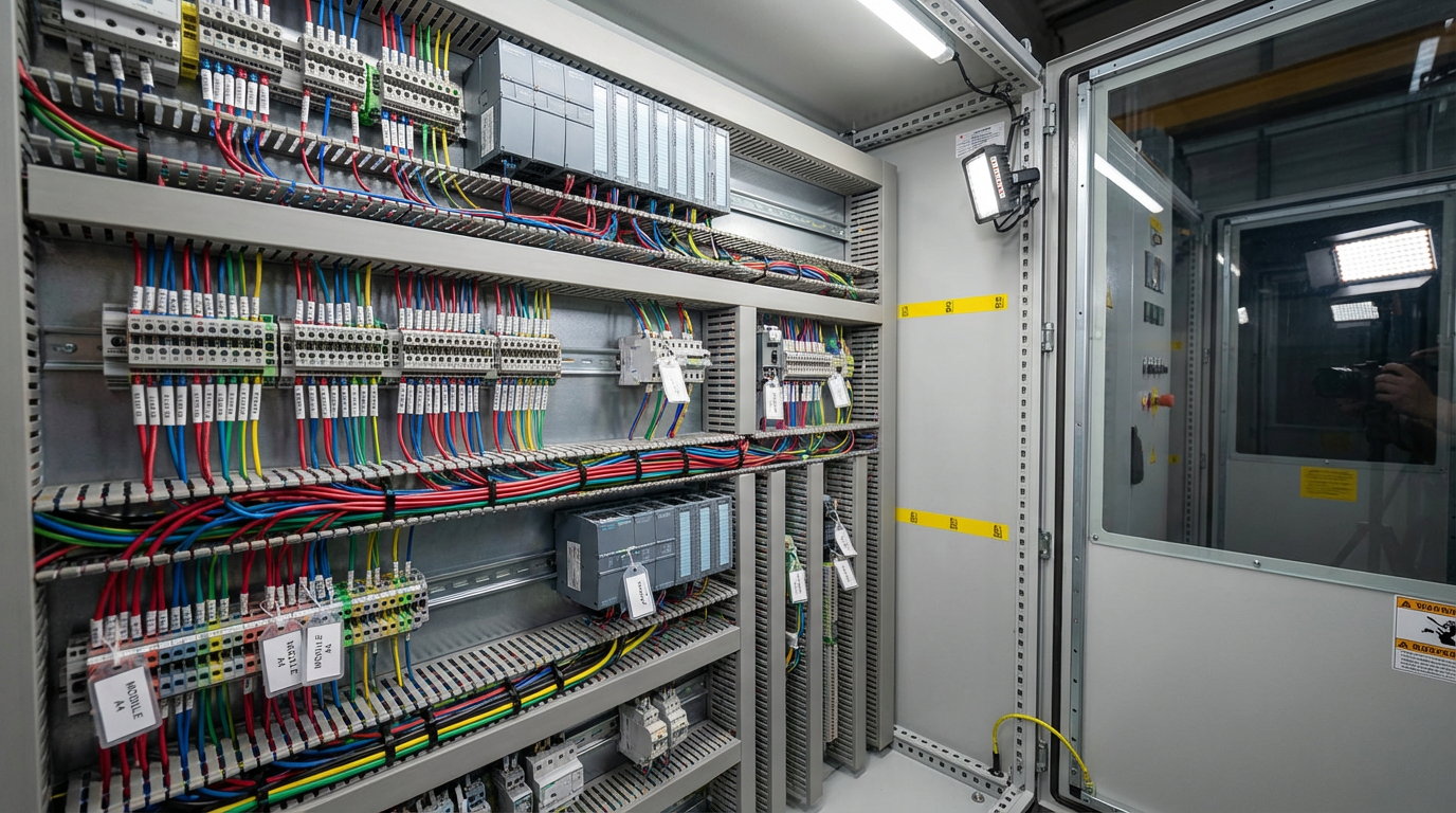
DC Input Sink/Source Configurable: Flexible Wiring Without the Headaches
Why Sink/Source Still Trips Up Good Engineers
If you work in industrial automation long enough, you eventually lose a shift to a simple wiring mistake. In my case, some of the most avoidable downtime has come from sink/source confusion on 24 VDC I/O. The logic in the PLC program was fine, the field devices were healthy, but a mismatch between sinking and sourcing circuits left inputs floating or shorted. As Oriental Motor points out in its control basics material, incorrect sink/source wiring can range from “motor does nothing” to permanent damage.
The real frustration is that these problems often surface late: during commissioning at 3:00 AM, after a retrofit, or when a technician swaps a sensor “like‑for‑like” but accidentally changes from PNP to NPN. Forum threads from AutomationDirect, Inductive Automation, and Digikey are full of teams discovering that “DC COM” was not necessarily negative, that a “universal” card was not wired the way they assumed, or that a missing wire at a contactor quietly disabled a single input mid‑production.
Configurable DC inputs that can operate as either sinking or sourcing are one of the most practical tools we have for bringing some sanity to this mess. Instead of stocking separate input modules or redesigning entire I/O groups when a device changes, a properly designed sink/source configurable input gives you wiring flexibility while preserving safety and reliability. The key is understanding what sink and source really mean in a DC circuit and how configurable inputs implement that behavior.
What Engineers Mean by Sink and Source
Several reputable training resources, including RealPars, ControlByte, and AutomationDirect’s technical library, all converge on the same basic picture. Every DC I/O circuit needs three things: a voltage source, a load, and a return. The moment you define which side of the circuit current flows out of and which side it flows into, you have defined source and sink.
A device is sourcing when current flows out of it into another device. A sourcing output typically uses a PNP transistor to switch the positive side of a 24 VDC supply toward the load. A device is sinking when it receives that current and provides a path back to the supply common.
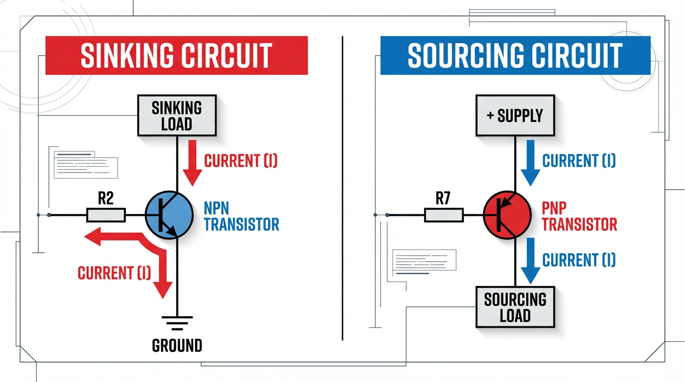
A sinking output typically uses an NPN transistor to switch the load to the negative or common side of the supply.
Oriental Motor describes it in even more visual terms. Think of a source circuit as providing a controlled path to the voltage source, and a sink circuit as “sinking” current toward ground. Their explanation emphasizes that this is a DC‑only concept; AC systems alternate polarity, so the terms do not apply in the same way.
Both RealPars and AutomationDirect stress a non‑negotiable rule: for DC transistor I/O to work correctly, a sinking device must pair with a sourcing device. You connect PNP (sourcing) sensors into sinking inputs, and NPN (sinking) sensors into sourcing inputs. Connecting source to source or sink to sink leaves current with no proper path and either prevents the input from turning on or drives it in uncontrolled ways.
To anchor the discussion, it is useful to compare sinking and sourcing behavior side by side.
| Aspect | Sinking (NPN) view | Sourcing (PNP) view |
|---|---|---|
| Current path | Current flows from supply positive, through the load, into the sinking device, to common | Current flows out of the sourcing device from supply positive, through the load, back to common |
| Transistor type | NPN transistor provides path to common (ground/return) | PNP transistor provides path to positive supply |
| PLC card type | Sinking input accepts current from a sourcing field device; sinking output pulls load to common | Sourcing input pulls load toward positive; sourcing output drives current to the load |
| Typical field device match | NPN outputs on sensors must connect to sourcing inputs | PNP outputs on sensors must connect to sinking inputs |
| Common wiring convention | Common terminal often tied to negative side of 24 VDC supply | Common terminal often tied to positive side of 24 VDC supply |
| Safety note | Input is closer to common, so a short to ground can more easily force ON or OFF depending on design | As Oriental Motor notes, certain source‑logic arrangements can be less likely to turn inputs on due to accidental leakage to ground |
RealPars emphasizes that these are not abstract textbook definitions. A PLC input or output card is built as either a sink or source module, or occasionally as a configurable combination. The field devices you hang on those points—photoelectric sensors, proximity switches, touch buttons, motor drives—often have PNP or NPN transistors built in. Matching those pieces correctly is fundamental design work, not a detail to delegate to the night‑shift electrician.
Why Sink/Source Configurable DC Inputs Matter
Traditional PLC input modules force you to pick a side at purchase time. You order a sinking module or a sourcing module, wire every common on that card accordingly, and live with that choice for the life of the panel. That approach can work when you fully control the device ecosystem and enforce a plant standard. Control.com’s guidance suggests exactly that: choose one dominant convention—commonly PNP field devices feeding sinking inputs—document it clearly, and avoid mixing NPN and PNP on the same project unless absolutely necessary.
Modern plants, however, rarely look that clean. You inherit existing machines that were built around NPN sensors. You add a new OEM skid that assumes PNP. You migrate from one drive family to another and discover that the I/O on the new drive is the opposite logic of your PLC card. In those situations, a rigid input module becomes a liability.
Sink/source configurable inputs address this by making the input electronics tolerant of either wiring style. Oriental Motor describes motor drivers whose DC inputs can be wired so that a shared input common can connect either to 24 VDC or to 0 VDC, while the same input terminals continue to function properly. The trick is inside the input circuit: optocouplers and bidirectional diodes allow the LED inside the coupler to be driven whether current arrives from the positive side or from the negative side.
The benefits in the field are very practical. A configurable input may let you:
First, reuse an existing PLC card when a machine upgrade replaces NPN proximity switches with PNP models. You move the common from one side of the supply to the other and re‑label the block, instead of swapping hardware.
Second, land both OEM skids and plant‑standard devices on the same rack by dedicating I/O groups and configuring each group appropriately. You keep wiring straightforward without ordering specialty cards for each vendor.
Third, stock fewer spares. A generic “sink/source configurable” DC input card can replace either a sinking or sourcing input module when a board fails. For maintenance teams, that simplifies inventory and shortens recovery times.
It is worth noting that AutomationDirect and RealPars both caution that even on configurable modules, all points that share a common must be wired consistently, either as all sinking or all sourcing. Configurable does not mean you can wire each individual point arbitrarily; the grouping rules still apply.
Inside a Configurable DC Input
You do not need to reverse‑engineer every card on your control panel, but a conceptual view of configurable DC inputs helps you wire them with more confidence.
A basic DC input circuit, as described by Oriental Motor and AutomationDirect, looks like this: a resistor and LED inside a photocoupler form the “load” side of the input. When enough current flows through that LED, a transistor on the logic side turns on, and the PLC or drive sees the input as “true.”
A pure sinking input ties one side of the LED to the module’s internal common and brings field current from the positive side of the supply through the external field device, into the LED, and down to common. A pure sourcing input does the opposite: the LED is tied to the positive internal rail, and field current flows from the LED through the external device to common.
Products that accept both sink and source wiring, such as the drivers described by Oriental Motor, typically add two extra ingredients. Bidirectional diodes around the LED allow current to flow in either direction through the coupler, and the internal reference (“input common”) is brought out to a separate terminal. If you tie that common terminal to 24 VDC, the external device and input behave as a sinking combination.
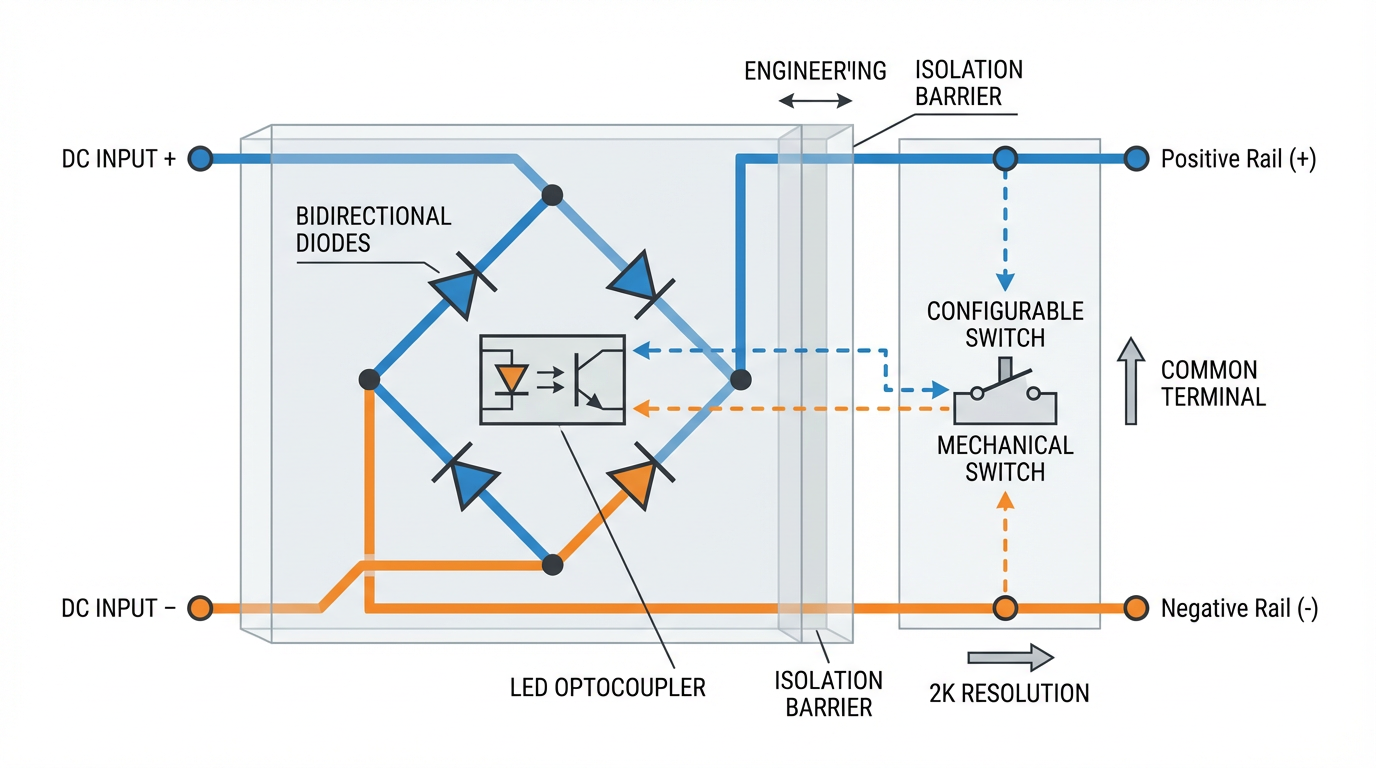
If you tie it to 0 VDC, they behave as a sourcing combination.
From the field technician’s point of view, the wiring decision looks deceptively simple: choose whether IN‑COM or DC COM goes to positive or to negative. Underneath that choice is the entire definition of sink vs source. This is where the mnemonic from Oriental Motor is helpful: if the input common is wired to the supply positive, the input circuits provide paths to ground and therefore behave as sinking inputs. If the input common is wired to the supply negative, the input circuits provide paths to voltage and therefore behave as sourcing inputs.
Because the optocoupler is an electrical isolation barrier, this topology also tolerates modest mistakes better than a simple transistor input. Photo‑coupled inputs, as Oriental Motor notes, are more forgiving of wiring damage and reduce the risk that a short will propagate deep into the logic electronics.
Wiring Scenarios You Will Actually See
Theory is nice, but most engineers need to see how configurable inputs save time in the specific situations that actually show up in projects. The following scenarios are distilled from real‑world patterns discussed by AutomationDirect, RealPars, ControlByte, Digikey’s application notes, and community forums.
Scenario 1: Migrating from NPN to PNP Sensors
Assume you inherited a machine where every photoelectric sensor is NPN: each sensor’s black wire pulls an input to the negative side of the 24 VDC supply when the object is detected. The matching PLC card is a sourcing input module, with its common tied to 24 VDC and each input wired down to the sensors. The machine runs, but replacement NPN sensors are getting harder to source, and a plant standard mandates PNP going forward.
If your PLC inputs are sink/source configurable rather than fixed sourcing, the migration path is straightforward. You change the input card’s common wiring so that the common terminal goes to 0 VDC instead of 24 VDC. The card now behaves as a sinking input module. New PNP sensors drive current from 24 VDC into the card inputs and down to the common at 0 VDC. The individual input terminals on the PLC do not have to be rewired; the change happens at the common node and at the sensor side.
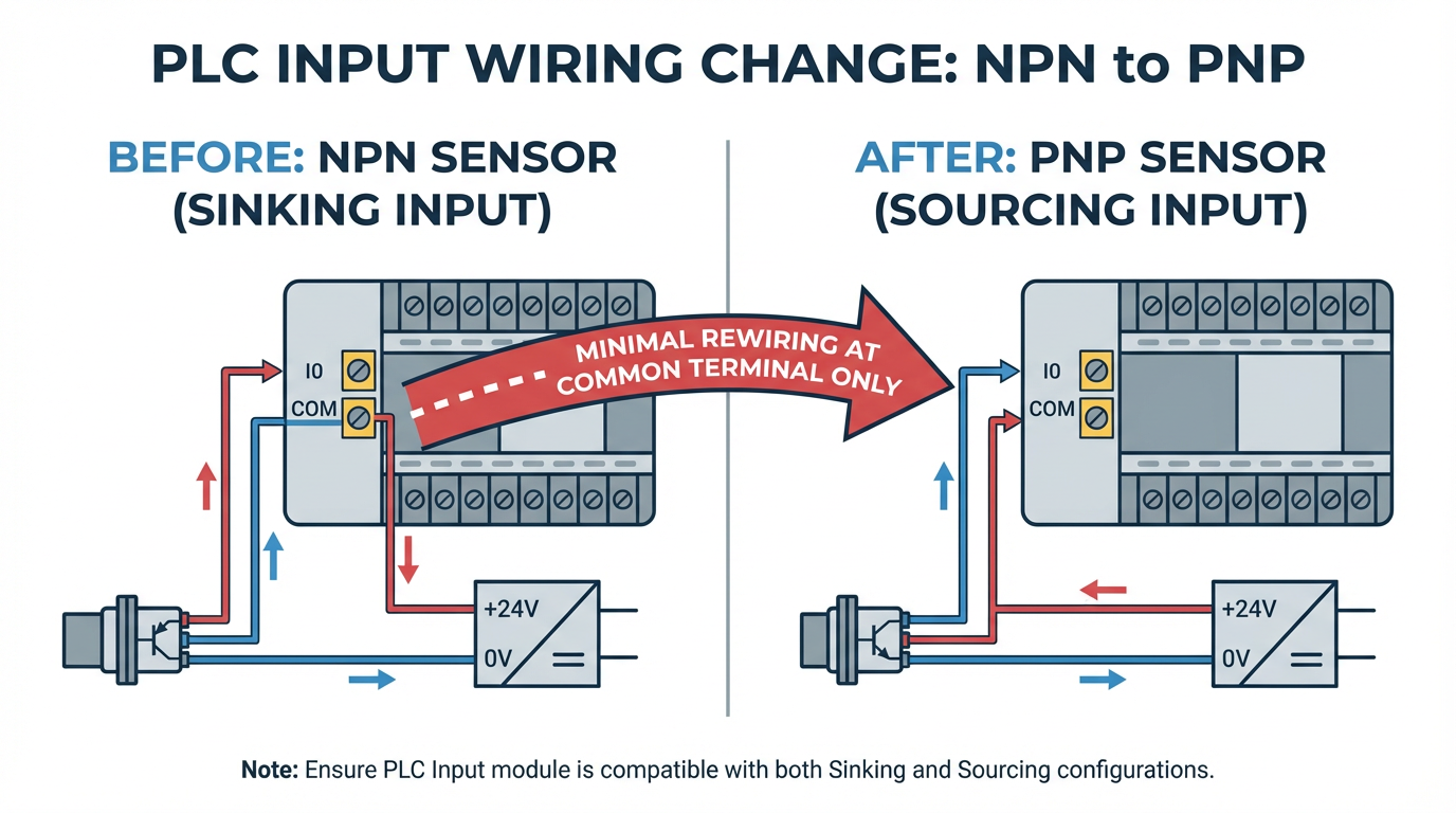
This approach mirrors the flexibility described by Oriental Motor for their motor drivers, where a single IN‑COM terminal can be wired to either side of the 24 VDC supply. It also honors AutomationDirect’s requirement that all points sharing that common must be wired consistently. You still have a “block” of inputs that are all sinking or all sourcing, but you did not have to replace the hardware to change which.
Scenario 2: Integrating Mixed OEM Equipment
Modern control panels often house a mix of PLC I/O, servo drives, brushless motor drivers, and safety devices from different manufacturers. The Digikey example of a touch button that offers both sinking and sourcing outputs illustrates this perfectly. One wire from the button behaves as a sinking output; another behaves as a sourcing output. The device is extremely flexible, but only if the rest of your circuit can accept either behavior.
A sink/source configurable input bank gives you options. You can dedicate one input block to OEM equipment that only offers NPN outputs by wiring its common to 24 VDC (making those PLC points sourcing). Another input block can be wired with common at 0 VDC to accept your plant’s standard PNP sensors. In both cases the same model of PLC input card is used, and field wiring is routed cleanly in separate duct or even separate sections of the panel, following cable management best practices from Bud Griffin & Associates and Simcona.
Because the commons, cable color codes, and documentation differ between the sections, you greatly reduce the risk that a future technician lands a PNP sensor on the NPN block or vice versa. The I/O hardware is flexible, but the panel layout and documentation enforce discipline.
Scenario 3: Troubleshooting a Dead Input in a “Rats Nest” Panel
Community threads hosted by AutomationDirect and Inductive Automation are full of stories about plants where a single digital input stopped working and no one knew why. In one case, a technician assumed that “DC COM” on an input module was automatically negative. In reality, that terminal was simply the shared common reference and could be tied to either side of the supply. A missing wire at a contactor left one input without a return path, even though a quick jumper test made the PLC point light up.
With configurable inputs, this kind of fault is easier to isolate if you follow a structured process. First, confirm the module will respond by directly jumpering 24 VDC to the suspect input or by providing a controlled path to common, depending on whether the block is configured as sinking or sourcing. Second, trace the field wiring back using the electrical prints, as recommended in the Inductive Automation discussion. If the jumper test works, the card is likely healthy and the problem lies in field wiring, missing commons, or mis‑landed conductors.
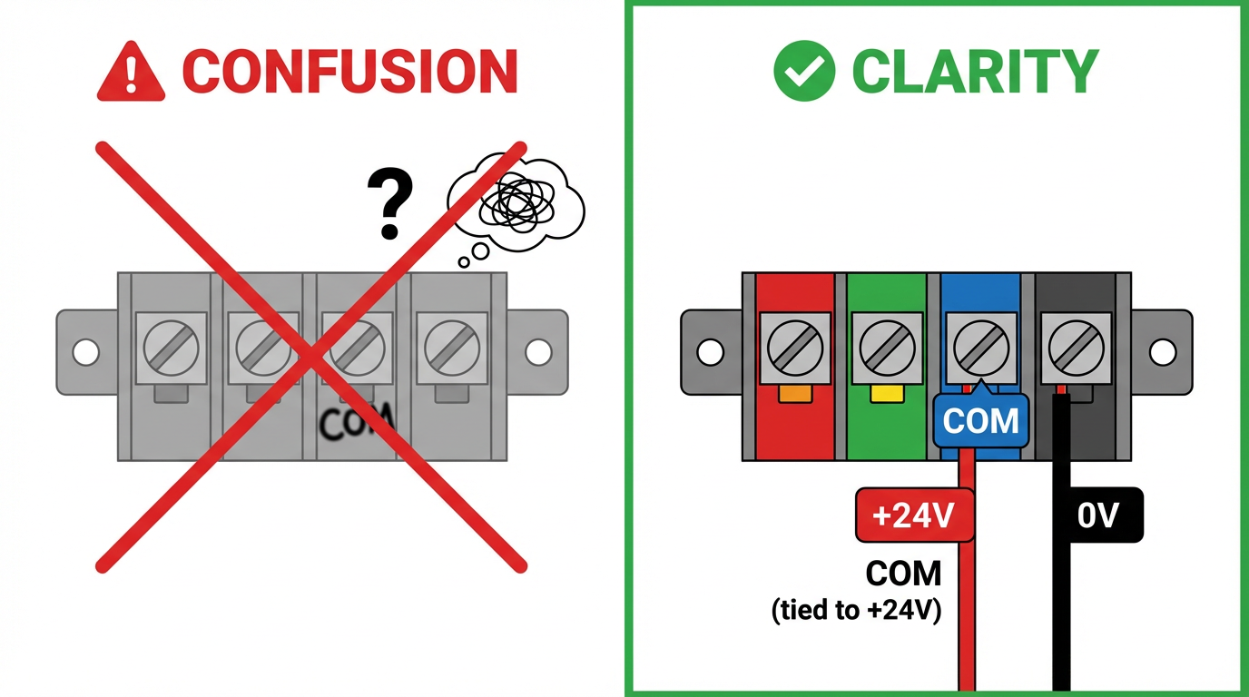
Because configurable modules make the concept of “common” explicit, they also encourage better labeling. Instead of a vague “COM,” you mark the terminal as “COM (tied to +24 V)” or “COM (tied to 0 V).” That labeling alone would have saved several hours in the forum example where the assumption that COM meant negative led troubleshooting astray.
Panel Design, Cabling, and Documentation
Flexible I/O does not live in a vacuum; it lives in a control panel full of power supplies, drives, and communication hardware. Articles from Simcona on panel layout and Bud Griffin & Associates on cable management both stress that good physical organization is just as important as having the right schematics.
For sink/source configurable inputs this translates into a few concrete practices. Keep DC I/O away from high‑power “noise creators” like VFDs and large DC drives, echoing the noise‑isolation advice from Industrial Automation Co and Keysight. Use vertical and horizontal cable managers so that mixed sensor types can be grouped by common and voltage level, not just by which side of the panel they happen to be closest to. Ensure that shared commons for each I/O block are routed cleanly and accessibly; they are not afterthought wires but critical parts of the current path.
Clear labeling and documentation matter just as much. Bud Griffin & Associates recommend maintaining blueprints, diagrams, and records of cable routes, and that advice is especially relevant when an input block’s behavior can change with a simple re‑landing of the common. On the drawings, show the entire loop: supply positive, through the field device, into the input terminal, through the input circuit, out the common, and back to the supply return.
RealPars and AutomationDirect both argue that you should treat the choice of sink vs source as a deliberate design parameter during the panel design phase, not as a wiring detail to be improvised on site. A configurable module gives you more options at design time; it does not absolve you from deciding which option is correct for each block and documenting that choice.
For larger facilities, a data center style mentality is helpful. Bud Griffin & Associates advocate using Data Center Infrastructure Management tools to track rack, cabling, and airflow decisions in server rooms. A similar discipline in industrial panels—using CAD with layer assignments for sensor types, commons, and voltage levels—makes future modifications to sink/source configuration less risky.
Safety, Noise, and Measurement Around DC Inputs
While sink/source configuration is often discussed purely in logical terms, safety and signal integrity should sit at the center of your decisions. RealPars explicitly warns never to power DC transistor circuits from AC supplies, because the alternating polarity violates the assumptions of PNP and NPN devices and leads to faults. That may sound obvious, but in the field it is surprisingly easy for someone to grab the “nearest 24 volt” terminals without checking whether the source is AC or DC.
Several sources, including Oriental Motor and RealPars, also highlight safety differences between wiring styles. In some source‑logic arrangements, an input circuit is not directly tied to the positive side of the supply, so a leakage path or short to ground is less likely to turn the input on inadvertently. While the right choice depends on the application, it is important to evaluate how each scheme behaves when insulation fails, cables chafe, or moisture creates partial shorts.
Noise and measurement accuracy are another often overlooked dimension. Keysight’s guidance on DC voltage measurement errors shows how radio‑frequency interference, magnetic fields, loading errors, and power‑line noise can all corrupt readings. In a control panel, long sensor runs can behave like antennas, picking up emissions from nearby VFDs or switching DC‑DC converters. The DC‑DC converter articles from eBOM and Transfar Electronics further explain how high‑efficiency switching regulators inherently generate electromagnetic noise, which must be managed through layout, filtering, and proper component placement.
The practical takeaway for DC inputs is straightforward. Keep sensor cabling away from high‑frequency noise sources. Where that is impossible, use shielded cable and land the shield correctly. Treat the I/O power supply as part of the signal chain: select converters with appropriate ripple and noise performance, and follow the EMI recommendations from the power‑electronics community, such as using ferrite beads and decoupling capacitors to protect sensitive analog sub‑circuits that share the same supply.
When you troubleshoot a suspect input, be aware that your own instruments can lie to you if you neglect these factors. Keysight notes that unshielded leads moving in a magnetic field can generate millivolt‑level errors, and that insufficient input resistance on a meter can load a high‑impedance source. Digital PLC inputs typically represent robust loads compared with a DMM, but if you are chasing a marginal signal, these details matter. Verify that your meter’s integration time and noise filtering are set appropriately when measuring signals in electrically noisy environments.
Common Pitfalls with Configurable Sink/Source Inputs
Flexible hardware can either eliminate or encourage mistakes, depending on how you use it. The recurring issues I see in plants match the patterns described by RealPars, AutomationDirect, ControlByte, and forum case studies.
One chronic problem is assuming that “COM” printed on a module always means negative. The AutomationDirect community and Inductive Automation forum both contain examples where this assumption led technicians astray. On a configurable DC input, COM is the reference point for that group of channels. Whether it is at 24 VDC or 0 VDC depends entirely on how the panel is wired. If the common is landed incorrectly or a jumper is missing, none of the inputs in that group will behave as expected.
Another pitfall is mixing PNP and NPN sensors on the same common group. RealPars recommends wiring all I/O points that share a common as either all sourcing or all sinking, which makes it easier to share a common conductor across multiple devices and reduces terminal count. AutomationDirect goes further and warns that on so‑called sink/source modules, the configuration is per common group, not per point. Trying to get clever and alternate between PNP and NPN devices on adjacent channels of the same common is a recipe for hidden faults.
A subtle but dangerous mistake surfaces when someone reconfigures a card’s common from 24 VDC to 0 VDC (or the reverse) to accept a new device, but fails to audit every field device on that group. A card that once happily accepted PNP sensors into sinking inputs may now be wired as sourcing, rendering previously healthy PNP sensors inoperative or even stressed. Any time you change a group common, you must treat it as a design change, not just a wiring tweak.
Environmental factors also play a quiet role. In the wastewater plant example summarized from a LinkedIn case study, a PLC racked up random STOP faults until someone discovered corrosion on the backplane contacts. The CPU and I/O modules were fine; the rack was not. Corrosive vapors, moisture, and temperature swing all degrade insulation and contact quality over time. A marginal connection on a configurable input common can produce intermittent behavior that masquerades as a transistor failure or logic bug. Regular inspection of racks, commons, and terminal blocks is as important as verifying that the right PNP or NPN symbol appears on the drawings.
Finally, do not underestimate the human factor. Industrial Automation Co’s discussion of DC drive failures highlights how incorrect or improvised wiring remains a leading cause of equipment damage. Cable management articles from Bud Griffin & Associates and Simcona show how “rats nest” wiring makes it far harder to spot missing commons, mis‑landed conductors, or improvised jumpers. Good harnessing, clear separation of power and control wiring, and disciplined labeling make sink/source configuration mistakes much easier to prevent and diagnose.
FAQ
How do I tell if a PLC input card is currently wired as sinking or sourcing?
Start with the documentation for the module, since reputable vendors clearly show whether the electronics inside each common group behave as sinking, sourcing, or configurable. Then examine how the common terminals are wired in the panel. If the common for a group of inputs is tied to the positive side of the 24 VDC supply, that group is behaving as sinking inputs. If the common is tied to the negative or return side, that group is behaving as sourcing inputs. A quick controlled jumper test, as suggested in AutomationDirect and Inductive Automation community discussions, can confirm behavior: temporarily apply 24 VDC to an input or provide a path to common and verify the PLC sees the point as ON.
Does sink/source configurable mean I can wire every channel differently?
On almost all practical hardware, the answer is no. AutomationDirect’s explanation of sink/source modules makes it clear that configuration is shared across the channels that share a common. That group must be wired consistently as either all sinking or all sourcing. If you need both behaviors, you typically dedicate one common group to PNP devices and another to NPN devices, or use different cards. The flexibility lies in how you allocate groups, not in wiring each point arbitrarily.
Is one logic inherently safer: sinking or sourcing?
RealPars and Oriental Motor both suggest that safety depends more on the specific wiring and the fault scenarios you expect than on the label. Some source‑logic arrangements can be less likely to turn an input on due to leakage or accidental shorts to ground, while certain sink‑logic arrangements may give clearer fault behavior if a wire opens. The practical approach is to analyze how your circuit behaves when cables short to adjacent conductors, to the panel, or to earth, and to apply applicable safety standards and design guides from vendors and organizations such as NFPA and UL. Sink/source configurable inputs give you the freedom to pick the style that best matches your safety and diagnostic strategy, rather than forcing you into one convention everywhere.
In industrial automation, flexible DC inputs are not about being clever; they are about making the next wiring change safer, faster, and easier to understand. When you pair sound sink/source fundamentals with thoughtful panel design, disciplined cable management, and clear documentation, configurable inputs become a powerful way to reduce risk and keep your systems running when it matters most.

References
- https://blog.orientalmotor.com/what-is-the-difference-between-sink-and-source-logic
- https://library.automationdirect.com/3-wire-sinking-sourcing-devices-plc-input-modules/
- https://bgasales.com/cable-management-best-practices/
- https://www.ebom.com/dc-to-dc-converters-common-types-issues-and-challenges/
- https://www.industrialcommerciallighting.com/blog/optimizing-the-placement-of-led-drivers-for-maximum-efficiency.html?srsltid=AfmBOooJHuop1nZgBRyNB_e5HsrGJy6F-7q9TuQ_UTNwlPWCrDn6ZRFe
- https://www.instructables.com/Electronic-Circuit-Mistakes-Goofs-and-Surprises/
- https://docs.keysight.com/kkbopen/comprehensive-look-at-sources-of-error-in-dc-voltage-measurements-582630458.html
- https://www.linkedin.com/posts/instrumentation-and-control-engineering_plc-automation-sinkvssource-activity-7335515700460965889-X86q
- https://www.realpars.com/blog/sinking-and-sourcing-connection
- https://simcona.com/blog/control-panel-layout-design
Keep your system in play!
Top Media Coverage
Categories


Related articles Browse All
-
 amikong NewsSchneider Electric HMIGTO5310: A Powerful Touchscreen Panel for Industrial Automation2025-08-11 16:24:25Overview of the Schneider Electric HMIGTO5310 The Schneider Electric HMIGTO5310 is a high-performance Magelis GTO touchscreen panel designed for industrial automation and infrastructure applications. With a 10.4" TFT LCD display and 640 x 480 VGA resolution, this HMI delivers crisp, clear visu...
 -
 BlogImplementing Vision Systems for Industrial Robots: Enhancing Precision and Automation2025-08-12 11:26:54Industrial robots gain powerful new abilities through vision systems. These systems give robots the sense of sight, so they can understand and react to what is around them. So, robots can perform complex tasks with greater accuracy and flexibility. Automation in manufacturing reaches a new level of ...
 -
 BlogOptimizing PM Schedules Data-Driven Approaches to Preventative Maintenance2025-08-21 18:08:33Moving away from fixed maintenance schedules is a significant operational shift. Companies now use data to guide their maintenance efforts. This change leads to greater efficiency and equipment reliability. The goal is to perform the right task at the right time, based on real information, not just ...


- Q&A
- Policies How to order Part status information Shipping Method Return Policy Warranty Policy Payment Terms
- Asset Recovery
- We Buy Your Equipment. Industry Cases Amikong News Technical Resources Why choose us
- ADDRESS
-
 32D UNITS,GUOMAO BUILDING,NO 388 HUBIN SOUTH ROAD,SIMING DISTRICT,XIAMEN
Leave Your Comment