
-
Please try to be as accurate as possible with your search.
-
We can quote you on 1000s of specialist parts, even if they are not listed on our website.
-
We can't find any results for “”.
Designing Control Modules with Conformal Coating to Meet a Class 3C Protection Standard
When you install a control module in a wet, dirty, chemically aggressive plant and expect it to run for a decade, you are no longer buying a commodity PCB in a box. You are buying an engineered protection system. In my experience as a systems integrator, the projects that survive those environments share one common trait: they treat conformal coating and high protection classes such as “3C” as hard engineering requirements, not marketing labels.
The research from Dymax, HZO, Altium, Techspray, NASA workmanship standards, and IPC guidance all converge on the same conclusion. A correctly selected and correctly applied conformal coating turns a vulnerable control board into a reliable control module, even in harsh service. The challenge is getting the details right: chemistry, design, process, and verification.
In this article I will walk through how to design and specify a control module with conformal coating suitable for a high chemical and moisture exposure class often referred to as “3C”. For this discussion, I will use “3C-level” as shorthand for environments with condensing humidity, corrosive contaminants, and long duty cycles, while relying strictly on the behaviors and data described in the research notes.
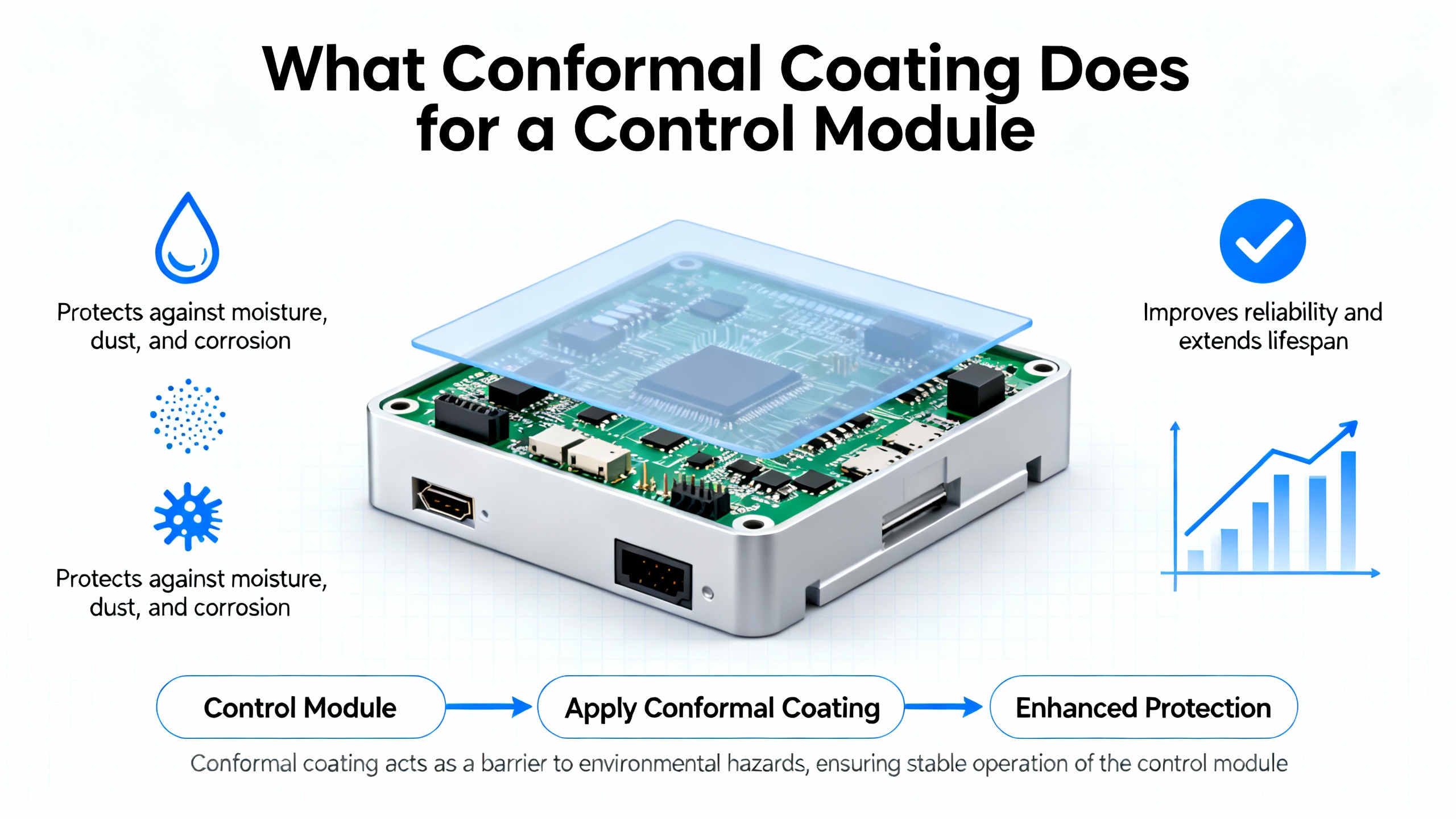
What Conformal Coating Does for a Control Module
Conformal coating is a thin polymer film applied to fully assembled circuit boards. Dymax and several other sources describe typical dry film thicknesses around 25–150 micrometers, which is roughly 1–6 mil, with IPC-CC-830C recommending about 1–3 mil as a sweet spot. That film conforms to components and traces instead of forming a rigid block like potting.
Across sources such as Dymax, Altium, Techspray, TT Electronics, and others, the main functions are consistent. The coating creates a dielectric barrier that increases surface insulation resistance, reducing leakage currents, crosstalk, and arcing between closely spaced conductors. It blocks moisture, condensation, dust, salts, and aggressive chemicals from reaching copper traces and component leads, which significantly slows corrosion and dendrite growth. It provides some mechanical damping against vibration and shock, especially for flexible chemistries like silicone. It supports miniaturization by allowing tighter spacing between conductors and reducing the need for bulky environmental housings. Some coatings, as Dymax notes, can even obscure markings and component details, offering a degree of protection for proprietary designs.
The key point for control modules is that a conformal coating is not there for cosmetics. It is an electrical insulation system, a corrosion barrier, and a mechanical stabilizer in one. In automotive ECUs, for example, HZO data shows that unprotected boards fail very quickly in highly accelerated temperature and humidity tests, while coated boards can survive exposures at about 266°F and 90% relative humidity without abnormal current spikes. Industrial control modules see similar stress patterns, even if the environment is a wastewater plant instead of an engine bay.
How to Think About a “3C-Level” Protection Requirement
Different standards and vendors use different labels for environmental classes, and the research notes do not define “3C” formally. What they do describe in detail is what “harsh environment” really means for electronics.
Across Dymax, Qual-Pro, Techspray, and TT Electronics, harsh service is characterized by continuous or frequent exposure to high humidity and condensation, salt spray and corrosive chemicals, airborne pollution and dust, wide temperature swings, and sustained vibration or mechanical shock. NASA’s workmanship standard for polymeric applications on electronic assemblies (NASA-STD-8739.1) also emphasizes that coatings must provide environmental protection and vibration resistance, not just pass a lab thickness check.
So for practical purposes, when I see a project specification calling for something like “3C-class control modules,” I translate that into the following engineering expectations, grounded in the research:
I expect the coating to maintain adhesion and insulation under long-term humidity, salt, and chemical exposure, not just short splash events. I expect coverage on edges, corners, and around fine-pitch parts to be robust, because Gen3 Systems work shows that thin or missing edge coverage is a major driver of failures under condensation and Surface Insulation Resistance (SIR) testing. I expect the coating chemistry to tolerate the full temperature profile of the module. Silicone coatings described by Altium and Techspray handle continuous operation up to about 400°F. Parylene F, in the HZO data, is comfortable from roughly −67°F to about 392°F. Anything calling itself high protection class should be in that league. I expect the process to follow recognized workmanship practices such as NASA-STD-8739.1 and IPC-CC-830C, with real cleanliness control, not a quick solvent wipe at the end of the line.
In other words, a “3C-level” control module is not just any coated board. It is a combination of the right coating chemistry, the right mechanical and PCB design, and a disciplined process that delivers reliable coverage where it matters most.
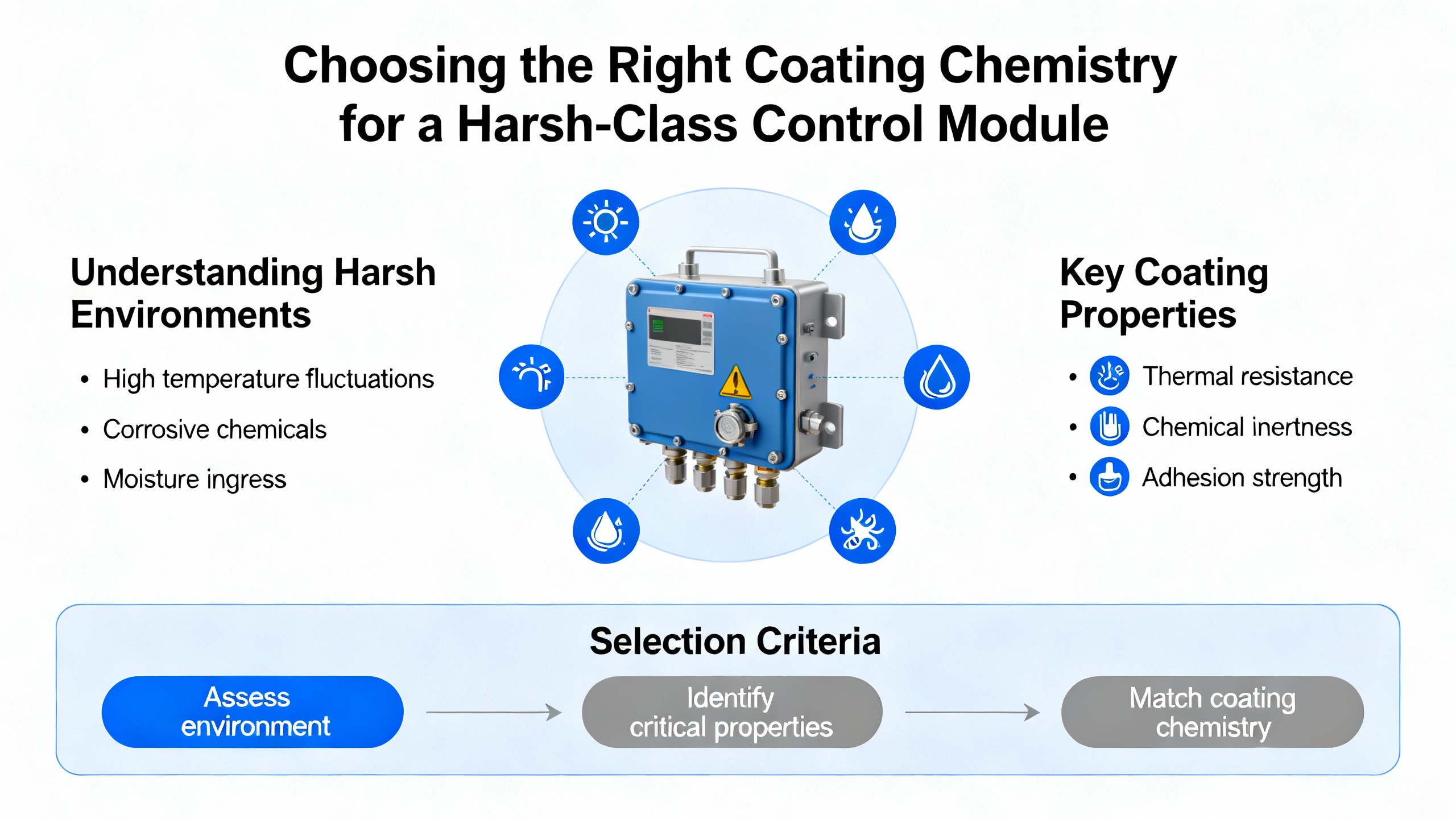
Choosing the Right Coating Chemistry for a Harsh-Class Control Module
The research set covers the major coating families very consistently: acrylic, silicone, polyurethane or urethane, epoxy, Parylene, and newer thin-film fluorocarbon “nano” coatings. They are all conformal coatings, but they are not interchangeable. For a high-chemical, high-humidity class, some are clear front-runners, and others are better suited to milder service or reworkable designs.
The table below summarizes the main types, based on data from Altium, Techspray, Dymax, UnitCircuits, Qual-Pro, TT Electronics, and HZO.
| Coating type | Strengths from the research | Main limitations from the research | Suitability for harsh “3C-level” environments |
|---|---|---|---|
| Acrylic (AR) | Low cost, easy to apply and remove with common solvents; good long-term moisture and UV resistance; fast drying; supports rework and repair. | Poor solvent and chemical resistance; relatively narrow useful temperature range; can be softened or stripped by many solvents; limited abrasion resistance. | Adequate for moisture and basic outdoor exposure when chemical attack is limited. Marginal where aggressive solvents, fuels, or industrial chemicals are expected. Useful for indoor control modules or where reworkability is a priority. |
| Silicone (SR) | Remains elastic after cure; excellent resistance to moisture and corrosion; tolerates high operating temperatures near 400°F; good for vibration damping and thermal cycling; widely used in high-moisture, high-temperature applications. | Higher thermal resistance can impede heat dissipation; relatively poor abrasion resistance; more difficult to remove for rework compared with acrylic. | Strong choice for control modules near hot machinery, in humid or condensing environments, or subject to vibration. Very appropriate for harsh “3C-level” duty where temperature swings and moisture dominate. |
| Polyurethane / Urethane (UR) | Tough film with strong resistance to moisture, solvents, and chemicals; good abrasion resistance; widely used where fuel vapors and aggressive chemicals are present; cited in aerospace and harsh industrial settings. | Difficult and time-consuming to remove; often requires harsh stripping chemistries; cure can demand heat or UV and is better suited to production than prototyping. | Well aligned with chemically aggressive environments where rework is rare and long-term solvent resistance is more important than repairability. Good fit for chemically loaded “3C-level” plants and immersion-cooled electronics. |
| Epoxy (ER) | Very hard, non-permeable coating with excellent abrasion and chemical resistance; strong moisture barrier; often used in potting where complete encapsulation is required. | Two-part systems with short pot life and complex mixing; cures to a rigid, inflexible film; highly difficult to rework; can induce mechanical stress and cracking where boards flex or components move. | Suitable for extremely harsh, mechanically static electronics. For control modules, epoxy is often too rigid and too hard to service; better reserved for very high-risk assemblies where repair is not expected. |
| Parylene (XY types) | Vapor-deposited, pinhole-free, ultra-uniform 3D coverage including edges and corners; outstanding moisture and chemical barrier; very high dielectric strength; minimal added weight; operates over wide temperature ranges. HZO data shows Parylene C and F matching or exceeding IPC-CC-830C criteria at about half the thickness of traditional liquids. | Requires specialized Chemical Vapor Deposition equipment; very difficult to remove; higher process cost; application typically outsourced or centralized. | Arguably the best available protection for harsh 3D geometries and dense modules. Ideal for safety-critical or inaccessible control modules where downtime is extremely costly. Very strong match for a high protection class, provided the business case supports the process cost. |
| Thin-film “nano” fluorocarbon | Extremely thin hydrophobic layers; provide limited protection against brief water exposure; easy to apply via spray or dip; minimal effect on dimensions. | Do not provide the robust mechanical and chemical protection of traditional coatings; not suited to severe chemicals or long-term immersion; limited barrier properties. | Useful for low-duty or consumer applications. Insufficient on their own for the levels of moisture and chemical attack implied by a “3C-level” industrial environment. |
In practice, when I am specifying a control module for harsh duty, I tend to separate use cases this way, based strictly on the behaviors described in the research:
If the dominant threats are condensation, humidity, and vibration, and the modules run hot, silicone coatings are often my first choice. Altium and Techspray both emphasize their broad temperature range and flexibility, which matches elevated ambient temperatures and thermal cycling near heavy drives and motors. If the environment is chemically aggressive, such as exposure to solvents, fuels, or strong cleaners, I look very seriously at polyurethane. Techspray and UnitCircuits highlight its superior solvent and chemical resistance, which is exactly what you need in chemical process modules or immersion-cooled servers. Where the control module is safety-critical, extremely dense, or deeply buried in equipment, HZO’s Parylene data is compelling. Its edge and corner coverage, very low water vapor transmission, and success in harsh accelerated tests argue strongly for Parylene on, for example, high-end motion controllers or drive modules in corrosive atmospheres.
Acrylic and epoxy still have roles. Acrylic is an honest, low-cost workhorse for milder service and for modules you expect to rework regularly. Epoxy is the right answer if you are really building something closer to a sealed brick than a maintainable control card.
Designing the Control Module for Coating From Day One
Every coating vendor will tell you that you cannot fix a bad board layout with process tweaks, and the Electrolube and Altium design guidance in the notes backs that up.
Board design constraints strongly determine what coating methods are even feasible and what coverage you can achieve inside a reasonable cycle time. Electrolube recommends clearly indicating must-coat, must-not-coat, and neutral areas on drawings. Grouping uncoated connectors and components along one edge simplifies masking and may even enable dip coating. Placing tall components that must be coated right next to connectors or keep-out zones creates wicking, voids, splashing, and shadowing. For a control module, that often means putting pluggable field terminals along one edge with a clear layout zone behind them, and keeping high-rel components that must be coated away from connector bases.
Low-standoff parts such as BGAs and chip-scale packages pose a special challenge. Electrolube notes that coating can wick under these bodies and down microvias to the opposite side, potentially causing unintended coating in keep-out regions or affecting test points. Mitigation options include tenting or filling vias, or using underfill where coating presence is unavoidable but mechanical support is helpful.
Edge coating is usually low value for routed edges, because the glass and resin smear naturally seal inner layers and designers keep traces away from the board perimeter. But when panels are separated by scoring, punching, or shearing, edges may be open. In a chemically aggressive environment, you should make an explicit decision on whether edge sealing is necessary rather than assuming the router did it for you.
On thickness, MG Chemicals points to IPC-CC-830C’s recommendation of roughly 1–3 mil dry film as a good target. Their guidance is very clear that thicker is not automatically better. Excess thickness yields stress, cracking, and trapped solvents without proportional increases in protection. Typical individual liquid passes give about 0.8–1.2 mil dry; UV systems can reach higher thickness per pass. For a high-class control module, I usually specify thickness in mil, tie it explicitly to the chemistry, and insist on process coupons plus in-situ cross-sections on early builds to confirm that critical leads and corners are actually receiving the intended coverage.
Finally, it is worth treating the conformal coating as part of the electrical design in your CAD tool. Altium’s documentation, for instance, describes a dedicated conformal coating “layer” that you can define and pass to manufacturing. That allows you and your module supplier to reason about coverage, masking, and test access early, instead of negotiating tape masks after the enclosure design is frozen.
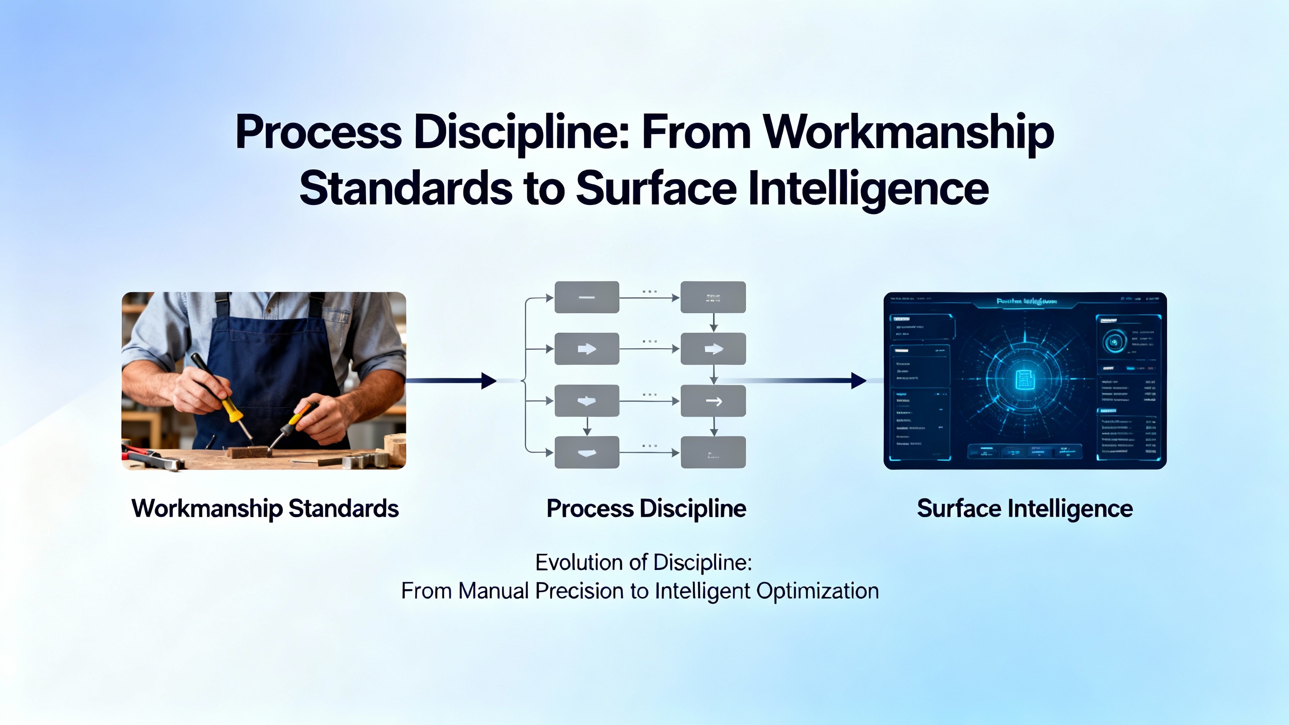
Process Discipline: From Workmanship Standards to Surface Intelligence
A well-chosen coating on a poorly prepared surface is expensive theater. NASA-STD-8739.1 emphasizes material qualification, surface preparation, environmental control, and operator training for polymeric applications, and the Brighton Science article on surface cleanliness shows exactly why.
Traditional “is the board clean?” checks like ROSE testing only measure soluble ionic contamination. Brighton Science stresses that adhesion failures such as blistering, de-wetting, delamination, and “fish eyes” are often driven by organic contamination and low surface energy, especially on polymeric laminates and plastics. Most board materials and device housings are naturally low-energy surfaces that do not want to bond to coatings. To make them “eager to bond,” you need proper cleaning plus, in many cases, energetic surface treatment such as plasma, corona, or flame.
The Brighton Science concept of Surface Intelligence is essentially closed-loop control for adhesion. Instead of assuming a cleaning recipe is working, you measure the water contact angle or related surface properties in real time at critical points. If contamination raises the contact angle beyond your acceptance band, you adjust or stop the line. Their BConnect system is one realization of that idea, but the underlying principle is universal and very consistent with NASA-STD-8739.1: you cannot control what you do not measure.
Gen3 Systems adds another layer on top: not just cleanliness, but how the coating behaves on difficult geometries. They highlight edge-coverage problems as an increasingly common reliability risk. During application and cure, surface tension and gravity tend to pull liquid coatings away from sharp corners and edges. The result is thin or missing coverage exactly where moisture and corrosion like to attack, and where dielectric strength is already compromised by geometry. Gen3 recommends careful process control, correct thickness targets, proper curing, and, importantly, SIR and condensation testing to expose these weaknesses.
In practice, on a high-class control module, I expect to see the following process elements in place, all of which are reinforced across NASA, Gen3, Techspray, MG Chemicals, and Brighton Science:
Thorough cleaning of PCB assemblies to remove flux residues, oils, and particulates, using validated chemistry and equipment rather than ad-hoc wiping. Controlled application methods with defined parameters for spray pattern, dip speed, or selective-coating paths. Thickness targets tied to the coating’s data sheet and IPC-CC-830C guidance, verified on coupons and cross-sections. Curing profiles (time and temperature) matched to the chemistry, with enough margin to ensure complete cure without damaging components. Surface cleanliness checks that go beyond visual inspection, using at least representative tests and, ideally, in-line measurement of surface energy or equivalent metrics.
Without that discipline, the label on the module does not matter; you will not get true “3C-level” behavior.
Verifying That the Module Really Delivers Harsh-Class Protection
Specification and process are necessary, but not sufficient. For harsh environments, you must see objective evidence that the control module will actually survive.
The research notes describe several relevant test approaches. SIR testing, mentioned by Gen3 Systems, measures leakage currents across test patterns on the coated board under bias in high humidity or condensation conditions. Poor edge coverage, contamination, or coating defects show up as SIR drops and electrochemical migration. Condensation testing, also discussed by Gen3, is particularly revealing. Instead of just high humidity, you deliberately create a uniform thin water layer on the board. This water penetrates microscopic gaps, especially at edges and sharp features, and quickly exposes weaknesses that might take months or years to appear in the field.
HZO’s automotive work demonstrates another style of verification: Highly Accelerated Temperature and Humidity Stress Tests (HAST) at about 266°F and 90% relative humidity, with boards under bias. Their Parylene-coated assemblies remained electrically stable, with no current spikes above 0.5 A. For a harsh-class control module, you might not run full HAST on every design, but you should be pushing early samples through meaningful combinations of elevated temperature, humidity or condensation, and bias.
On top of these environment-heavy tests, IPC-CC-830C and NASA-STD-8739.1 both assume you will verify adhesion, coverage, and absence of defects such as cracking, blushing, de-wetting, and delamination. Cross-hatch adhesion tests, cross-section microscopy, and fluorescent inspection (for coatings with tracers) are all routine methods cited in the research from MG Chemicals, Techspray, and Incure.
The most reliable control modules I have deployed in harsh plants all had one thing in common. Before anyone printed “high protection class” on the label, we had seen the coating survive a realistic abuse program in the lab.
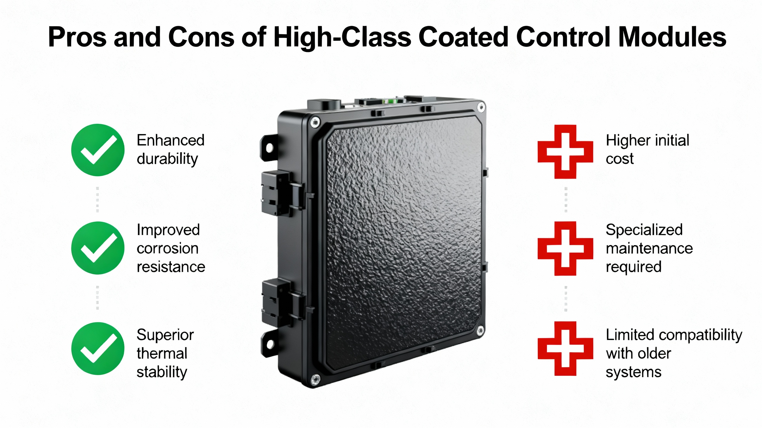
Pros and Cons of a High-Class Coated Control Module
There is no free reliability. The research sources are very honest about the trade-offs.
On the benefit side, you get a dramatic improvement in reliability under moisture and contamination, which Advatek, Qual-Pro, and Centon emphasize as the primary motivation for coating. That means fewer corrosion-driven failures, fewer latent shorts from dendrite growth, and fewer emergency call-outs when a drive or PLC I/O card dies during a storm or a washdown. You can often reduce enclosure complexity, shrink module size, and run higher voltage gradients and tighter spacing without compromising insulation, as Techspray, TT Electronics, and Dymax describe. Coatings also help with vibration and shock, especially flexible silicones, by anchoring components and reducing mechanical fatigue.
On the cost and complexity side, you introduce new manufacturing steps and failure modes. Many chemistries, especially urethane, epoxy, and Parylene, make rework harder or nearly impossible. High-solids and UV-curable coatings can demand dedicated equipment and cure hardware. Thermal management becomes more subtle, because coatings add thermal resistance; Altium specifically warns that some silicone coatings can trap heat if you are not careful about thickness and airflow. Process defects such as de-wetting, blisters, and orange peel are not cosmetic; they are reliability risks that require trained operators and real process control to avoid.
In the context of a “3C-level” control module, the question is less whether you should coat and more what you are willing to spend upfront to avoid outages, field replacements, and damage to your reputation. For installations in remote or hostile locations, or for safety-critical automation, the additional investment in a robust conformal coating process pays back quickly.
A Practical Specification Approach for System Integrators
When I sit down with a control-module vendor to talk about harsh-environment requirements, I structure the conversation around a few concrete topics, all of which are supported by the research notes rather than vague promises.
I begin with the environment and lifetime. That means clarifying expected humidity and condensation patterns, likely chemical exposure, and operating temperature ranges, using the same language you see in automotive ECU and industrial immersion-cooling discussions. I ask them to map that to specific coating chemistries and thicknesses, citing whether their choice behaves more like the acrylic, silicone, urethane, epoxy, or Parylene systems described by Altium, Techspray, HZO, and others.
Next, I ask about standards and workmanship. I look for explicit alignment with IPC-CC-830C for coating qualification and thickness, IPC-A-610 for coverage, and J-STD-001 for soldered assembly requirements, as noted by Centon. I also want to know whether their internal workmanship practices resemble NASA-STD-8739.1’s expectations for polymeric applications: controlled environments, material traceability, operator training, and documented processes.
Then we talk about design and masking. I want to see drawings or CAD exports that define coated and uncoated regions, connector keep-outs, and any special handling for low-standoff parts. I check for problem patterns described by Electrolube, such as tall coated parts adjacent to must-not-coat regions, or dense arrays that will be hard to coat without voids.
Finally, I insist on data. That means inspection methods for production, such as fluorescent inspection or cross-section sampling, and reliability data from SIR, condensation, or other accelerated tests that exercise the coating in the ways Gen3 Systems, HZO, and others describe. Without that evidence, I treat any “3C-class” label as marketing, not engineering.

Short FAQ
Does conformal coating make a control module waterproof?
The research is clear that conformal coatings are moisture-resistant, not waterproof. The Digi-Key forum notes emphasize that for prolonged wet conditions, you still want a suitable enclosure, ideally with drainage and venting, and then conformal coating as the second line of defense. For a high protection class, think of coating plus enclosure plus good mechanical design, not coating alone.
Can I retrofit harsh-class coating to an existing module?
You can, but the risk is high if the original design was not coating-aware. The Electrolube and Altium guidance both highlight that layout, component spacing, and keep-out zoning strongly constrain what coverage is achievable without heroic masking and cycle times. Retrofits often run into edge-coverage issues, trapped flux residues, and inaccessible areas. Where possible, treat coating as part of the initial electrical and mechanical design rather than a late fix.
Is Parylene always the best choice for a 3C-level control module?
Parylene is arguably the most capable conformal coating in the research set, especially on complex 3D geometries, and HZO’s automotive results demonstrate outstanding barrier performance at modest thickness. However, Techspray and others note that its process complexity and lack of rework make it overkill for many standard industrial modules. For many control systems, a well-applied silicone or urethane that follows IPC-CC-830C guidance and passes tough SIR and condensation tests is a more balanced choice.
Closing Thoughts
If your control module has to live in a world of condensation, corrosive gases, and constant vibration, the difference between “painted green board” and “3C-level protection” is the difference between firefighting and sleeping through a storm. The research makes it clear that success comes from treating conformal coating as a full engineering discipline: selecting the right chemistry, designing with coating in mind, enforcing workmanship standards, and proving performance under realistic stress. Do that consistently, and your coated control modules will behave like the reliable project partners your plant expects them to be.
References
- https://snebulos.mit.edu/projects/reference/NASA-Generic/NASA-STD-8739-1.pdf
- https://www.chemtronics.com/8-essential-tips-for-conformal-coating-dip-application?srsltid=AfmBOop1_hCXp1881lhxf4nqnaTMiQcL3T69Z0wkBZcX0pdo7kZOEI_K
- https://www.gen3systems.com/essential-guide-conformal-coating-electronics-importance-challenges-and-best-practices
- https://www.techspray.com/the-essential-guide-to-conformal-coating?srsltid=AfmBOool3v0RC1x6kayZodCi1cXIYwZ81MOcmUtoZpJQwDK1SWd0GIya
- https://www.advateklighting.com/faqs/conformal-coating
- https://www.allpcb.com/allelectrohub/level-up-your-electronics-projects-conformal-coating-for-beginners
- https://resources.altium.com/p/everything-you-need-know-about-conformal-coating
- https://www.brighton-science.com/blog/ensuring-conformal-coating-reliability-with-surface-intelligence
- https://www.centon.com/pages/conformal-coatings
- https://www.designnews.com/electronics/increasing-electronics-reliability-with-conformal-coatings
Keep your system in play!
Top Media Coverage
Categories


Related Products
-
 CENTRAL PROCESSING UNITManufacturer: Siemens
 -
 DC SWITCHING POWER SUPPLYManufacturer: Allen-Bradley
 -
3300 XL 8 mm Proximity ProbesManufacturer: Bently Nevada
-
 GENERAL-PURPOSE ACCELEROMETERManufacturer: Bently Nevada
 -
3300 XL 8 mm Proximity ProbesManufacturer: Bently Nevada
-
COMMUNICATIONS PROCESSORManufacturer: Siemens
-
Argon Laser HeadManufacturer: JDS Uniphase
-
 Standard Armored InterconnectCableManufacturer: Bently Nevada
 -
CPU BOARDManufacturer: Siemens
-
COMMUNICATIONS PROCESSORManufacturer: Siemens

Related articles Browse All
-
 amikong NewsSchneider Electric HMIGTO5310: A Powerful Touchscreen Panel for Industrial Automation2025-08-11 16:24:25Overview of the Schneider Electric HMIGTO5310 The Schneider Electric HMIGTO5310 is a high-performance Magelis GTO touchscreen panel designed for industrial automation and infrastructure applications. With a 10.4" TFT LCD display and 640 x 480 VGA resolution, this HMI delivers crisp, clear visu...
 -
 BlogImplementing Vision Systems for Industrial Robots: Enhancing Precision and Automation2025-08-12 11:26:54Industrial robots gain powerful new abilities through vision systems. These systems give robots the sense of sight, so they can understand and react to what is around them. So, robots can perform complex tasks with greater accuracy and flexibility. Automation in manufacturing reaches a new level of ...
 -
 BlogOptimizing PM Schedules Data-Driven Approaches to Preventative Maintenance2025-08-21 18:08:33Moving away from fixed maintenance schedules is a significant operational shift. Companies now use data to guide their maintenance efforts. This change leads to greater efficiency and equipment reliability. The goal is to perform the right task at the right time, based on real information, not just ...


- Q&A
- Policies How to order Part status information Shipping Method Return Policy Warranty Policy Payment Terms
- Asset Recovery
- We Buy Your Equipment. Industry Cases Amikong News Technical Resources Why choose us
- ADDRESS
-
 32D UNITS,GUOMAO BUILDING,NO 388 HUBIN SOUTH ROAD,SIMING DISTRICT,XIAMEN
Leave Your Comment