
-
Please try to be as accurate as possible with your search.
-
We can quote you on 1000s of specialist parts, even if they are not listed on our website.
-
We can't find any results for “”.
DCS Power Module Fault Diagnosis: Replacement Procedures
In every serious process plant I have worked in, the DCS power modules are the quiet backbone of the entire control system. Controllers, I/O racks, fieldbus interfaces, and operators’ screens all depend on a few inches of hardware that convert incoming AC or DC into clean, stable low-voltage power. When those modules falter, you do not just lose a card; you lose visibility, interlocks, and often production.
Multiple technical sources and field reports agree that power circuits are among the most failure-prone elements in DCS electronics. Technical notes summarized from engineering forums and vendors such as ABB, Amikong, Kaidi Automation, and Just Measure it all highlight power supply degradation as a frequent root cause behind intermittent communication errors, nuisance alarms, random resets, and outright DCS crashes.
This article walks through how an experienced systems integrator judges whether the DCS power module is truly at fault, how to replace it without creating a bigger problem, and how to prevent the same failure from coming back. The focus is practical: what you actually check on the cabinet floor, how to interpret what you see, and how to align repairs with modern lifecycle and regulatory expectations.
Where DCS Power Modules Sit In The Architecture
A Distributed Control System spreads control across many nodes instead of concentrating everything in one controller. As described in maintenance overviews from AutomationCommunity, LLumin, and Mapcon, a typical DCS includes:
Engineering and operator workstations in a central control room, where operators view graphics, trends, alarms, and KPIs.
Controllers in field cabinets, executing control logic for loops and sequences.
I/O modules bridging signals to and from sensors, actuators, and smart field devices.
Industrial networks carrying real-time data between these layers.
Every one of those elements depends on one or more power modules to convert incoming plant power into stabilized low-voltage rails, commonly 24 VDC for controllers, I/O cards, and communication modules. ABB’s own documentation notes this explicitly for their DCS platforms, using the INNIS21 as an example of a module that converts incoming AC to stable low-voltage DC for controllers, I/O, and network interfaces. Fieldbus interface modules such as ABB’s FI840F are particularly sensitive to power quality: unstable supply voltage can produce communication errors and corrupted data.
Power modules are usually installed redundantly for critical systems, and they may be fed from UPS supplies to ride through short disturbances. However, as summarized in technical discussions on eeworld and Kaidi Automation, the power circuitry itself remains one of the most failure-prone parts of DCS electronics. Aging components, poor terminations, corrosion, or inadequate grounding and lightning protection all conspire to make power modules a common starting point when diagnosing serious DCS faults.

Typical DCS Power Module Failure Modes
Although each vendor implements power modules differently, field cases from ABB, Amikong, Kaidi Automation, and others show a consistent set of failure patterns.
No output. The module’s output collapses to zero volts. ABB’s troubleshooting guidance ties this to blown fuses, failed converter stages, or open internal connections. On the plant floor, you see dark controller LEDs, dead I/O racks, and a flood of DCS system alarms.
Unstable output. This is the subtle one that causes the most headaches. In one ABB case study, a 24 VDC supply measured between about 22 and 26 volts even though the 230 VAC input was stable. That unstable output drove intermittent DCS communication errors and occasional system crashes. The root cause was a faulty voltage regulator inside the power module.
Overheating. Power modules that run at or beyond their thermal limits drift, derate, and eventually fail. Amikong’s module-failure guidance describes random controller reboots, brownouts, and intermittent I/O chatter that only appear under high load or on hot days, often traced back to heat-soaked supplies and overloaded 24 VDC rails.
Intermittent resets and nuisance alarms. Aging DCS hardware described by Amikong exhibits voltage fluctuations that trigger random DCS resets, nuisance “chattering” alarms, and sluggish HMI behavior. Related articles on DCS maintenance and fault judgment emphasize that power supply circuits, loose or poorly crimped terminals, and corroded connectors are often behind these elusive problems.
Overload and downstream shorts. The ABB DCS power supply article stresses the importance of distinguishing between a failing power module and a bad load. A shorted downstream component can drag the supply output down or cause repeated fuse failures even when the module itself is healthy.
Environmental and power-quality damage. Kaidi Automation’s analysis shows how poor plug contact, standby power that cannot transfer automatically, undersized breakers, and power quality disturbances such as sags, overvoltage, and undervoltage can burn out circuit boards or prevent them from working properly. The symptoms range from lit alarm indicators and spurious output signals to complete loss of control.
Several sources also underscore the impact of environment: excessive temperature swings, humidity, dust, and corrosive atmospheres degrade power module internals, connectors, and nearby I/O. One study cited by Kaidi Automation found that for analog cards, every 18°F change in temperature reduced measurement accuracy by roughly 0.1 percent, which is a quiet way to erode control performance even before total failure.
These patterns are recognizable if you know what to look for, but power faults are not the only cause of DCS problems. That is why a disciplined, stepwise diagnostic approach matters.
Safety First: Making The Circuit Truly De-Energized
Any work inside a DCS cabinet is an electrical safety task. The PLC module failure guide from Amikong explicitly calls for lockout and tagout in line with OSHA 29 CFR 1910.147 before hands or probes go into energized enclosures. A separate safety-focused article from PLC DCS Pro emphasizes that simply switching off power is not enough; residual energy from capacitors, batteries, or backup sources can still cause shock or arc flash.
Before touching DCS power modules or their conductors, a robust procedure should include:
Clear scope and permits. Treat DCS work as a formal maintenance activity. Use site permit-to-work processes and mark the work zone clearly so no one inadvertently energizes circuits around you.
Lockout and tagout. Isolate upstream breakers or disconnects feeding the cabinet, along with UPS feeds or any alternate supply paths. Apply locks and tags where other personnel expect them, and document what is isolated.
Verification with proper instruments. As PLC DCS Pro notes, a circuit is only truly de-energized when there is no residual voltage or current anywhere in the system, including capacitors, batteries, and backup sources. Use appropriately rated voltage detectors, multimeters, or high-voltage detectors on both line and load side terminals, and confirm zero energy before proceeding.
Use of non-conductive tools and PPE. Even when readings indicate zero, the same source recommends touching conductors first with insulating tools and maintaining proper PPE such as arc-rated clothing, face shields, and insulated gloves appropriate to the site’s standards.
Awareness of natural and induced sources. For outdoor equipment or transmission-related circuits, lightning and induced voltages can re-energize seemingly dead circuits. The de-energization article stresses extra caution in these environments, including bonding, grounding checks, and repeated verification.
Technically, this is “nonproductive” time, but as a project partner I will always insist on it. Replacing a power module is straightforward; recovering from a preventable electrical injury is not.
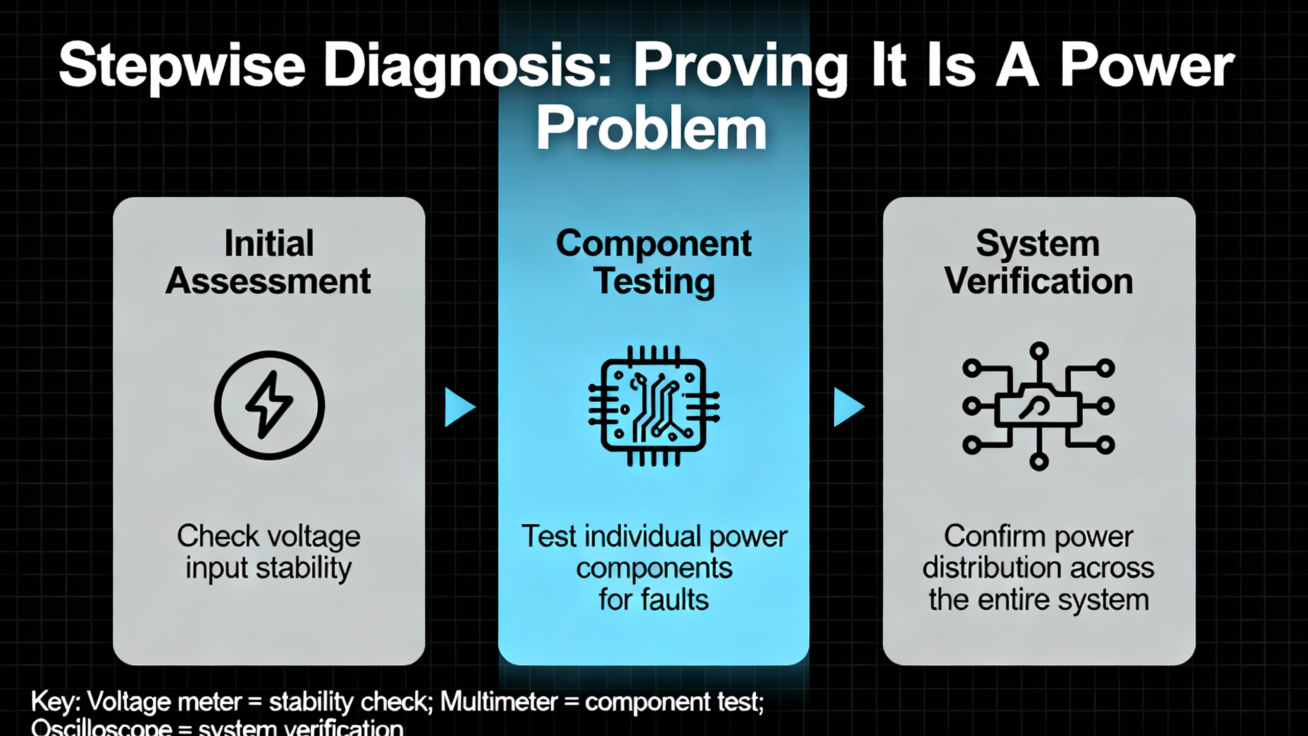
Stepwise Diagnosis: Proving It Is A Power Problem
Once the circuit is safely accessible, the goal is to determine whether the DCS power module is the root cause or just a victim. The most efficient workflows described across Amikong, ABB, IDS, and DCS fault-diagnosis articles all start with the same principle: begin with power integrity, then communications, then I/O and logic.
Start From System Symptoms
Before opening cabinets, use the DCS’s own tools. Articles on DCS fault judgment and industrial DCS troubleshooting recommend using:
Alarms and event lists to see whether AC fail, low DC bus, power supply fault, or cabinet temperature alarms are active or have appeared recently.
Controller, I/O, and network diagnostics to check which nodes are healthy and which report power or communication issues.
Trends of key signals, including power module status bits, controller voltages, and cabinet temperatures where available.
A recurring pattern of controller restarts, simultaneous communication timeouts across multiple I/O racks, or fieldbus modules like ABB’s FI840F reporting communication errors in step with DC bus fluctuations all point toward a power source issue rather than a single bad instrument.
Security alarm panels, like the DSC Power Series described by ADT, categorize trouble conditions into service required, AC loss, low battery, and communication issues. DCS platforms use different terminology, but the idea is similar: a structured set of trouble codes helps you distinguish power-related problems from sensor, communication, or configuration faults. Get familiar with your platform’s equivalent.
Visual And Environmental Inspection
With power proven off and cabinet doors open, a simple visual survey often yields your first solid evidence. Multiple articles on DCS maintenance and aging hardware emphasize looking for:
Board discoloration, soot marks, or melted insulation near power modules or terminals.
Bulging or leaking capacitors and other components on the power board, a classic sign of aging or thermal stress.
Corroded terminals and connectors, especially where humidity, corrosive gas, or marine environments are present. Kaidi Automation notes that humidity above roughly 65 percent can create a moisture film that reduces insulation and accelerates corrosion.
Dust buildup on heat sinks, filters, and fans. Amikong describes “dust-choked cooling paths” as a common precursor to power module deterioration.
Blocked ventilation paths and failed or noisy fans in and around the power module, which increase internal temperature.
Signs of rodents, insects, or accumulated debris that could have caused short circuits or blocked airflow.
Any of these findings strengthen the hypothesis that the power module or its immediate environment is compromised. Even if they are not the immediate cause of the current failure, they are conditions you should correct before re-energizing.
Electrical Measurements: Input, Output, And Load Isolation
The ABB DCS power supply troubleshooting guide and Amikong’s PLC module diagnostic workflow both emphasize measured evidence over intuition.
Check the input. Verify that the incoming AC or DC feeding the power module is within its specified range and at the correct frequency. If the input is out of tolerance, burned modules are a symptom, not the root cause, and you will need to address upstream issues such as undersized breakers, poor contacts, or plant-wide voltage sags.
Measure the DC bus under load. Following Amikong’s workflow, measure the output voltage not just at idle but under typical and peak load. Look for droop, excessive ripple, or oscillation. The ABB example of a 24 VDC output wandering between about 22 and 26 volts, with a stable 230 VAC input, is an archetypal internal regulator fault.
Isolate the load. ABB recommends a simple but powerful step: disconnect or isolate the downstream load from the supply and re-measure the output. If the voltage stabilizes to its rated level, the fault probably lies in a shorted or overloaded downstream component. If the output remains unstable or absent, the power module itself is suspect.
Check connections and terminations. The DCS fault judgment notes and Amikong’s analysis both highlight loose or poorly crimped terminals as frequent culprits. Carefully inspect and retorque power terminals, grounds, and neutral connections, watching for evidence of arcing or overheating.
Monitor temperature. Where possible, use a non-contact thermometer or thermal camera to check module surface temperatures during operation. The PLC module article describes heat-soaked power supplies causing intermittent resets; when you see a module running much hotter than its neighbors, you have another clue.
System-Level Clues And Differentiation
Sometimes the power module is not the primary fault, especially when only one section of the DCS is misbehaving. Use system context:
If many controllers, I/O racks, and networks show faults simultaneously, suspect shared power infrastructure first before individual modules.
If only a single cabinet or I/O island misbehaves while upstream power quality is stable and all other cabinets are healthy, a local power module, its feed, or its environment is more likely.
If communication errors or DCS freezes correlate tightly with plant power events, such as large motor starts or grid flicker, the Kaidi and Amikong analyses suggest looking carefully at ride-through capability, UPS health, and surge or sag protection.
The goal of this phase is not yet to replace anything. It is to arrive at a defensible statement: the power module is good, the load is bad, or the module is the most probable failure point.
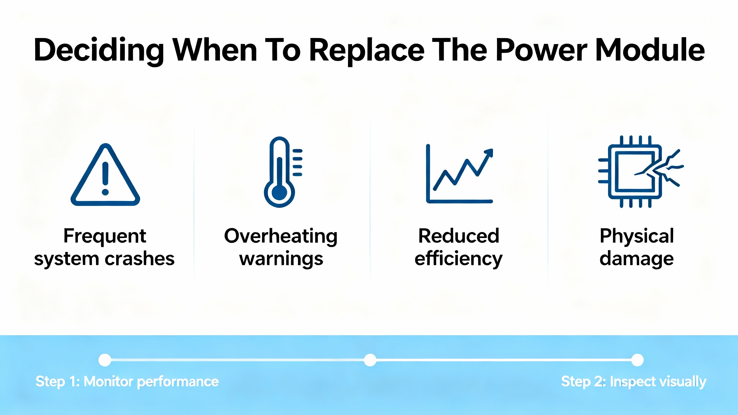
Deciding When To Replace The Power Module
Assuming the evidence points squarely at the module, the next decision is whether you can nurse it along until a better outage window or whether immediate replacement is the lesser risk.
The life-extension guide for aging DCS systems from Amikong points out several early warning cues for failing modules: increasing error codes and communication timeouts, nuisance chattering alarms, sluggish or unresponsive HMI screens, intermittent loop failures, and physical signs such as corrosion, bulging capacitors, dust-choked cooling, unusual buzzing noises, or burning smells. Their advice is clear: when you see a pattern, treat it as a trigger for planned replacement rather than waiting for a catastrophic failure.
In regulated industries, particularly GxP environments, Amikong also emphasizes that low-cost module replacement can often be done without full system revalidation if it is handled as a risk-based “like-for-like” change. That means selecting a functionally equivalent part with the same form, fit, and function, routing the change through formal change control, and documenting impact assessment, Installation Qualification, and targeted Operational Qualification. When done properly, such changes are often classified as minor and avoid full revalidation.
For nonregulated plants, the economics still favor proactive replacement. The same Amikong report notes that planned, predictive maintenance replacing life-limited items such as fans and batteries can reduce unplanned breakdowns by as much as 70 percent. The cost of a power module is usually negligible compared with the cost of a DCS-wide trip.
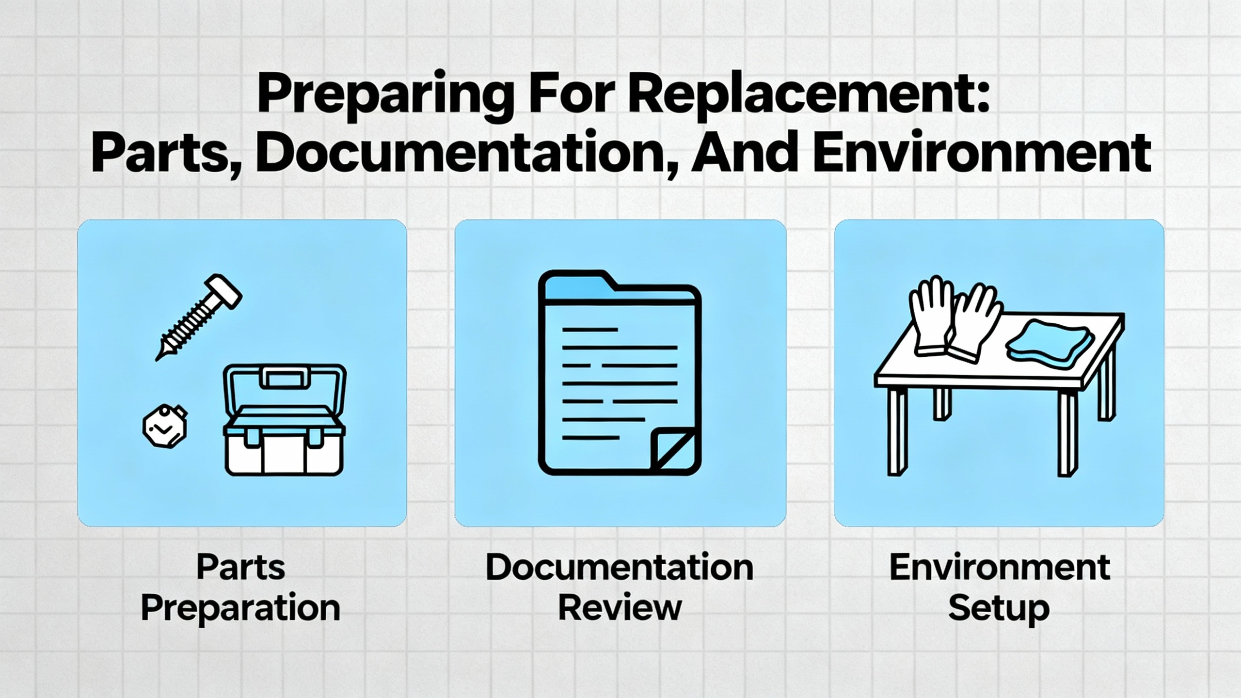
Preparing For Replacement: Parts, Documentation, And Environment
Before pulling a module from a live system, good preparation prevents surprises. The PLC module selection guidance from Amikong, combined with the aging DCS article, gives a clear checklist of considerations when choosing and staging replacement power modules.
Select modules fit for your environment. Ensure the operating temperature rating exceeds your worst-case cabinet conditions with margin. In hot climates or outdoor enclosures, remember that solar load can raise internal temperatures significantly.
Favor strong isolation and diagnostics. Modules whose datasheets specify robust isolation and that offer clear status LEDs and diagnostic outputs will make future troubleshooting faster and reduce cross-talk or ground-loop problems.
Align firmware and tooling. Especially for “smart” power modules or those monitored over networks, ensure firmware is approved for your DCS version and that your engineering software supports their configuration. Mismatched firmware can create subtle compatibility issues.
Verify electromagnetic compatibility. Amikong’s guidance on EMC immunity stresses compatibility with plant EMI and RFI conditions, especially in drive-heavy zones. Proper shield termination guidance in the manual matters because poor grounding and shielding are known contributors to DCS measurement and communication errors in field reports.
Plan wiring and serviceability. Favor modules with clear labeling, pluggable terminals, and enough space for proper ferrules and boots. In an emergency swap, you want terminations that are obvious and accessible.
Confirm lifecycle and sourcing. The life-extension article argues for proactive obsolescence management, including tracking OEM lifecycle notices, arranging “last-time buys” for critical parts, and avoiding unvetted gray-market sources that may carry counterfeit or low-quality products and even cybersecurity risks.
Alongside hardware, gather the latest backups of DCS system configuration, power module settings if applicable, and any relevant drawings. Update your permit-to-work, test plan, and rollback plan so that everyone involved shares the same picture of what “done and safe” looks like.
Replacement Procedures: Doing The Work Without Creating New Problems
Every vendor has specific instructions, and those must be followed. Still, across platforms, real-world procedures converge on a common pattern informed by safety guidance and DCS commissioning practices.
Isolate, Verify, And Document
Apply lockout and tagout on all feeds to the module, including UPS and redundant sources. Verify de-energization with appropriate testers on both incoming and outgoing terminals, as emphasized by PLC DCS Pro.
Record pre-change conditions. Note active alarms, controller and I/O status LEDs, and measured input and output voltages. Take photographs of terminations and module positions. These snapshots help during reassembly and later root-cause reviews.
Label wiring clearly. If terminals are not already well labeled, add temporary tags before removal. This is especially important in older cabinets where documentation may not match reality.
Remove And Inspect The Old Module
Carefully loosen terminal screws or remove pluggable connectors, supporting cables to avoid strain on adjacent modules. Remove the suspect module according to vendor instructions, avoiding flexing the backplane or bending pins.
Inspect the removed module. Look for board discoloration, cracked solder joints, bulging capacitors, and signs of overheating or corrosion. Findings should be logged; they are valuable for reliability analysis and for improving environmental or power-quality controls.
Check the backplane and mating connectors. Ensure there are no signs of damage, arcing, or contamination. Clean dust carefully using appropriate non-conductive tools and methods approved by your site.
Install The Replacement And Restore Power
Insert the new module firmly, verifying that it seats fully into the backplane without undue force. Reconnect terminals, following your photos and labels, and torque connections to vendor or site standards. Confirm that grounding and shielding are landed at the correct points, which is critical given how much DCS reliability literature emphasizes grounding and lightning protection quality.
If the DCS uses redundant power supplies, follow the vendor’s recommended sequence. Many aging DCS guides advise testing redundant units one at a time, ensuring that taking a single unit out of service does not disturb running controllers before you disturb both.
After a final visual check, remove tools and foreign objects from the cabinet, clear the area, and coordinate with operations to restore power in a controlled sequence.
Post-Replacement Testing And Verification
Putting a new power module in the rack is only half the job. You still need to prove that the system is stable and that the original symptoms are gone.
Measure and trend the new module’s output. Immediately after energization, verify that output voltages are within specification and stable under both nominal and peak load. If possible, log these values over time so the DCS or a CMMS platform such as LLumin’s can detect drifts early.
Check DCS diagnostics. Confirm that previous power-related alarms have cleared, that controllers, I/O racks, and networks report healthy status, and that cabinet-level alarms such as temperature or fan faults are resolved.
Validate communication and field interactions. The ABB FI840F example shows how power quality affects fieldbus communication. After replacing the module, watch for recurring communication errors, lost I/O, or abnormal analog readings. If issues persist, the fault may be elsewhere.
Exercise redundancy. Where redundant power supplies or UPS systems exist, test failover behavior in a controlled manner, confirming that the DCS continues operating smoothly if one supply is removed from service.
Update documentation. Record the new module’s model, serial number, firmware revision, and installation date. In regulated environments, update change-control records, validation documents, and drawings as required by your quality system.
If the original fault remains after replacement, your earlier documentation will help you avoid chasing the same path twice and refocus on downstream loads, upstream power quality, or unrelated DCS components.

Preventing Future Power Module Failures
Power modules rarely fail in isolation. They are often messengers of deeper issues in power quality, environment, or maintenance practices. The various DCS maintenance and life-extension articles converge on several preventive strategies.
Control environmental stress. Reports from Kaidi Automation, Amikong, and DCS fault-diagnosis discussions all highlight heat, humidity, dust, and corrosion as long-term killers. Maintain cabinet temperatures within vendor limits, manage humidity to avoid condensation films, keep filters and fans clean, and use appropriate enclosures and gasketing for corrosive or marine environments. For outdoor or high-heat installations, consider sunshades and small anti-condensation heaters as recommended in field experience summaries.
Improve grounding and lightning protection. Articles on DCS failure losses and fault judgment emphasize that poor grounding and lightning protection can create ground potential differences large enough to disturb or damage electronics. Single-point grounding for sensitive circuits, proper bonding of cable trays and shields, and integrated lightning and control system grounding designed to relevant standards all reduce stress on power modules.
Maintain power quality and UPS health. Kaidi Automation’s analysis of power disturbances shows how voltage sags, surges, and mismatched loads can burn cards or disrupt operation. Proactive measures include right-sizing supplies with headroom, segregating “dirty” loads like large drives onto separate feeders, employing surge protection, and regularly testing UPS performance and replacing batteries at end-of-life instead of after failure.
Practice structured preventive maintenance. The aging DCS article advocates regular inspections, cleaning, and schedule-based replacement of life-limited items such as fans and backup batteries. Instrument maintenance guidance from Zapium extends this checklist thinking to instrumentation; the same philosophy applies to DCS power: torque checks on terminals, verification of cabinet and power-supply diagnostics, and periodic measurement of supply voltages under real production load.
Leverage CMMS and condition monitoring. Maintenance platforms such as CMMS solutions described by LLumin and Mapcon can tie DCS diagnostic data to preventive work orders, tracking KPIs such as uptime, mean time between failures, and maintenance response time. For high-value assets, vibration and temperature monitoring systems feeding the DCS can forewarn of process-side issues that might cause power disturbances, such as failing motors or generators.
Plan obsolescence and spares. The Amikong life-extension guide stresses careful spares strategies: combining OEM legacy support and qualified third-party suppliers with in-house test and warranty capability, while avoiding gray-market sources. Blanket purchase orders and “last-time buys” for critical modules help limit lead-time risks.
Build skills and procedures. DCS fault-handling articles from automation communities and professional networks emphasize that maintenance personnel skills and discipline are as important as hardware. Regular training, clear diagnostic workflows, and robust change-management processes prevent many “man-made” DCS failures that statistics show dominate in mature systems.
Frequently Asked Questions
How do I know when to replace a marginal DCS power module instead of monitoring it?
When you see a consistent pattern of power-related alarms, intermittent controller resets, or DCS communication errors tied to a particular supply, and especially when physical inspection shows aging signs such as bulging capacitors, corrosion, dust-choked cooling, or abnormal heat, the life-extension guidance from Amikong suggests treating that module as a candidate for planned replacement. Waiting until it fails hard usually costs more in downtime than the module is worth, and predictive maintenance studies cited there indicate that proactive replacement of such components can reduce unplanned breakdowns dramatically.
Can I replace a power module online if there is redundancy?
Some DCS architectures support online replacement of redundant power modules, but whether that is safe depends entirely on the vendor design and system configuration. Aging DCS case studies mention redundant power units, yet they also document failures when redundancy was misunderstood or misused. Never assume online replacement is safe based only on redundancy; follow the vendor’s procedure, validate behavior in a noncritical test scenario where possible, and always apply site electrical safety rules, including lockout and tagout for any circuits you physically touch.
What if the exact power module is obsolete and only refurbished parts are available?
The legacy-support article from Amikong recognizes this scenario as common in aging DCS systems. Their recommendation is to avoid uncontrolled gray-market purchases and instead work with qualified suppliers who can provide tested refurbished units with warranty, alongside OEM or authorized legacy programs. For regulated environments, they emphasize risk-based “like-for-like” evaluation, ensuring that replacements match form, fit, and function, are documented under formal change control, and are accompanied by appropriate qualification tests. Where risk is high and long-term support is poor, they suggest phased modernization and asset recovery to fund upgrades.
As a veteran integrator, I treat DCS power modules as strategic components, not consumables. When you diagnose them rigorously, replace them deliberately, and design the surrounding power and environment intelligently, they fade back into the background where they belong, quietly powering safe and stable operations shift after shift.
References
- https://alarm.net/wp-content/uploads/2018/08/Troubleshooting-Guide-DSC-Tech-Support.pdf
- https://jiweiauto.com/dcs-systems-fault-diagnosis-troubleshooting.html
- https://www.kaidi86.com/how-to-reduce-the-unnecessary-loss-dcs-failure.html
- https://www.amikong.com/n/aging-dcs-life-extension
- https://automationcommunity.com/dcs-maintenance/
- https://www.br-transmitter.com/blog/how-to-troubleshoot-the-power-supply-problems-in-abb-dcs-1828344.html
- https://en.eeworld.com.cn/bbs/thread-574075-1-1.html
- https://idspower.com/common-issues-control-systems/
- https://instrunexus.com/controlling-output-devices-understanding-dcs-output-modules/
- https://www.wevolver.com/article/mastering-distributed-control-systems-a-comprehensive-guide-to-dcs-architecture-components-and-applications
Keep your system in play!
Top Media Coverage
Categories


Related articles Browse All
-
 amikong NewsSchneider Electric HMIGTO5310: A Powerful Touchscreen Panel for Industrial Automation2025-08-11 16:24:25Overview of the Schneider Electric HMIGTO5310 The Schneider Electric HMIGTO5310 is a high-performance Magelis GTO touchscreen panel designed for industrial automation and infrastructure applications. With a 10.4" TFT LCD display and 640 x 480 VGA resolution, this HMI delivers crisp, clear visu...
 -
 BlogImplementing Vision Systems for Industrial Robots: Enhancing Precision and Automation2025-08-12 11:26:54Industrial robots gain powerful new abilities through vision systems. These systems give robots the sense of sight, so they can understand and react to what is around them. So, robots can perform complex tasks with greater accuracy and flexibility. Automation in manufacturing reaches a new level of ...
 -
 BlogOptimizing PM Schedules Data-Driven Approaches to Preventative Maintenance2025-08-21 18:08:33Moving away from fixed maintenance schedules is a significant operational shift. Companies now use data to guide their maintenance efforts. This change leads to greater efficiency and equipment reliability. The goal is to perform the right task at the right time, based on real information, not just ...


- Q&A
- Policies How to order Part status information Shipping Method Return Policy Warranty Policy Payment Terms
- Asset Recovery
- We Buy Your Equipment. Industry Cases Amikong News Technical Resources Why choose us
- ADDRESS
-
 32D UNITS,GUOMAO BUILDING,NO 388 HUBIN SOUTH ROAD,SIMING DISTRICT,XIAMEN
Leave Your Comment