
-
Please try to be as accurate as possible with your search.
-
We can quote you on 1000s of specialist parts, even if they are not listed on our website.
-
We can't find any results for “”.
Getting Clean Counts: Encoder Interface Modules with Differential Input Channels
When a project moves from the CAD screen to the plant floor, encoder wiring is where many otherwise solid designs start to creak. I have seen perfectly good motors and drives behave erratically because someone treated an encoder like just another digital input. The result is familiar: skipped counts, “random” positions, and hours lost in troubleshooting.
Encoder interface modules with differential input channels exist to prevent that outcome. They bridge the gap between noisy, real-world signals at the machine and the clean, deterministic data your controller needs. In this article I will walk through what these modules do, why differential inputs matter, and how to choose and apply them in real industrial environments.
Why A Simple Digital Input Is Not Enough
In theory, you can connect an encoder directly to a PLC’s discrete inputs and decode the signals in ladder or structured text. A user on AutomationDirect’s community forum tried exactly that. The goal was straightforward: measure a shaft angle using an absolute rotary encoder in a Productivity PLC system. An initial 2,048 pulses‑per‑revolution encoder overwhelmed the chosen digital input card, so the user switched to a Koyo absolute encoder with a 9‑bit Gray code output over a 360° range.
The PLC read each Gray‑code bit individually through discrete inputs, then combined them into a 9‑bit value in software.
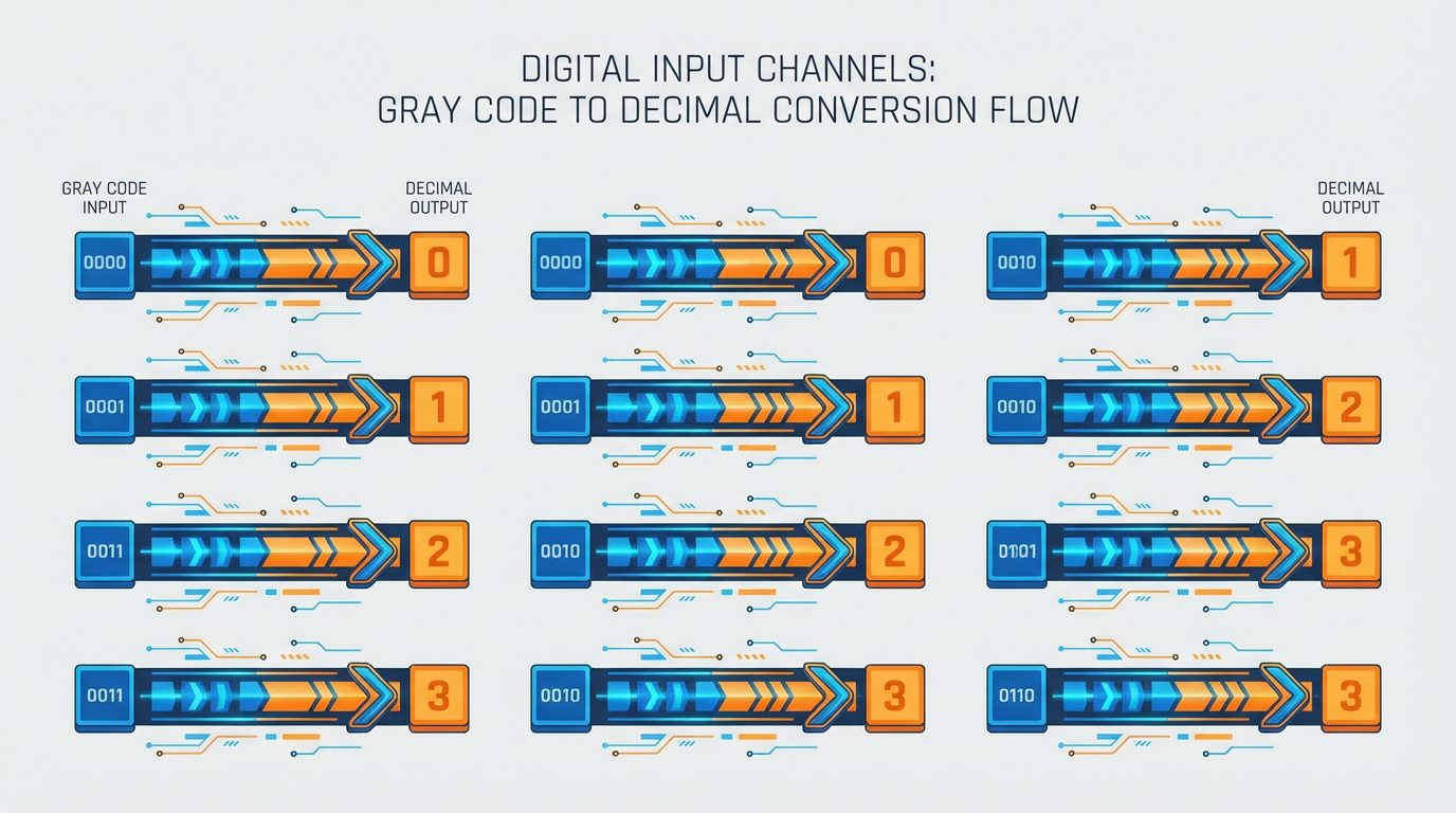
Even after trimming unused codes according to the datasheet, the resulting positions did not step neatly from 0 to 360 degrees. Instead, the values looked random. The likely culprits were familiar to anyone who has done this in anger: inconsistent bit‑to‑channel mapping, incorrect Gray‑to‑binary conversion, or signal timing issues on the digital inputs.
That case illustrates a broader point echoed in practical guides from Phidgets, Dynapar, and Rockwell Automation. Encoders are not just “fast switches.” They are precision feedback devices, often running at high resolution and high speed. Expecting general‑purpose PLC inputs to handle that job without help is optimistic, especially in a plant full of noise, long cable runs, and mixed signal levels.
Encoder interface modules sit in that gap. They are purpose‑built to receive encoder signals, condition them, count them correctly, and present clean position or speed data to your control system. When those modules offer differential input channels, they also tackle the electrical noise that plagues real‑world installations.
Encoders In Plain Language
Before diving into interface modules, it is worth aligning on what the encoder is actually sending.
DigiKey’s encoder overview and multiple vendor application notes all converge on the same definition: a rotary encoder measures angular position or motion and converts it to electrical signals for your controller. Those signals come in two main flavors: incremental and absolute.
Incremental (Quadrature) Encoders
Incremental encoders report motion relative to a starting point. As the Phidgets Encoder Guide explains, they typically output two digital channels, called A and B, which toggle between low and high voltages. These channels are shifted by 90 electrical degrees, a scheme called quadrature. By counting transitions and watching which channel leads, an interface can determine both how far the shaft has turned and in which direction.

Many incremental encoders add a third “index” channel that produces one pulse per revolution. Combined with homing logic, that index allows the controller to establish a repeatable zero reference even though the raw signals are purely relative.
Incremental encoders shine in speed control and relative positioning where homing at startup is acceptable. They also tend to be simpler and lower cost than their absolute counterparts, a point reinforced by Omch and Rockwell Automation. However, they forget their position when power is removed; after a power cycle, the control system must re‑home or otherwise re‑establish the reference.
Absolute Encoders And Gray Code
Absolute encoders take a different approach. As described by Omch, Arrow Electronics, and several encoder manufacturers, absolute devices assign a unique digital code to every shaft position within their range. On power‑up, the controller reads the code and immediately knows the actual position—no homing move required.
Single‑turn absolute encoders cover one revolution; multi‑turn versions also count the number of turns, often up to several thousand, allowing true absolute position over a long stroke or rotation range. Rockwell Automation notes that absolute encoders are the right fit wherever you cannot tolerate uncertainty after a power loss or unexpected movement, such as safety‑critical axes or expensive, slow‑moving machines.
Many parallel absolute encoders use Gray code on their disks. Phidgets explains why: in Gray code, only one bit changes between adjacent positions, reducing the chance that a momentary misread during a transition produces a wildly incorrect value. The AutomationDirect case study shows the flip side: if the Gray‑code bits are wired or decoded incorrectly, the resulting “angle” will appear random.
Modern absolute encoders often hide the Gray code inside electronics and expose only a serial or fieldbus protocol such as SSI, BiSS, EnDat, or CANopen, as described by Dynapar, Omch, and HEIDENHAIN. Even then, the physical layer that carries that serial data is frequently differential. That is where differential input channels on interface modules come into play.
Single‑Ended And Differential Encoder Outputs
At the electrical level, encoder outputs fall broadly into single‑ended and differential categories. Phidgets emphasizes this distinction in their Encoder Guide, classifying quadrature output types into these two families.
Single‑ended outputs share a common reference. A simple mechanical encoder might use brushes that connect a signal line to ground when over a conductive area; basic optical encoders can use phototransistors that “sink” current to ground, a style often called open‑collector or current‑sinking. Omch and others also refer to single‑ended logic‑level outputs as TTL or HTL, depending on voltage ranges.
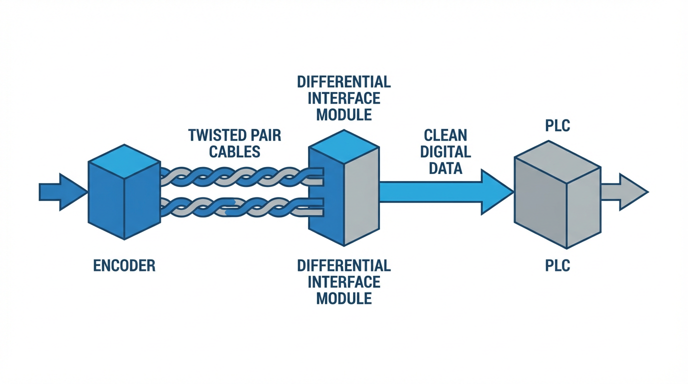
Differential outputs, by contrast, use two complementary signals per channel rather than a single line referenced to ground. Phidgets notes that quadrature encoders can present each A, B, and index channel as a differential pair rather than a single wire. In practice, these pairs are typically carried over twisted pairs in an encoder cable and received by line‑receiver circuits on the interface module.
Differential signaling is the same basic idea that underlies robust industrial links like RS‑485, which Industrial Ethernet and encoder‑interface articles highlight for its long‑cable and noisy‑environment performance. Instead of relying on a single wire’s voltage to ground, the receiver looks at the difference between the two lines in a pair. Common‑mode noise tends to affect both wires similarly and cancels out at the receiver, which is a significant advantage on long runs past VFDs, welders, and contactors.

For practical purposes at the panel, this means a “differential encoder interface module” is built to terminate and interpret these complementary A/A‑, B/B‑, and index pairs correctly, instead of assuming a single 0–5 V or 0–24 V edge against a clean ground.
Why Use An Encoder Interface Module At All?
Phidgets makes a blunt recommendation in their documentation: do not try to decode a fast quadrature signal directly with general digital inputs. Their reason is straightforward. Many digital inputs sample too slowly to catch every edge at higher encoder resolutions and speeds, especially if you want 4x decoding, where every rising and falling edge on both channels counts.
The AutomationDirect Gray‑code example shows the same theme on the absolute side. Discrete inputs were technically capable of reading the bits, but the decoding workload and sensitivity to wiring details turned a simple application into a debugging exercise.
Encoder interface modules solve three problems at once.
First, they provide the electrical front‑end to match real encoder outputs. Phidgets interfaces, for example, supply the typical 5 V power rail many optical encoders require, and they include pull‑up resistors for open‑collector outputs. Differential‑capable modules add the line receivers needed for complementary signals. This is far more than a bare PLC input expects.
Second, they handle the timing and counting. The module’s hardware is designed to recognize quadrature edges at the necessary speed. Phidgets describes how an interface can operate in 1x, 2x, or 4x modes by counting only full cycles, both edges on each channel, or every edge. The module converts this into a position count variable, insulating your control logic from raw edge processing.
Third, they translate to formats that controllers understand. Dynapar’s overview of encoder interfaces outlines the spectrum: direct parallel words, SSI or BiSS serial streams, and full fieldbuses like Profibus, DeviceNet, CANopen, EtherCAT, and Profinet. An encoder module may expose its data as a simple up/down count on a PLC backplane, a synchronous serial word, or as process data on an Ethernet‑based network. In every case, it hides the messy edge counting and level handling.
In short, the module is the specialist between a sensitive feedback device and a general‑purpose control platform.
Inside A Differential Encoder Interface Module
Implementations vary, but most differential encoder interface modules for incremental encoders share the same core blocks.
On the input side, each differential pair from the encoder terminates into a receiver circuit. Dynapar’s comparison of parallel and serial encoder links emphasizes the use of twisted pairs for each bit or serial channel; the module adds proper termination and biasing to those pairs so that signal integrity holds over the entire cable length. For incremental encoders, that typically means receivers for A/A‑, B/B‑, and index pairs.
Behind the receivers, a quadrature decoding engine interprets the logic levels. As Phidgets explains, this block decides whether to perform 1x, 2x, or 4x decoding and maintains a position counter and direction state. On high‑performance drives and controllers, manufacturers like HEIDENHAIN and Renesas often integrate this functionality directly alongside motor‑control timers so that current, velocity, and position loops can run tightly coupled to encoder feedback.
On the output side, the module presents position, speed, and sometimes diagnostics to the host. Dynapar’s interface protocol guide shows the options. For simple point‑to‑point applications, SSI or BiSS provide a clocked serial word containing position and status.
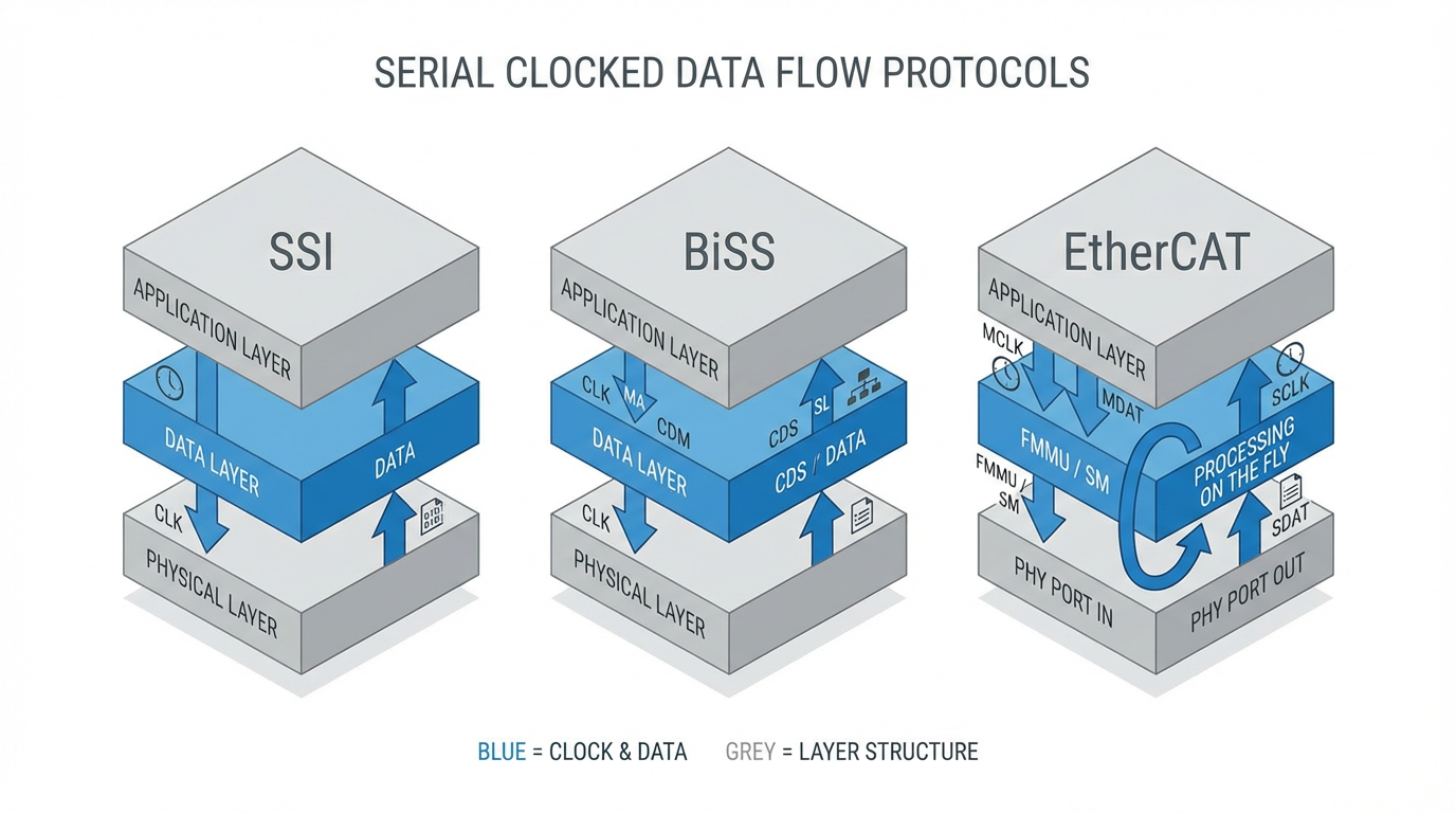
For multi‑axis designs, fieldbus or industrial Ethernet options such as CANopen, Profibus, DeviceNet, EtherCAT, or Profinet allow a single controller to read many encoders over one network, sometimes with cycle times on the order of microseconds.
Some modern encoder solutions, described in Industry‑focused pieces from HEIDENHAIN and IEB Media, go further by embedding condition‑based monitoring. They integrate MEMS accelerometers and temperature sensors into the encoder body and stream vibration and health data back over the same differential link, turning the feedback channel into both a position sensor and an early warning system.
Comparing Single‑Ended And Differential Approaches
For many engineers, the choice between a simple single‑ended encoder input and a differential interface module comes down to reliability under plant conditions. The differences can be summarized at a high level.
| Aspect | Single‑Ended Inputs (Basic DI or TTL) | Differential Encoder Interface Module |
|---|---|---|
| Signal reference | One wire per channel referenced to common ground | Complementary pairs per channel interpreted as a voltage difference |
| Noise and cable length | Sensitive to ground noise and long runs | Designed for twisted‑pair cabling and noisy industrial environments |
| Decoding responsibilities | Controller must count edges and handle direction | Module performs quadrature decoding and often scaling |
| Protocol flexibility | Typically limited to simple ABZ signals | Can support ABZ plus SSI, BiSS, fieldbus, or Ethernet feedback |
| Integration effort | Lower hardware cost but higher software and debug time | Higher hardware sophistication but cleaner integration path |
The table reflects trends described across Phidgets’ signal discussions, Dynapar’s protocol comparisons, and HEIDENHAIN’s encoder interface recommendations. In clean, compact systems with low resolution and short cables, single‑ended inputs may suffice. As soon as you start pushing higher resolutions, higher speeds, or longer cable runs past heavy equipment, differential modules earn their keep.
Speed, Resolution, And Module Capability
Every encoder interface module has limits. Arrow Electronics points out that encoder speed capability is governed by two ceilings: the mechanical speed in revolutions per minute and the electronic frequency response of both the encoder and the reading electronics. DigiKey’s TechForum article on rotary encoders adds that incremental encoders can span from a few hundred up to many thousands of counts per revolution.
Combine those facts with Phidgets’ 4x decoding explanation, and a pattern emerges. Higher counts per revolution and higher RPM produce higher edge rates. If the module’s input circuitry or internal logic cannot process those edges reliably, counts will be lost.
Practical selection therefore means matching three things. You must know the encoder’s resolution, understand the maximum shaft speed, and verify that the interface module’s specified maximum count frequency and decoding mode are adequate. If you have an encoder with very fine resolution on a fast‑moving shaft, a module limited to low edge rates may behave no better than the PLC digital inputs you were trying to escape.
Absolute protocols raise similar concerns in the serial domain. Dynapar notes that SSI and BiSS links are clocked, often in the megahertz range, with cable‑length‑dependent limits. Industrial Ethernet feedback protocols such as EtherCAT and Profinet can achieve very short cycle times, but only when the underlying physical layer and transceivers are specified accordingly. Articles from IEB Media on future encoder interfaces even discuss single‑pair Ethernet targeting latencies around microseconds for extremely tight control loops.
The lesson for system integrators is simple. Do not treat “differential encoder interface module” as a generic commodity. Check its specified resolution, maximum count rate or serial clock, and network bandwidth against the encoder and application requirements.
Environmental And Safety Considerations
HEIDENHAIN’s guidance on choosing encoders emphasizes that the environment is just as important as resolution. Exposed encoders deliver top accuracy in clean environments like semiconductor tools, while sealed encoders in robust housings handle dust, coolant, and chips in machine tools. Manglam’s discussion of heavy‑duty encoder applications adds scenarios such as mining equipment, cranes, and steel processing lines, where vibration, shock, dust, and moisture are the norm.
Differential input modules are well aligned with those harsher contexts because they are designed around balanced, twisted‑pair signals that tolerate electrical noise. However, you still need to choose hardware with appropriate ingress protection, temperature ratings, and mechanical robustness. IEB Media highlights that advanced industrial encoder systems can operate in wide temperature ranges and deal with significant vibration, but only when the entire chain, from sensor to interface electronics, is specified for that duty.
Safety is another axis. RLS’s encoder selection handbook introduces concepts like redundancy and Safety Integrity Level. In safety‑critical systems, it is common to use redundant encoder channels or dual encoders, sometimes feeding into independent differential interface modules, so that one can cross‑check the other. Modern protocols such as EnDat are designed for functional safety up to high levels and can transmit both position and diagnostic data for online monitoring.
When you select an encoder interface module for a safety‑related axis, you must consider not only whether it has differential inputs, but also whether its diagnostics, error reporting, and supported protocols align with your safety architecture.
Matching The Module To Your Control Architecture
From a systems‑integrator perspective, an encoder interface module is not just about signal cleanliness; it must also fit your controller’s way of working.
Omch’s overview of encoder outputs spans simple quadrature signals, synchronous serial interfaces such as SSI and BiSS, and a wide range of networked outputs including CANopen, PROFINET, EtherCAT, and DeviceNet. Dynapar’s interface comparison walks through similar territory from the encoder side. Renesas’s whitepaper on encoder interface support adds the controller angle, arguing for drive and PLC platforms that can handle incremental ABZ, Hall/UVW patterns, analog SinCos, and multiple serial protocols on the same hardware.
In practice, this means you should first decide where you want the “brain” of the feedback loop to reside. If a PLC is handling motion via integrated technology objects, you may prefer encoder modules that present counts or positions directly to the PLC’s backplane, perhaps via a proprietary high‑speed interface. If dedicated servo drives handle the control loops, and the PLC only supervises, then encoder interfaces may be part of the drive rather than a separate module.
If your architecture is network‑centric, fieldbus or Industrial Ethernet encoder modules that speak the same protocol as your I/O and drives simplify wiring and diagnostics. Heidenhain’s EnDat‑based solutions and various EtherCAT encoder modules are examples of this approach: the encoder and its interface become a smart node on the same deterministic network that your controllers already use.
A flexible approach, recommended by Renesas, is to choose controllers and modules with software‑configurable encoder interfaces. When the hardware can be reconfigured in firmware to handle different encoder types and protocols, you can adapt to new feedback devices without redesigning your I/O or backplane.
Practical Advice From The Field
Over the years, some patterns have repeatedly paid off when deploying encoder interface modules with differential inputs.
The first is to treat encoder selection, interface module selection, and mechanical design as a single problem, not three separate ones. US Digital’s guidance on choosing encoders recommends thinking in terms of the application’s “world”: motion type, speed, environment, available power, cable run lengths, and budget. RLS frames selection as a three‑step process: choose the encoder type, define specifications like resolution and accuracy, then choose added features like multi‑turn capability and safety. Extending that mindset, you should decide in the same sweep how the encoder will mount mechanically, how far it is from the control cabinet, and what interface module can realistically live with those constraints.
The second is to avoid “creative” electrical hacks when the right interface exists. Phidgets warns specifically against trying to decode quadrature using generic digital inputs because sampling speed and edge detection are rarely good enough. The AutomationDirect Gray‑code scenario shows the same issue in a different form. It is tempting to squeeze more life out of existing PLC input cards, but the hours spent chasing intermittent miscounts typically cost more than a proper differential encoder module.
The third is to take diagnostics seriously. Modern encoder interfaces, especially those designed for Industry 4.0 environments as described by Industrial Machinery Digest and IEB Media, can report not just position but also internal status, operating statistics, and sensor data. When you route that data back to your control or maintenance systems, you gain early warning of degrading encoder signals, rising temperatures, or mounting issues before they cause unplanned downtime.
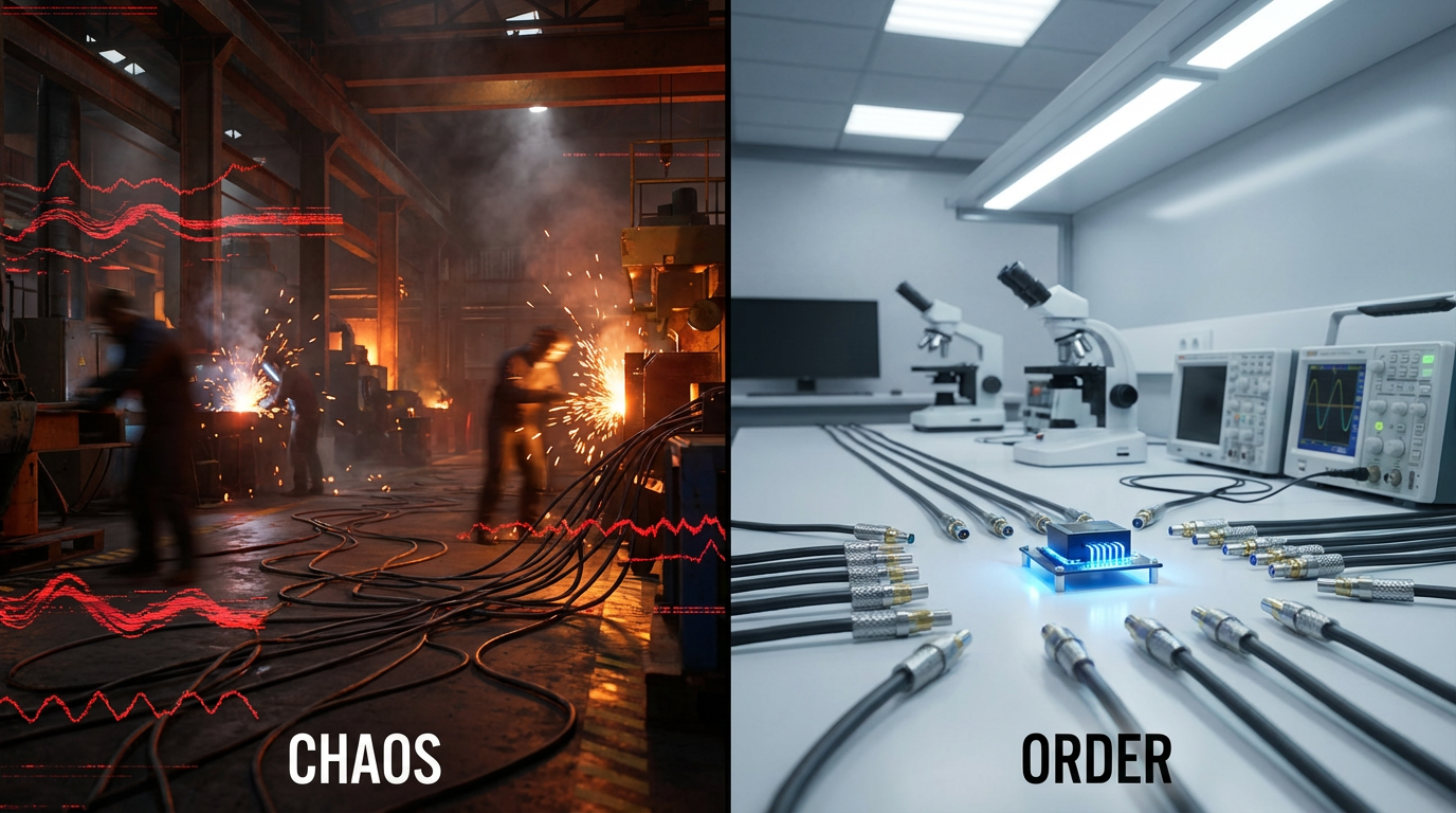
Finally, test under realistic conditions. It is easy to prove an encoder and interface module on a clean lab bench with short cables. The true test is at full production speed, with drives switching, conveyors running, and welders or other high‑energy devices active. If the module’s differential inputs and decoding logic survive that with clean, repeatable position data, you have the right combination.
Frequently Asked Questions
When do I really need a differential encoder interface module instead of simple digital inputs?
You can sometimes get away with simple single‑ended inputs for low‑resolution encoders, short cable runs, and noncritical applications where occasional miscounts do not matter. As soon as you raise the stakes on accuracy, run longer cables through noisy environments, or move to high‑resolution or high‑speed encoders, the balance shifts. Modules with differential inputs and dedicated decoding logic are designed specifically for those conditions and are strongly recommended.
Will a differential module help with absolute encoders that use serial protocols?
Yes, in many cases. Dynapar and Omch note that serial absolute protocols like SSI, BiSS, EnDat, and various fieldbuses often ride on top of differential physical layers similar to RS‑485. A module or controller input built for those protocols will include appropriate differential receivers and timing logic. For parallel Gray‑code or binary absolute encoders, dedicated modules can likewise provide differential inputs per bit along with Gray‑to‑binary conversion, avoiding the bit‑level pitfalls seen in ad‑hoc PLC implementations.
How should I approach safety when using encoders and differential interface modules?
Start by clarifying the safety functions the axis must perform and the associated integrity level. RLS highlights redundancy, diagnostics, and Safety Integrity Level as key parameters. Many modern encoder systems and protocols, such as safety‑rated versions of EnDat or fieldbus encoders, are designed with functional safety in mind. Choose interface modules that can participate in your safety architecture, whether that means redundant channels, plausibility checks between encoders, or explicit integration into safety PLCs and networks.
In the end, encoder interface modules with differential input channels are not glamorous components, but they are the quiet enablers of precise, reliable motion. If you specify them thoughtfully—matched to your encoder, environment, and control architecture—they will disappear into the background, doing their job day after day. That is exactly what you want from a feedback system and exactly what a veteran integrator looks for in a long‑term project partner.
References
- https://www.manglamelectricals.com/applications-of-rotational-encoders-in-heavy-duty-industries
- https://www.dynapar.com/knowledge/encoder-basics
- https://www.microchipusa.com/electrical-components/decoding-the-role-of-encoders-in-modern-technology?srsltid=AfmBOoqNYtXjLbHg0mEjW2yqKOlD_t5A7fPRmsBghso9T1TzX_nGultt
- https://www.omch.com/what-is-an-encoder/
- https://www.phidgets.com/docs/Encoder_Guide?srsltid=AfmBOooKIBO3pqi-RfyIO-XlbOzsnZ_62xeQeVIru5xwtUgYBaoRKBMm
- https://www.zhiyingmotor.com/articledetail/choosing-the-right-encoder-for-your-linear-motion-system.html
- https://www.balluff.com/en-us/news/expanded-encoder-portfolio
- https://forum.digikey.com/t/understanding-rotary-encoders-key-types-technologies-and-use-cases/44606
- https://www.heidenhain.us/resources-and-news/choosing-right-encoder-application/
- https://rgbelektronika.eu/news/how-to-check-an-encoder-a-technical-guide-for-automation-and-service-technicians/
Keep your system in play!
Top Media Coverage
Categories


Related articles Browse All
-
 amikong NewsSchneider Electric HMIGTO5310: A Powerful Touchscreen Panel for Industrial Automation2025-08-11 16:24:25Overview of the Schneider Electric HMIGTO5310 The Schneider Electric HMIGTO5310 is a high-performance Magelis GTO touchscreen panel designed for industrial automation and infrastructure applications. With a 10.4" TFT LCD display and 640 x 480 VGA resolution, this HMI delivers crisp, clear visu...
 -
 BlogImplementing Vision Systems for Industrial Robots: Enhancing Precision and Automation2025-08-12 11:26:54Industrial robots gain powerful new abilities through vision systems. These systems give robots the sense of sight, so they can understand and react to what is around them. So, robots can perform complex tasks with greater accuracy and flexibility. Automation in manufacturing reaches a new level of ...
 -
 BlogOptimizing PM Schedules Data-Driven Approaches to Preventative Maintenance2025-08-21 18:08:33Moving away from fixed maintenance schedules is a significant operational shift. Companies now use data to guide their maintenance efforts. This change leads to greater efficiency and equipment reliability. The goal is to perform the right task at the right time, based on real information, not just ...


- Q&A
- Policies How to order Part status information Shipping Method Return Policy Warranty Policy Payment Terms
- Asset Recovery
- We Buy Your Equipment. Industry Cases Amikong News Technical Resources Why choose us
- ADDRESS
-
 32D UNITS,GUOMAO BUILDING,NO 388 HUBIN SOUTH ROAD,SIMING DISTRICT,XIAMEN
Leave Your Comment