
-
Please try to be as accurate as possible with your search.
-
We can quote you on 1000s of specialist parts, even if they are not listed on our website.
-
We can't find any results for “”.
Linear Motor Drive Controllers for High‑Speed Positioning Applications
When you strip away the marketing gloss, a linear motor drive controller has one job: turn electrical power into predictable, high‑speed, micron‑level motion without breaking your machine, your product, or your schedule. As someone who has lived through enough commissioning nights on CNC lines, semiconductor tools, and inspection systems, I can say that the controller is where high‑speed positioning projects are either de‑risked or doomed.
This article walks through how linear motor drive controllers work, what makes high‑speed positioning so demanding, and how to design, tune, and maintain these systems so they stay accurate at real production speeds. The focus is on direct‑drive linear motors with electronic controllers, drawing on practical experience backed by documented work from sources such as Wikipedia, HEIDENHAIN, MDPI, IEEE, CSK Motion, Iris Dynamics, ITG Motor, and others.
Why Linear Motors Dominate High‑Speed Positioning
A linear motor is essentially a rotary motor that has been “unrolled” so that the stator and rotor form a straight track. Instead of generating torque, the motor produces thrust directly along its length. Sources such as Wikipedia and HEIDENHAIN describe the typical structure as a stationary stator with current‑carrying coils and a moving element with magnets or conductive plates. When the coils are energized, electromagnetic forces act on the mover and generate linear motion.
By eliminating intermediate mechanical components such as ball screws, belts, and gearboxes, linear motors remove backlash and much of the compliance that limits dynamic performance. HEIDENHAIN and other industrial suppliers emphasize that direct‑drive linear stages can reach accelerations on the order of tens of meters per second squared and axis speeds of several meters per second. In more familiar terms, that is equivalent to accelerations of roughly dozens of feet per second squared and travel speeds around 10 feet per second or more. Wikipedia notes that modern synchronous linear actuators used in machine tools achieve velocities of about 2 meters per second, roughly 7 feet per second, with micron‑level positioning accuracy.
Those characteristics are why linear motors have become standard in high‑accuracy CNC machines, semiconductor steppers, pick‑and‑place equipment, and high‑speed Cartesian robots. A 2024 estimate cited on Wikipedia puts the high‑accuracy CNC and industrial robot linear motor market at about $1.8 billion, with millions of motors in service.
Of course, you do not get any of that performance automatically. The controller determines whether the axis actually reaches those speeds, holds the required tolerances, and survives real‑world disturbances. To understand what a linear motor drive controller must handle, it helps to distinguish the main motor types used in positioning.
Linear Synchronous vs Linear Induction Motors
The AI‑focused teaching materials from AI Future School summarize the dominant types of industrial linear motors:
Linear synchronous motors use a traveling magnetic field in the stator synchronized with permanent magnets on the mover. These are the workhorses of high‑speed, high‑accuracy positioning. They excel where you need high velocity and tight position control, such as precision machine tools, semiconductor handling, and maglev transport.
Linear induction motors induce currents in a conductive secondary, typically an aluminum or similar plate. They are mechanically simple and robust, and better suited for applications that need large thrust at more modest speeds, such as heavy conveyors, amusement rides, or certain transit systems.
For high‑speed positioning axes inside machines, linear synchronous motors are the usual choice. Controllers are therefore designed around precise field‑oriented or synchronous control with high‑resolution position feedback.
What a Linear Motor Drive Controller Actually Does
An application note from ITG Motor describes a linear motor controller as the “brain” that converts electrical input into accurate mechanical motion. In practice, that means regulating voltage, current, and timing so the motor follows commanded trajectories in position, speed, and force.
At a high level, the controller performs several coordinated tasks:
It receives commands from a higher‑level device such as a PLC, industrial PC, or HMI. These commands might be simple position targets, full motion profiles, or synchronized multi‑axis moves.
A microcontroller or digital signal processor computes the required current and voltage waveforms using control algorithms such as PID and trajectory planning.
A power driver stage delivers the required current to the motor phases, typically using high‑frequency switching.
Feedback devices such as linear encoders or resolvers report the actual position, speed, and sometimes acceleration, allowing the controller to correct any deviation from the commanded trajectory in real time.
Safety and protection circuitry, including overcurrent, overvoltage, thermal monitoring, and emergency stop, continuously supervise the system.
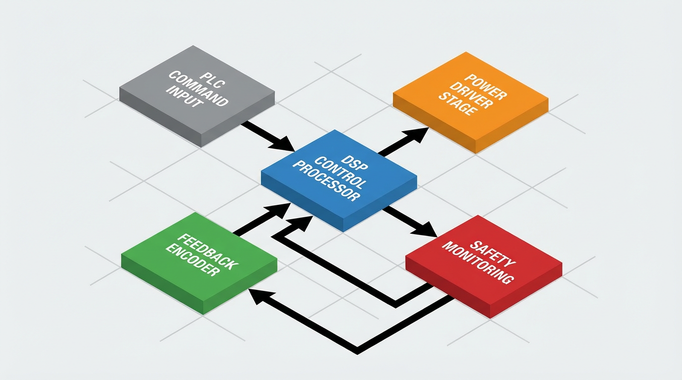
From ITG Motor’s description, typical hardware blocks in a linear motor drive controller include a stable power supply, the power driver, a feedback system, the control processor itself, industrial communication interfaces such as EtherCAT, CANopen, or Modbus, and integrated protection mechanisms. Closed‑loop operation based on encoder feedback is essential in high‑precision systems to avoid drift, overshoot, and cumulative error.
From a systems integrator’s perspective, the most important thing to remember is that this controller is not a black box. It is the point where mechanical design, feedback quality, control algorithms, and field realities come together. Neglect any one of these, and high‑speed positioning becomes a source of unpredictable scrap and downtime.
The Demands of High‑Speed Positioning
High‑speed linear axes do not behave like slow screw drives. When you demand rapid accelerations and decelerations while holding microns of accuracy, the dynamics of the entire machine show up in your control problem. A detailed MDPI paper on linear motor feeding systems for CNC machine tools highlights this in several ways.
The paper explains that a linear motor feed system is a strongly coupled electromechanical system. Displacement, speed, and acceleration of the axis affect both the mechanical structure and the servo drive, while changes in servo output force feed back into the mechanics. Because the mover is rigidly connected to the workbench with no intermediate transmission, cutting forces and thrust harmonics act directly on the motor. This increases sensitivity to external disturbances and makes the system more vulnerable to heat, friction, and load imbalances.
The MDPI work notes that as feed speeds increase, thrust harmonics can cause significant displacement fluctuations.
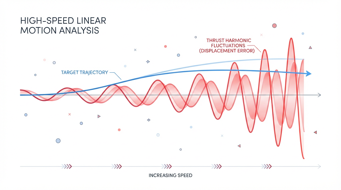
One study they discuss shows that a comprehensive thrust harmonic compensation method reduced displacement fluctuation by more than 90 percent at higher feed speeds. That gives a sense of how large the errors can be if you do not address electromechanical coupling and disturbance effects.
The same paper also emphasizes that flexible deformation of key components such as the workbench and linear guides cannot be ignored at high speeds. Traditional rigid‑body assumptions lead to significant modeling errors, especially when you chase high dynamic performance on an X‑Y linked system.
From the control side, CSK Motion’s overview of linear motor control methods notes that these systems are nonlinear and time‑varying, particularly under changing loads and environmental conditions. That makes classical PID design more challenging, because the optimal parameters can shift across the operating envelope.
In short, high‑speed positioning with linear motors is not just “faster motion.” It is motion where the coupling between control loop, structure, and process forces is strong enough that the system must be treated as a complete electromechanical assembly, not a motor bolted to a frame.
Control Strategies for Linear Motor Drives
PID: The Industrial Workhorse
Despite the complexity of linear motor systems, both the MDPI paper and CSK Motion’s control methods article agree that PID control remains the primary strategy in industrial servo drives. In a typical implementation, there are nested loops: an inner current loop, a middle speed loop, and an outer position loop. Each loop uses proportional, integral, and sometimes derivative terms to regulate its variable.
PID’s strengths are well known. It is conceptually simple, highly familiar to plant engineers, and robust when the system behaves approximately linearly within the tuned operating region. For many CNC machines and automation systems, properly tuned PID loops deliver the required accuracy and response.
However, MDPI emphasizes that linear motor feed systems are time‑varying and nonlinear, which makes it difficult to select PID parameters directly. The dynamic and static responses, as well as servo stiffness and disturbance rejection, depend heavily on those parameters. Traditional tuning approaches, such as sequentially pushing bandwidth from inner to outer loops, require repeated frequency‑response measurements and may ignore interactions between loops, making it hard to find a globally optimal set of gains.
Beyond PID: Fuzzy, Sliding Mode, and Adaptive Control
CSK Motion discusses several modern control strategies for linear motors:
Fuzzy control uses fuzzy logic to handle qualitative descriptions such as “large” or “small” error instead of exact mathematical models. This yields strong adaptability to complex, uncertain, and nonlinear systems. The tradeoff is that it relies heavily on expert‑designed rules and can be time‑consuming to debug.
Sliding mode control defines a sliding surface and a switching law that drives the system state onto that surface and keeps it there. It offers high robustness against parameter uncertainties and external disturbances, making it attractive for high‑precision control. Its weakness is chattering, the high‑frequency switching that can induce mechanical and electromagnetic noise if not managed carefully.
Adaptive control incorporates a mechanism that continuously adjusts controller parameters based on real‑time performance measurements. It is designed for systems with uncertain or changing parameters. The advantage is automatic accommodation of variations; the cost is higher design complexity and computational load.
CSK Motion also notes that neural network and model predictive control are gaining ground as computation and development tools improve. These can further enhance accuracy and disturbance rejection when properly applied.
In practice, most commercial linear motor drives expose a PID‑like interface and may embed more advanced strategies internally. From the outside, as the integrator, your job is to specify a controller with the feedback quality, loop bandwidth, and tuning tools that match your application, rather than chasing exotic algorithms for their own sake.
Optimization: Genetic Algorithms and Rigid–Flexible Modeling
The MDPI paper provides a useful example of how advanced modeling and optimization techniques can help when basic tuning is no longer sufficient. The authors build a rigid–flexible electromechanical coupling model that combines multibody rigid dynamics, finite element modeling of flexible components, and an analytical representation of the permanent magnet linear motor. To optimize the control, they apply an improved genetic algorithm with nonlinearly varying crossover and mutation probabilities.
This algorithm jointly optimizes the PID parameters of the position, speed, and current loops in the rigid–flexible model. The result, according to the paper, is improved motion accuracy, dynamic characteristics, and disturbance rejection for an X‑Y linear motor feeding system.
Few factories are going to run genetic algorithms on their production drives.

The point is that for very demanding applications with high speeds and tight tolerances, especially on multi‑axis systems, you may need to treat tuning as an optimization problem at the system level, not a knob‑twisting exercise on a single axis.
Integrated “Smart” Linear Motors vs Traditional Architectures
There are two broad ways to build a linear axis: the traditional modular route with a separate drive and controller, or a fully integrated “smart” linear motor. White papers from Iris Dynamics and an explanatory article on smart linear motors provide a clear picture of the tradeoffs.
Traditional Controller plus Linear Motor
In the modular architecture, you have a separate linear motor, external position sensors, a separate servo drive, a controller, and cabling tying it all together. ITG Motor’s description of controllers fits this architecture: the drive handles power and current control, the controller runs motion profiles and multi‑axis coordination, and encoders or resolvers provide feedback.
This setup maximizes flexibility. You can choose any combination of motor, encoder, and drive that meets your requirements, swap components as vendors evolve, and integrate deeply into a plant‑wide control system. It also maximizes integration work, wiring complexity, and potential failure points.
Fully Integrated Smart Linear Motors
Iris Dynamics describes a different approach: the fully integrated linear motor. Their ORCA series motors contain the motor, driver, controller, and an array of sensors for force, position, and temperature within a single sealed unit. Power comes in through one DC connection, and the motor handles internal control loops on its own.
Because the sensors and electronics are designed and calibrated together, Iris reports sub‑millisecond closed‑loop response and low‑latency control suitable for high‑bandwidth actuation and high‑fidelity haptic effects. The motors are epoxy‑potted and sealed to IP68, with a single moving stainless steel shaft. That design reduces mechanical complexity and failure points. Maintenance is largely limited to bushings, which they note cost about $2 per set and can last over one million cycles under ideal conditions.
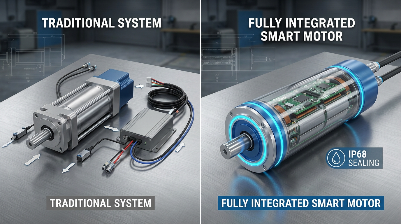
Data logging is built in, tracking variables such as force, position, speed, temperature, power, and voltage. This makes predictive maintenance straightforward. The ORCA series supports common software interfaces including Python, C++, Modbus RTU, MATLAB, LabVIEW, and PWM modules. From a project perspective, that reduces the need for deep motion‑control expertise in the integration team.
The “smart linear motors explained” article expands on this concept. It defines a smart linear motor as a linear motor with integrated sensing, onboard logic, and a communication language. Embedded sensors measure force, position, speed, acceleration, temperature, and voltage, all protected inside the motor body. Consolidating sensing into the motor drastically reduces cabling to PLC cabinets and improves noise immunity, particularly in factory environments.
Smart motors can locally handle force control, position control via PID‑type loops, path planning for smooth motion profiles, and haptic effects such as springs, dampers, inertia, and vibrations. They typically communicate via serial protocols or analog schemes such as 4–20 mA, and often ship with software development kits so programmers can work at the application level.
The same article notes limitations. Because motion is direct and there is no mechanical self‑locking, smart linear motors move freely when unpowered and rely on active control loops to provide stiffness. They must draw power continuously to hold loads against gravity or other steady forces. As a result, they cannot match the passive rigidity and fail‑safe behavior of screw drives or hydraulics in some heavy, static load cases.
Architectural Comparison
The differences can be summarized concisely.
| Aspect | Traditional controller + linear motor | Fully integrated smart linear motor |
|---|---|---|
| Components | Separate motor, drive, sensors, controller, external cabling | Motor, drive, sensors, and logic in one sealed unit |
| Integration effort | Higher: sourcing, wiring, calibration, compatibility checks | Lower: plug‑and‑play, pre‑calibrated, one DC supply |
| Flexibility | Very high; mix‑and‑match vendors and components | Lower; tied to vendor’s mechanical and electrical envelope |
| Performance tuning | More manual setup and tuning required | Many loops pre‑tuned; exposes higher‑level commands |
| Reliability points | Multiple connectors, cables, exposed electronics | Single moving part, minimal wiring, IP68 sealing (in ORCA case) |
| Maintenance | Distributed across drives, cables, sensors, mechanics | Primarily bushings and external guides; electronics largely sealed |
For fast positioning in compact equipment, integrated motors can collapse development time from days to minutes. For larger multi‑axis systems with demanding synchronization, or where plant standards dictate specific drives and networks, the traditional architecture remains the default.
Linear Motors vs Ball Screw and Stepper‑Based Stages
Before committing to a linear motor controller, you should be confident that direct‑drive technology is the right fit for the axis.
A technical article from Helix Linear describes ball screw linear actuators as mechanical devices that convert motor rotation into linear motion using a screw and recirculating ball bearings. They deliver high precision and repeatability, high power transmission efficiency, and smooth, quiet motion. Engineers select them based on load, required speed, accuracy, backlash, and environmental factors such as temperature and contamination, often adding seals, lubrication, or coatings for durability.
CSK Motion’s piece on optimizing stepper motor linear motion explains how discrete electrical pulses drive stepper motors in fixed angles, for example 1.8 degrees per step or 200 steps per revolution. Microstepping can subdivide these steps for smoother motion. Stepper‑driven linear stages can be effective and cost‑efficient, especially when coupled with ball screws or belts, but they require careful consideration of control strategy, drive electronics, mechanical transmission, and load management. The article notes that open‑loop stepper systems are simple and low cost but prone to missed steps under changing loads, whereas closed‑loop stepper drives add feedback and complexity but greatly improve accuracy and robustness.
A broader motor selection guide in Tech Briefs emphasizes starting from application requirements, not from motor type. It recommends sizing from the load and motion profile, checking bus voltage, and considering environment and in‑house expertise. For stepper motors, the guidance is to operate conservatively, roughly at half their maximum torque and speed to avoid lost steps, whereas servo systems with feedback can run closer to their limits.
HEIDENHAIN’s linear motor brochure and related application notes from companies such as Aerotech highlight the advantages of linear motors over screw or belt drives when you need very high dynamics, very high speed, and low maintenance. With no mechanical transmission, there is no backlash and much less wear. Combined with high‑resolution encoders, this allows micrometer or even sub‑micrometer positioning accuracy over long travels.
The tradeoffs are also clear in those documents. Linear motors have higher upfront cost, strong magnetic attraction forces that require robust mechanics and safety measures, and more stringent thermal management. Continuous force is limited by allowable winding temperature, often on the order of roughly 175 to 210 degrees Fahrenheit at the winding, so RMS current must be managed carefully.
In practical terms, if your axis must run at high speed, with frequent accelerations and decelerations, tight tolerances, and low maintenance, linear motors with proper controllers are often the right choice.
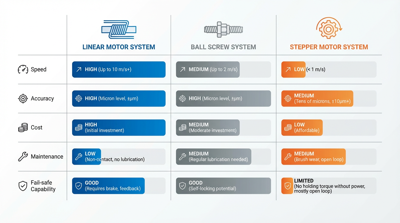
If the axis is slower, carries very heavy static loads, or must hold position without power for safety reasons, a ball screw or similar mechanical actuator may still be preferable.
Practical Design and Commissioning Guidance
Start with Motion and System Requirements
The Tech Briefs guidance is blunt: do not start with the motor or controller catalog. Start with the loads on all axes, the desired motion profile, the required positioning accuracy, and the available bus voltage. If the required speed and cycle time exceed what the supply voltage can support, you will need a different winding or even a different architecture.
For linear motor controllers, ITG Motor recommends selecting drives with robust closed‑loop feedback, advanced algorithms such as PID with trajectory planning, suitable communication interfaces for your plant network, and integrated safety features. The article also stresses the value of real‑time monitoring and diagnostics of position, velocity, current, temperature, and error states to support predictive maintenance and reduce downtime.
An article on linear automation upgrades in SVI News points out that modern motion controllers and high‑resolution encoders can compensate for mechanical imperfections and load variations, reducing positioning errors and stabilizing performance under changing conditions. It also notes that absolute encoders, which preserve position through power loss, can eliminate homing moves and speed up reliable restarts.
From a systems integrator’s perspective, it is worth formalizing these requirements upfront. Document the load, travel, accuracy, ambient environment, and control integration constraints before you touch a controller configuration file.
Pay Attention to Feedback and Trajectory Planning
For high‑speed axes, feedback and motion profiles matter as much as the motor itself. ITG Motor highlights the importance of encoders or resolvers that provide fine‑grained measurements of position, speed, and acceleration. SVI News emphasizes that high‑resolution and absolute encoders allow finer corrections and avoid recovery errors after power interruptions.
A detailed discussion on Robotics Stack Exchange about controlling both position and velocity of a linear actuator illustrates the logic many engineers implement in practice. Rather than stepping directly from one position to another, they generate motion profiles such as trapezoidal or S‑curve velocity trajectories. These profiles ramp acceleration, hold a constant speed, and then decelerate smoothly, reducing jerk and mechanical shock while hitting final positions accurately.
In microcontroller‑based implementations, the profile is often computed on the fly rather than stored as a long table, due to memory constraints. Even in industrial controllers, the principle is the same: you want the drive to generate jerk‑limited trajectories internally or accept pre‑computed profiles that avoid exciting structural resonances.
If your candidate controller cannot support jerk‑limited profiling or at least flexible acceleration and deceleration control, you are going to struggle with vibration and settling time at high speed.
Commissioning: Cabling, Commutation, and Safety
Kollmorgen’s practical guide to setting up linear motor systems reads like a checklist of things that go wrong during commissioning. Because the stator is stationary and the coil or slider moves, cables must move with the axis. The guide stresses the use of sufficiently flexible cables, respecting minimum bend radius, and using proper grounding and shielding.
Before first power‑up, the recommendation is to verify all wiring, reduce the drive’s peak current to safe levels, and provide physical stops at both ends of travel, for example wooden blocks. This provides a mechanical safety net if commutation or feedback configuration is incorrect and the axis attempts to run away.
The same guide notes that servo drives must be configured with accurate motor parameters to achieve correct commutation and initial loop tuning.
For their AKD series, many parameters can auto‑populate when the right motor model is selected, but feedback resolution, encoder direction, motor phase sequence, and Hall sensor sequence still must be confirmed. Tools in the drive configuration environment assist with verifying feedback resolution and testing commutation direction before free motion is allowed.
Once commutation is verified, the recommended practice is to exercise the axis with short, controlled moves back and forth, still with limited peak current, before opening up the full travel. This is a habit worth preserving across all linear motor platforms.
On the low‑level control side, a linear actuator thread on the Arduino Forum provides a small but important lesson: keep interrupt service routines short. The author initially placed serial printing and timing functions inside the interrupt that counted hall sensor pulses, which broke communication because those functions rely on interrupts themselves. After removing serial calls and unnecessary timing from the interrupt, and verifying the sensor signal with an oscilloscope to confirm no debouncing was needed, the position counting became reliable. Even though industrial drives hide these details inside firmware, the principle stands: keep the fast feedback path lean and avoid heavy operations where timing must be deterministic.
Monitoring, Diagnostics, and Maintenance
Integrated sensing and logging are not marketing luxuries; they are how you keep high‑speed axes reliable over years of operation.
Iris Dynamics points out that their fully integrated motors log force, position, speed, temperature, power, and voltage continuously. This enables predictive maintenance based on real usage rather than calendar time. The same article notes that with IP68 sealing and epoxy potting, the only scheduled wear items are bushings, which cost a few dollars per set and can last more than a million cycles under favorable conditions.
The smart linear motors article corroborates the benefits of embedding sensors inside the motor and consolidating them on a printed circuit board. This reduces external cabling and improves survivability against vibration, dust, and moisture.
SVI News extends this argument to plant‑wide linear automation. Smart sensors monitoring vibration, temperature, and other parameters enable condition‑based maintenance that can forecast failures, prevent unexpected stoppages, and reduce emergency repairs. The article highlights automated lubrication systems and proper cable management with energy chains as key contributions to reliability in moving axes.
Carpenter Electrification, in its discussion of linear motor performance, adds a materials perspective. By using soft magnetic alloys such as Hiperco 50 in motor cores, manufacturers can achieve up to about 25 percent higher saturation induction, roughly four times higher permeability, and around 30 percent lower core losses compared to conventional electrical steels. This leads to more powerful and efficient motors that can be made smaller, leaving more space for cooling and other equipment. Combined with advanced feedback and control, this supports sustained high performance in demanding environments.
If your application is critical enough to justify a linear motor, it is critical enough to justify instrumenting and monitoring the axis properly. Choose controllers and motors that expose diagnostic data, and plan from day one to use it for predictive maintenance.
Risks, Tradeoffs, and Common Failure Modes
The brochures and application guides from HEIDENHAIN, Aerotech, and others are clear that linear motors are not universal solutions.
Strong magnetic attraction forces in iron‑core designs can be several times the continuous thrust rating. If the guideway or structure is insufficiently stiff, these forces can deform mechanics, degrade accuracy, and increase wear. Mechanical design must therefore accommodate not only the dynamic thrust but also static magnetic forces with appropriate safety margins.
Thermal management is another recurring theme. Continuous force is limited by winding temperature; over‑ambitious tuning that demands too much continuous current will push temperatures beyond acceptable ranges. This can damage insulation, weaken magnets, and reduce lifetime. Managing RMS current, providing adequate heat sinking or forced cooling, and verifying operating temperatures under worst‑case duty cycles are essential tasks.
Smart linear motors have their own limitations, as the explanatory article points out. Because there is no mechanical self‑locking, they require continuous power and active control to hold loads against gravity or other steady forces. If your risk assessment requires the axis to stay in place without power, you must add mechanical brakes, counterbalance mechanisms, or choose a different actuator technology.
Finally, several sources, including the CSK Motion and SVI News articles, note that integration difficulty and higher initial cost remain barriers in some retrofit scenarios. Careful planning and, in many cases, consultation with experienced vendors or integrators are needed to ensure that the benefits of linear motors outweigh the added complexity.
Short FAQ
Do I always need advanced control methods like sliding mode or model predictive control for linear motor drives?
No. Both the MDPI study on linear motor feeding systems and CSK Motion’s control overview make it clear that well‑implemented PID control remains the standard in industrial practice. For many high‑speed positioning tasks, nested PID loops for current, speed, and position, combined with good feedback and motion profiling, deliver the required performance. Advanced methods such as fuzzy control, sliding mode, adaptive control, or neural network‑based strategies become attractive when the system is highly nonlinear, parameters vary significantly over time, or disturbance rejection requirements exceed what conventional tuning can provide. Even then, these methods are typically embedded inside specialized controllers rather than implemented from scratch on the plant floor.
When is a ball screw or stepper‑based system still the better choice than a linear motor?
The Helix Linear article on ball screw actuators and CSK Motion’s discussion of stepper‑driven linear motion highlight several cases where mechanical transmission plus a rotary motor is still preferable. If the axis is relatively slow, carries heavy static loads, must hold position without continuous power, or has modest accuracy requirements, a ball screw with a servo or stepper can be simpler, cheaper, and easier to make fail‑safe. Tech Briefs also notes that stepper systems, especially with modern feedback, can deliver respectable accuracy at lower cost in suitable operating ranges. Linear motors earn their keep when you truly need very high speed, very fast accelerations, minimal maintenance, and tight tolerances over long service life.
What is the most common mistake you see when commissioning linear motor controllers?
The recurring problems in both the Kollmorgen setup guide and community sources such as the Arduino Forum thread fall into two categories. The first is configuration and wiring mistakes: mis‑phased motors, incorrect feedback resolution or direction, and inadequate cable management. These show up as axes that try to run away, fault immediately, or exhibit unstable motion. The second is overloading the fast control path with unnecessary work, whether that is heavy code inside interrupts in embedded systems or overly aggressive filtering and data logging inside drive loops. The antidote is methodical setup: verify wiring and feedback, limit current, use physical stops during initial tests, keep the real‑time control loop lean, and only then push dynamic performance.
When you treat a linear motor drive controller as a component in isolation, you get surprises on the factory floor. When you treat it as part of a tightly coupled electromechanical system, size and tune it accordingly, and use the diagnostic capabilities that modern drives and smart linear motors offer, you get axes that hit their marks at full speed and keep doing so for years. That is the difference between a flashy technology demo and a production‑grade motion system you can confidently sign your name under.
References
- https://en.wikipedia.org/wiki/Linear_motor
- https://ieeexplore.ieee.org/document/1210673/
- https://www.carpenterelectrification.com/blog/linear-motor-performance
- https://resources.helixlinear.com/blog/optimizing-precision-and-efficiency-with-ball-screw-linear-actuators
- https://irisdynamics.com/articles/fully-integrated-linear-motors-saving-engineers-dev-time-and-money
- https://itg-motor.com/how-linear-motor-controllers-work-key-components-and-functions/
- https://www.ai-futureschool.com/en/electrotechnics/understanding-linear-motors-and-their-operating-principles.php
- https://forum.arduino.cc/t/linear-actuator-position-control/223814
- https://www.cskmotions.com/blogs/news/introduction-to-linear-motor-control-methods
- https://www.kollmorgen.com/en-us/blogs/tips-on-how-to-confidently-set-up-your-linear-motor-system
Keep your system in play!
Top Media Coverage
Categories


Related articles Browse All
-
 amikong NewsSchneider Electric HMIGTO5310: A Powerful Touchscreen Panel for Industrial Automation2025-08-11 16:24:25Overview of the Schneider Electric HMIGTO5310 The Schneider Electric HMIGTO5310 is a high-performance Magelis GTO touchscreen panel designed for industrial automation and infrastructure applications. With a 10.4" TFT LCD display and 640 x 480 VGA resolution, this HMI delivers crisp, clear visu...
 -
 BlogImplementing Vision Systems for Industrial Robots: Enhancing Precision and Automation2025-08-12 11:26:54Industrial robots gain powerful new abilities through vision systems. These systems give robots the sense of sight, so they can understand and react to what is around them. So, robots can perform complex tasks with greater accuracy and flexibility. Automation in manufacturing reaches a new level of ...
 -
 BlogOptimizing PM Schedules Data-Driven Approaches to Preventative Maintenance2025-08-21 18:08:33Moving away from fixed maintenance schedules is a significant operational shift. Companies now use data to guide their maintenance efforts. This change leads to greater efficiency and equipment reliability. The goal is to perform the right task at the right time, based on real information, not just ...


- Q&A
- Policies How to order Part status information Shipping Method Return Policy Warranty Policy Payment Terms
- Asset Recovery
- We Buy Your Equipment. Industry Cases Amikong News Technical Resources Why choose us
- ADDRESS
-
 32D UNITS,GUOMAO BUILDING,NO 388 HUBIN SOUTH ROAD,SIMING DISTRICT,XIAMEN
Leave Your Comment