
-
Please try to be as accurate as possible with your search.
-
We can quote you on 1000s of specialist parts, even if they are not listed on our website.
-
We can't find any results for “”.
Modbus RTU Communication Modules: A Veteran Integrator’s Guide to Serial Device Integration
Modbus RTU over RS485 is one of those technologies that quietly refuses to retire. In plants where I have had to integrate drives, meters, and remote I/O built twenty years apart, a solid Modbus RTU communication module has been the simplest way to get everything talking without ripping out existing wiring. If you work in industrial automation and control hardware, understanding how to design, deploy, and troubleshoot these modules is still a core skill.
This article walks through Modbus RTU communication modules from a systems integrator’s point of view: what they do, how the protocol actually works on the wire, how to design a reliable RS485 network around them, how to integrate legacy serial devices into modern architectures, and how to avoid the classic traps that keep support desks busy. The guidance here draws on field experience as well as references like Maple Systems’ Modbus protocol guide, Moore Industries’ process control notes, Redz and Wevolver’s Modbus RTU explainers, RealPars’ protocol comparisons for oil and gas, and troubleshooting best practices documented by AutomationForum and RTA Automation.
Why Modbus RTU Still Matters On The Plant Floor
Modbus was introduced by Modicon, now Schneider Electric, in the late 1970s as an open, royalty‑free protocol for PLCs and field devices. Maple Systems and others point out that this openness is why Modbus became a de facto standard across HMIs, PLCs, remote I/O, smart sensors, and drives. There is no vendor lock‑in at the protocol level, and you can still mix devices that were designed decades apart.
Modbus RTU is the compact binary serial flavor of Modbus. Redz, Wevolver, and Moore Industries all describe the same basic pattern: a master–slave or client–server architecture over RS232, RS422, or most commonly RS485, with messages framed as binary bytes plus a CRC checksum. RS485’s differential signaling and noise immunity make it well suited for the electrically harsh environments you see near VFDs, motors, and long cable runs. RTA Automation emphasizes that Modbus RTU over RS485 remains widely deployed today precisely because it is inexpensive and resilient in EMI‑heavy locations like refineries, water treatment plants, and remote pumping stations.
In practical terms, Modbus RTU remains the easiest way to integrate a wide range of serial devices: drives, power meters, RTUs, HVAC controllers, and specialty analyzers. RealPars notes that in oil and gas, Modbus is still a workhorse between RTUs, PLCs, SCADA systems, and analyzers, favored for its low cost and ubiquity. Redz adds similar examples from manufacturing automation, building management, and energy systems.
The downside is also well documented. Maple Systems and Redz both highlight that classic Modbus RTU is slower and less scalable than Ethernet‑based protocols and offers no built‑in cybersecurity. RealPars is explicit that Modbus, especially serial Modbus, is normally confined to isolated networks without external access for this reason. That is where Modbus RTU communication modules and gateways come in: they let you keep the robust RS485 segment while bridging up into IP, SCADA, or IIoT layers that add security, analytics, and remote access.
What A Modbus RTU Communication Module Actually Does
In most architectures I work on, a Modbus RTU communication module is the boundary between the RS485 field bus and the main controller, HMI, or supervisory system. Sometimes it is a plug‑in card in a PLC rack, sometimes it is a DIN‑rail gateway, and sometimes it is part of a supervision platform with multiple RS485 ports, like the HSYCO controllers described in HSYCO’s Modbus RTU supervision guide.
Conceptually, the module sits in one of two roles. In many projects the module is the Modbus master on the RS485 trunk, polling multiple slave devices, collecting data, and presenting that data upstream as internal tags, OPC UA items, Modbus TCP registers, or another protocol. This is the model you see in FlowFuse’s Node‑RED example, where FlowFuse acts as Modbus RTU master, continuously reading coils and registers from devices with slave IDs from 1 to 247.
In other projects the module presents itself as a Modbus RTU slave to a controller while acting as a master on one or more downstream serial segments. That pattern is common in remote I/O stations or small RTUs. DPSTele’s Modbus best practices article adds another variant: a Modbus bridge that appears as a Modbus TCP device on the Ethernet side and translates those requests into serial Modbus RTU on the RS485 side. The master on Ethernet does not need to know that the end devices are serial; it simply talks to the bridge on port 502, while the bridge handles RTU timing, addressing, and CRC.
In every case, the communication module’s value is the same. It isolates the messy realities of an RS485 fieldbus—noise, reflections, biasing, odd register maps, slow devices—from the rest of the control system. When the module is configured correctly and the RS485 segment is sound, the rest of the system can treat those serial devices as just another set of structured data points.
Core Modbus RTU Concepts Every Module User Must Understand
Before choosing or configuring a Modbus RTU communication module, it is worth revisiting how Modbus RTU actually works on the wire. The module cannot hide protocol mistakes.
Frame Structure, CRC, And Exceptions
Wevolver and Maple Systems both describe the same RTU frame structure. Each request or response contains a one‑byte slave address, a one‑byte function code, a variable‑length data field, and a two‑byte CRC‑16 checksum. The CRC covers the entire frame; the receiver recomputes it and rejects the message if it does not match. AutomationForum’s troubleshooting guide notes that when devices detect data integrity problems, they may signal this using exception code 08, labeled Memory Parity Error, which is effectively an indicator of corruption or parity issues.
Modbus RTU slaves do not silently ignore valid but unserviceable requests. AutomationForum summarizes how they generate exception responses: the slave echoes the original function code but with the highest bit set and appends an exception code. For example, a request using function code 01 (read coils) would produce a response with function code 81 plus a specific exception code if the request cannot be processed. Exception code 02, Illegal Data Address, is common when a master tries to read a coil or register address that is not defined in the device’s Modbus map.
Other exception codes described in that same reference include Illegal Function, Illegal Data Value, Slave Device Failure, Acknowledge, Slave Device Busy, Negative Acknowledge, Gateway Path Unavailable, and Gateway Target Device Failed to Respond. A good RTU communication module should expose these exceptions in logs or diagnostics so engineers can distinguish protocol problems from wiring faults.
Master–Slave Model And Addressing
All of the serial‑focused sources reinforce the same architecture. Modbus RTU uses a single master on the serial bus, while each slave responds only when addressed. Maple Systems describes this as a master–slave model; DEOS notes the same pattern, calling the controlling node the master in RTU and the client in Modbus TCP. AutomationForum explicitly recommends respecting the single‑master principle for Modbus RTU to avoid collisions.
Each device on a serial Modbus network has a unique numeric address, typically in the range 1 to 247. Maple Systems and Wevolver both call out that range; FlowFuse’s example also uses 1 to 247 and notes that 0 is reserved for broadcast. HSYCO’s guide warns that although 247 addresses exist in theory, you should not plan to populate them all on one RS485 line. They recommend limiting to about 32 devices per segment to avoid bus loading and signal quality problems, which aligns with Moore Industries and RTA Automation’s references to the standard 32‑device limit per RS485 segment.
A Modbus RTU communication module must honor these constraints. If it is acting as the master, it can only poll one slave at a time. If it is acting as a slave, it must have a unique address and it must not respond to broadcast messages except as defined by the protocol and the upstream controller’s expectations.
Coils, Registers, And Addressing Pitfalls
A large part of successfully integrating serial devices lies not in the wiring but in the register map. Maple Systems, FlowFuse, Teracom Systems, and Wevolver all explain the same four logical Modbus data types: coils, discrete inputs, input registers, and holding registers.
Coils are single‑bit, read/write values typically representing digital outputs or control points. Discrete inputs are single‑bit, read‑only values representing digital inputs or status contacts. Input registers are read‑only 16‑bit values often used for analog measurements or calculated values. Holding registers are read/write 16‑bit values for parameters, setpoints, and analog outputs. Maple Systems notes that each of these types has its own logical address space, often referenced as 0x, 1x, 3x, and 4x ranges.
The complications start with addressing notation. FlowFuse and Teracom highlight that many device manuals use one‑based logical addresses like 40001 for holding registers, while the actual on‑wire addresses in Modbus RTU are zero‑based. FlowFuse gives a simple case where a manual lists an item as 40001, but the master must actually request address 0 when building the Modbus RTU frame. Teracom goes further, explaining that vendors use different offsets like 40001, 400001, or other bases, but the protocol data unit on the wire always references a 0 to 65,535 address space. Logical address 40014 in one manual and 400014 in another might both map to the same underlying PDU address once you subtract the vendor‑specific offset.
For a communication module, this has two immediate implications. First, its configuration interface must allow you to specify the correct zero‑based address even when the device manual uses one‑based or 4xxxx formats. Second, your team must treat the official register map as the source of truth and reconcile it carefully with the module’s addressing model. FlowFuse explicitly recommends always keeping the device’s register map at hand for this reason, and Teracom’s guidance is essentially the same: identify the vendor’s offset and convert correctly between logical and PDU addresses to avoid reading the wrong data.
Designing A Reliable RS485 Network Around The Module
The reliability of a Modbus RTU communication module is bounded by the quality of the RS485 network it connects to. Several references converge on the same physical‑layer best practices: use RS485 where multi‑drop and long distances are required, follow the right topology, use proper cabling, and apply termination and biasing correctly.
RS232 Versus RS485 In The Real World
Redz, HSYCO, and Wevolver all compare RS232 and RS485. RS232 is single‑ended and point‑to‑point, typically limited to short distances of roughly 50 ft and a single device pair. That makes it acceptable for a single panel connection but rarely for a plant‑wide bus.
RS485, by contrast, uses differential signaling, supports multi‑drop bus topologies, and can support cable runs on the order of 4,000 ft at moderate baud rates according to HSYCO and Moore Industries. RTA’s RS485 overview cites the same distance scale and notes the standard limit of 32 devices per segment. This is why RS485 is the dominant physical layer for Modbus RTU modules in industrial environments.
Topology, Cabling, And Separation From Power
Both HSYCO and AutomationForum stress that an RS485 network should be a linear bus, not a star. Devices should be connected in a daisy‑chain along the main trunk; long stubs and star branches introduce reflections that distort signals and cause intermittent communication failures. HSYCO suggests that any unavoidable star connections be kept very short and lightly loaded.
For cabling, the shared guidance across HSYCO, AutomationForum, TrackSo’s cabling note, and the Trend BMS engineer’s RS485 guidance is consistent. Use twisted‑pair cabling for the RS485 differential pair, and shielded twisted pair in noisy environments. HSYCO mentions standard twisted‑pair categories like CAT5E. AutomationForum calls out shielded twisted pair as an advanced best practice to reduce electromagnetic interference and preserve signal integrity over long distances. The Trend BMS advice adds a pragmatic detail: run three conductors, positive, negative, and a reference, and ground the cable shield correctly.
A simple but critical rule appears in TrackSo’s RS485 cabling guidance and in the building‑automation comment from the Trend BMS group: do not run RS485 communication cables bundled with mains power conductors. High voltages and currents on mains wiring can induce noise into the low‑voltage RS485 cable, and in the event of faults or arcing on the mains, dangerous voltages can be imposed on the communication cable. The consistent recommendation is to route RS485 physically away from power cables, using separate conduits or cable trays where practical.
Termination, Biasing, And Grounding
Proper termination and biasing distinguish a stable RS485 network from one that only works on the bench. HSYCO and AutomationForum recommend installing a termination resistor of roughly 120 ohms at the end of the RS485 line on the last device, and often one near the first device as well, with care taken to avoid excessive parallel terminations. AutomationForum also calls out biasing resistors, around the same order of magnitude, to hold the lines in a known idle state and prevent random noise from being interpreted as data.
Moore Industries and RTA Automation extend the physical‑layer recommendations to grounding and isolation. HSYCO suggests grounding the cable shield at only one end to minimize ground loops. RTA talks about using careful grounding and isolated transceivers to mitigate ground potential differences between panels or drive systems. In practice, that means you should consider whether your Modbus RTU communication module has galvanic isolation on its RS485 ports and plan your grounding so that shield currents do not flow through device reference pins.
Device Count And Segmenting With Multiple Ports
The theoretical Modbus addressing space allows 247 slave IDs, but HSYCO’s guidance to limit a single RS485 segment to about 32 devices is sound. Moore Industries and RTA Automation both reiterate that RS485 was specified for 32 unit loads per segment by default, and while modern low‑load transceivers can stretch that number, bandwidth, polling time, and troubleshooting all become harder as you add devices.
This is where devices with multiple RS485 ports, such as the HSYCO Core and HSYCO Pro platforms described in HSYCO’s documentation, become valuable. HSYCO Pro supports up to eight RS485 ports, which allows large networks to be segmented into smaller, independent buses. A Modbus RTU communication module with multiple ports can serve a similar purpose: separate high‑chatter loads from slower devices, isolate critical control loops from noncritical metering loads, and contain faults to a single segment.
Configuring The Modbus RTU Module: Parameters And Mapping
Once the physical network is sound, most integration problems reduce to configuration. AutomationForum and Maple Systems are explicit that all devices on a Modbus RTU network must share the same serial settings: baud rate, parity, data bits, and stop bits. FlowFuse, RTA’s troubleshooting article, and many vendor manuals repeat this rule in slightly different words.
A practical sequence that has served me well matches AutomationForum’s step‑by‑step troubleshooting guidance. First, confirm that the module’s serial parameters match the device documentation exactly. Do not assume defaults; check every device. Maple Systems notes that typical Modbus RTU settings are eight data bits, parity enabled, and one stop bit, but you should rely on each device’s manual. Second, start with a moderate baud rate rather than the maximum specified. AutomationForum recommends doing this and only increasing the baud rate after you have stable, error‑free communication. Moore Industries also describes the trade‑off: higher baud rates improve throughput but make long distances and noisy environments more challenging.
Register mapping deserves its own configuration pass. As Moore Industries suggests, you should group frequently used measurements and controls into contiguous blocks of holding registers or coils to minimize the number of separate Modbus transactions. Maple Systems and FlowFuse both emphasize aligning the master’s understanding of register types, addresses, and scaling with the device documentation. Many devices pack 32‑bit values into two consecutive holding registers or use scaling factors (for example an integer value that must be divided by ten or one hundred) to represent engineering values. FlowFuse shows how these conversions can be handled in software once you understand them, and Moore Industries recommends documenting your tag‑to‑register mapping carefully for maintainability.
Finally, remember that a Modbus RTU communication module acts as a master on the RS485 bus and may have its own polling engine. Moore Industries and DPSTele both point out that polling strategies matter. You should design poll rates so that critical registers are read as often as needed, less critical data is grouped into slower scans, and total scan time across all slaves remains acceptable. Over‑aggressive polling simply wastes bandwidth and can aggravate latency.
Integrating Serial Devices Into Modern Architectures
Once a Modbus RTU communication module has a reliable RS485 segment behind it, the next question is how to present that data upward. Different references describe different approaches, but all share the same theme: use the right tool for the right layer.
Bridging Modbus RTU To Modbus TCP
Maple Systems describes Modbus RTU over TCP as encapsulating whole RTU frames inside TCP/IP packets. DPSTele’s Modbus best practices article focuses on this pattern in practical terms, describing a Modbus bridge that converts between Modbus TCP and serial variants like Modbus RTU or ASCII. The Modbus TCP side uses TCP port 502 and IP addressing to reach the bridge; inside the bridge, those requests are translated into serial frames and dispatched to the appropriate slave address on RS232 or RS485.
DPSTele notes that a single bridge can allow thousands of serial slave devices to be accessed through one Ethernet card, with addressing defined by the IP address plus the slave ID. To the Modbus TCP master, the bridge looks like a collection of Modbus TCP devices; to the serial slaves, the bridge is the master. Multiple Modbus TCP masters can even access the same bridge, though response times will grow as more masters issue requests.
From a systems integrator’s point of view, a Modbus RTU communication module with built‑in Modbus TCP support gives you a neat way to bring legacy serial loads into Ethernet‑centric control networks without touching the field wiring. You keep the RS485 reliability and drop‑in compatibility described by RTA, while gaining IP connectivity and easier routing.
Feeding SCADA, IIoT, And OPC UA Layers
FlowFuse’s article on using Modbus RTU with Node‑RED shows another pattern that is increasingly common. A Modbus master instance reads coils and registers from RTU devices via a USB–RS485 adapter or serial module, then publishes those values into a higher‑level environment where dashboards, alarms, and integrations live. The Modbus RTU communication module might expose a serial port directly to such a platform or might be embedded in a device that runs something like Node‑RED.
RealPars’ discussion of industrial protocols in oil and gas describes how Modbus, Profibus, and OPC UA can coexist. Profibus PA and DP provide high‑performance field communication, while OPC UA acts as a secure, platform‑independent protocol for real‑time and historical data up to enterprise and cloud systems. Modbus is used where simplicity and low cost are most important, typically on closed networks.
Putting these threads together, a practical architecture often looks like this. At the bottom, a Modbus RTU communication module concentrates field devices on RS485. Up one layer, a gateway or controller bridges that Modbus RTU data into Modbus TCP, OPC UA, or similar. At the top, SCADA, historians, and analytics systems subscribe to that data. RealPars recommends using Modbus in closed segments for basic reliability, Profibus where richer sensor‑level capability or intrinsic safety is needed, and OPC UA for large‑scale, secure data collection and integration.
Comparing RTU Modules To Ethernet‑First Alternatives
The pros and cons of sticking with Modbus RTU behind a communication module versus going straight to Ethernet‑based protocols can be summarized from RTA Automation, RealPars, Maple Systems, and Redz.
A Modbus RTU module over RS485 excels when you need long cable runs in noisy environments, when budget is tight, and when backward compatibility with existing PLCs, drives, and meters is non‑negotiable. RTA notes that RS485 can run about 4,000 ft per segment with proper design and that it does not require Ethernet switches or complex infrastructure. Maple Systems and Redz point out that Modbus RTU is simple to implement and widely supported, which keeps device and engineering costs down.
Ethernet‑based alternatives such as Modbus TCP/IP, Profinet, and OPC UA bring higher throughput, more flexible topologies, and better native security. Maple Systems and RealPars both describe Modbus TCP/IP as enabling higher speeds and multiple simultaneous connections, while RealPars highlights OPC UA’s built‑in security and richer data modeling. RTA and RealPars recommend these Ethernet‑centric protocols for greenfield facilities with an Ethernet backbone and strong IT/OT convergence requirements.
In practice, many plants end up with both: Modbus RTU over RS485 for brownfield upgrades and hard‑to‑reach locations, bridged into Ethernet and OPC UA for monitoring and integration.
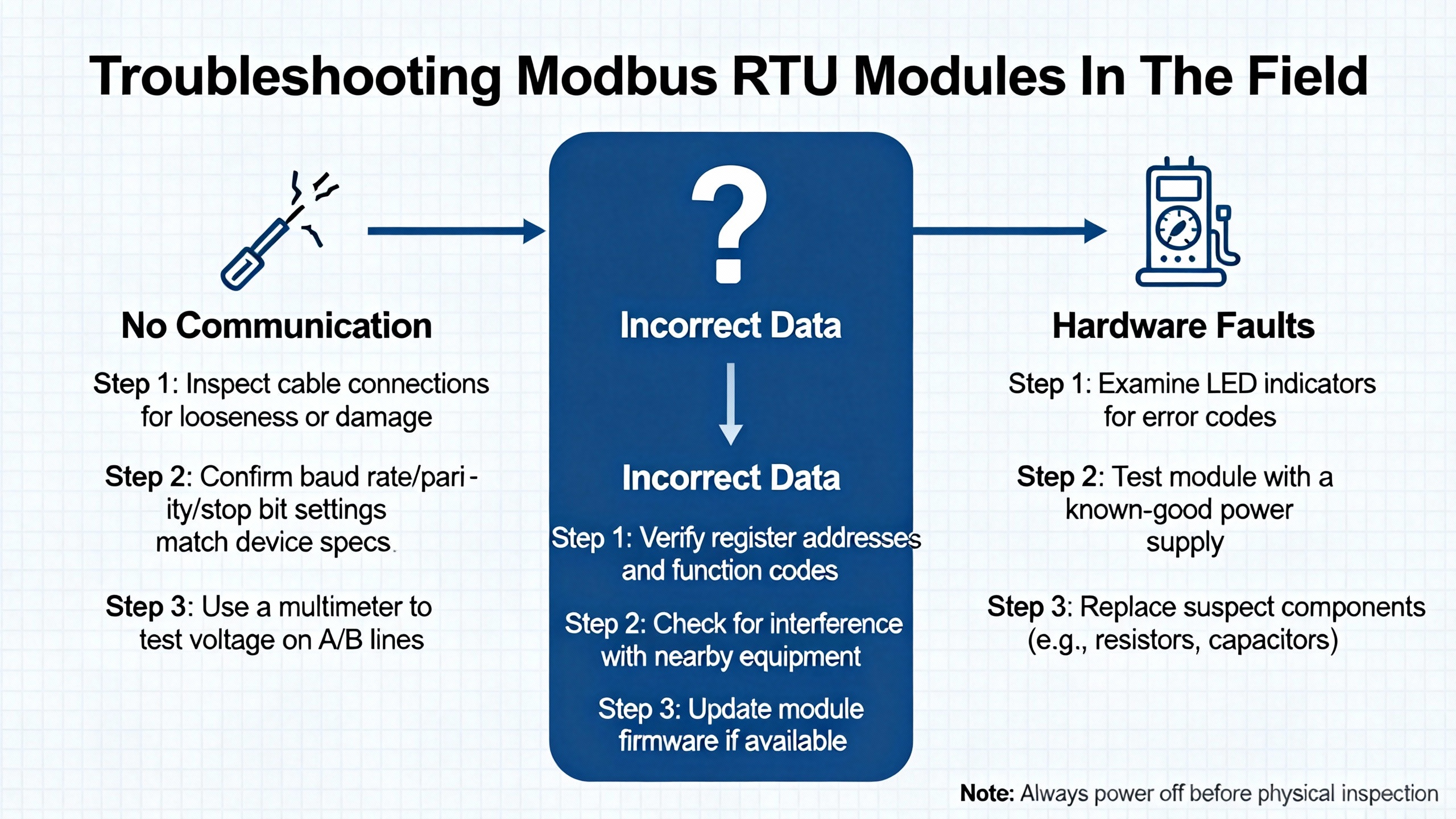
Troubleshooting Modbus RTU Modules In The Field
Most Modbus RTU communication modules are reliable when configured correctly, but real‑world installations still generate many support calls. AutomationForum’s troubleshooting procedure and RTA Automation’s “Wingdings and troubleshooting Modbus comms” article both outline patterns that align well with field experience.
When Slaves Do Not Respond
If your communication module reports timeouts or no response from slaves, start with serial settings. AutomationForum, Maple Systems, FlowFuse, and RTA all stress the importance of matching baud rate, parity, data bits, and stop bits on every device. A single mismatch is enough to prevent responses.
Next, check wiring and polarity. AutomationForum reminds engineers to verify RS485 wiring against the actual network layout, and RTA notes that simply swapping the A and B lines is a very common fix. Ensure that A or plus is connected to A or plus, and B or minus to B or minus, along the entire trunk.
Addressing comes next. HSYCO and Maple Systems both emphasize unique addresses from 1 to 247. RTA recommends physically checking the address displayed on device front panels instead of relying on documentation or assumptions; in practice, it is common to find duplicate slave IDs or units left at factory defaults. Also confirm that the communication module is playing the right role; RTA notes that a PLC configured as a slave when it should be a master will obviously never see responses.
CRC, Memory Parity, And Noise‑Related Errors
When you see CRC errors or exception code 08 (Memory Parity Error), you are dealing with data integrity problems. AutomationForum recommends a structured approach: verify matching communication settings, inspect wiring and grounding, confirm correct addressing, analyze communication logs for patterns, test serial hardware, and consult device documentation.
Physical‑layer noise and reflections are frequent culprits. HSYCO, AutomationForum, and RTA all advocate using shielded twisted‑pair cables, proper termination at the ends of the bus, and biasing resistors to maintain a defined idle state. TrackSo’s guidance and the Trend BMS engineer’s comments reinforce the need to route RS485 away from high‑voltage mains and interference sources and to ground shields correctly. AutomationForum also suggests starting with a moderate baud rate and only increasing it once the network is stable, which is consistent with Moore Industries’ advice about trading bandwidth for reliability.
Illegal Data Address And Other Exceptions
Exception codes like Illegal Data Address and Illegal Function usually indicate configuration or mapping issues rather than wiring problems. AutomationForum’s example of a request to read coil 1186 that returns an Illegal Data Address error is a classic scenario: the master is asking for something that the slave does not implement.
Teracom’s analysis of Modbus RTU addressing shows how easy it is to misalign addresses due to logical numbering schemes. If a device manual lists holding register 40106 with an offset of 40001, the actual PDU address on the wire is 105. If your module is configured to request address 106 because you misinterpreted the offset, you will hit the wrong register or an undefined address. FlowFuse’s explanations of zero‑based versus one‑based addressing and Maple Systems’ emphasis on carefully reading device register tables are in the same vein.
Practical troubleshooting in this area is simple but tedious. Confirm that your module’s function code, register type, and on‑wire address exactly match the device documentation. If an exception persists, review whether the device allows write access to that register or only allows reads; Maple Systems notes that some data types are read‑only by design.
Using PC Tools Alongside Your Module
When things get stubborn, it is often faster to temporarily remove the communication module from the diagnostic loop. AutomationForum mentions Modbus Poll as a useful PC‑based Modbus master with serial traffic monitoring and data logging. RTA recommends Win‑Tech’s ModScan and ModSim, which can turn a PC into a Modbus RTU master or slave or a Modbus TCP client or server. These tools are available in limited free versions, with full versions described as costing under about $100.00 each in RTA’s note.
For accessing RS485 networks from a PC, RTA suggests using a dedicated RS485‑to‑USB converter such as the B+B Smartworx USOPTL4, which they describe as costing around $125.00. While specific models change over time, the principle holds: use a known‑good converter and a clean temporary cable run when verifying device behavior. If the device communicates reliably with a PC tool, the focus shifts back to the communication module and its configuration. If the device fails even in this simple setup, you likely have a device or wiring problem.
IoTRouter’s guide to building a stable Modbus RTU system and ICP DAS USA’s webinar overview on troubleshooting common Modbus issues both underscore another point: logging and systematic diagnostics matter. Configure your communication module to log timeouts, exception codes, and CRC errors where possible, and incorporate periodic status checks so that you see degradation before it becomes a hard failure.
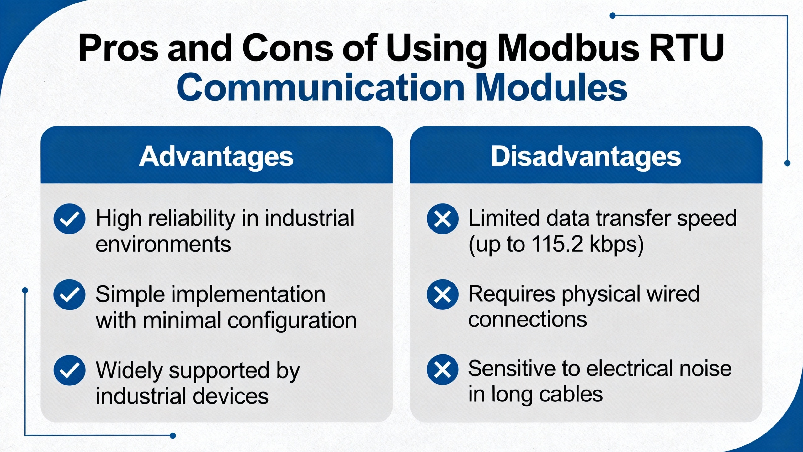
Pros And Cons Of Using Modbus RTU Communication Modules
Bringing these threads together, it is useful to look at the role of Modbus RTU communication modules in a wider protocol landscape, based on the comparisons presented by Maple Systems, RealPars, Redz, RTA, and Moore Industries.
Modbus RTU over RS485, fronted by a communication module, offers simplicity, low cost, and broad device compatibility. It works well over long distances in noisy environments and remains supported by nearly every major PLC, drive, HMI, and field device vendor. It is particularly attractive in brownfield projects where RS485 wiring and serial instruments are already in place. RTA Automation and RealPars both highlight these strengths and note that RS485 is often the only practical choice at remote sites without Ethernet infrastructure.
However, Modbus RTU has inherent limits. Throughput is modest compared with modern Ethernet protocols. Only one master can speak on the serial bus, which constrains how many systems can directly talk to the devices. Maple Systems and RealPars both point out the absence of built‑in security, which is why Modbus RTU networks are usually kept behind other layers and not exposed directly to external networks. Moore Industries notes that Modbus is well suited to supervisory control, monitoring, and data logging, but not to ultra‑high‑speed, safety‑critical control loops that require sub‑millisecond determinism.
Ethernet‑based protocols address some of these gaps. Modbus TCP/IP wraps Modbus into TCP/IP packets, enabling higher speeds and multiple client connections and easy integration into IT networks, as described by Maple Systems and DPSTele. OPC UA adds a richer data model, robust security, and flexible data types at the cost of more complexity and training, according to RealPars. Profibus and Profinet, in the RealPars comparison, deliver high‑performance field communication and, in the case of some Profibus variants, intrinsic safety options for hazardous areas.
In this context, Modbus RTU communication modules are best used as robust edge adapters. They give legacy or remote serial devices a clean interface into IP and higher‑level protocols, leverage RS485’s strengths, and keep the more complex and security‑sensitive parts of the system where they belong: closer to SCADA, historians, and enterprise systems.
Short FAQ
Q: How many Modbus RTU devices should I put behind a single communication module on one RS485 segment? A: The Modbus standard allows 247 addresses, but both HSYCO and Moore Industries recommend limiting a single RS485 line to around 32 devices to avoid bus loading and signal integrity issues. If you need more, use a communication module with multiple RS485 ports or add repeaters and segment the network.
Q: When does Modbus RTU over RS485 make more sense than going straight to Ethernet? A: RTA Automation and RealPars both highlight RS485’s strength for long distances, noisy environments, and budget‑constrained or remote locations without Ethernet infrastructure. In those cases, a Modbus RTU communication module lets you keep the robust RS485 segment while still bridging into Ethernet or OPC UA upstream.
Q: Is Modbus RTU secure enough for remote access over wide‑area networks? A: Maple Systems and RealPars both point out that Modbus, especially serial Modbus RTU, has no built‑in security and is usually confined to closed, isolated networks. For remote access, it is better to keep Modbus RTU behind a communication module or gateway and expose only secured Ethernet protocols such as Modbus TCP/IP with proper network controls or OPC UA, which RealPars describes as having strong security features.
As a systems integrator, I treat a Modbus RTU communication module as a disciplined boundary: on one side, a carefully engineered RS485 bus; on the other, controllers, SCADA, and enterprise systems that expect clean, structured data. If you respect the physical‑layer rules, configure the protocol correctly, and use the module’s diagnostics intelligently, Modbus RTU will continue to be a dependable partner in your serial device integration projects for years to come.
References
- https://irtfweb.ifa.hawaii.edu/~smokey/software/about/sixnet/modbus/modbus_protocol.pdf
- https://www.plctalk.net/forums/threads/intermitent-modbus-losing-communication-to-drives.109938/
- https://www.icpdas-usa.com/troubleshooting-common-modbus-ssues?srsltid=AfmBOoq1SV4BX7eJZoa6QA0lliDHpur88qFdLp_pSFwQ6_FUt31142G2
- https://know.innon.com/optimize-modbus-speed
- https://automationforum.co/step-by-step-procedure-for-modbus-troubleshooting/
- https://www.dpstele.com/blog/top-three-modbus-protocol-best-practices.php
- https://en.iotrouter.com/create-an-efficient-and-stable-modbus-rtu-communication-system/
- https://maplesystems.com/modbus-protocol/?srsltid=AfmBOoqQAVf0lTDAR7thnZ2qOTCQu1-_qro8vjKWL-2Ks1gWkeASuBcL
- https://www.realpars.com/blog/industrial-communication-protocols-in-oil-and-gas
- https://www.wevolver.com/article/modbus-rtu-a-comprehensive-guide-to-understanding-and-implementing-the-protocol
Keep your system in play!
Top Media Coverage
Categories


Related articles Browse All
-
 amikong NewsSchneider Electric HMIGTO5310: A Powerful Touchscreen Panel for Industrial Automation2025-08-11 16:24:25Overview of the Schneider Electric HMIGTO5310 The Schneider Electric HMIGTO5310 is a high-performance Magelis GTO touchscreen panel designed for industrial automation and infrastructure applications. With a 10.4" TFT LCD display and 640 x 480 VGA resolution, this HMI delivers crisp, clear visu...
 -
 BlogImplementing Vision Systems for Industrial Robots: Enhancing Precision and Automation2025-08-12 11:26:54Industrial robots gain powerful new abilities through vision systems. These systems give robots the sense of sight, so they can understand and react to what is around them. So, robots can perform complex tasks with greater accuracy and flexibility. Automation in manufacturing reaches a new level of ...
 -
 BlogOptimizing PM Schedules Data-Driven Approaches to Preventative Maintenance2025-08-21 18:08:33Moving away from fixed maintenance schedules is a significant operational shift. Companies now use data to guide their maintenance efforts. This change leads to greater efficiency and equipment reliability. The goal is to perform the right task at the right time, based on real information, not just ...


- Q&A
- Policies How to order Part status information Shipping Method Return Policy Warranty Policy Payment Terms
- Asset Recovery
- We Buy Your Equipment. Industry Cases Amikong News Technical Resources Why choose us
- ADDRESS
-
 32D UNITS,GUOMAO BUILDING,NO 388 HUBIN SOUTH ROAD,SIMING DISTRICT,XIAMEN
Leave Your Comment