
-
Please try to be as accurate as possible with your search.
-
We can quote you on 1000s of specialist parts, even if they are not listed on our website.
-
We can't find any results for “”.
Photoelectric Sensor Alignment Issues: Setup and Calibration That Actually Work
Why Alignment Is Where Photoelectric Sensors Win—or Fail
Ask any controls engineer what brings a conveyor or sorter to its knees, and a misaligned photoelectric sensor will be near the top of the list. In theory these devices are simple: a light source, a receiver, and some electronics. In practice, small mistakes in alignment and calibration turn into chronic false trips, missed boxes, and unexplained downtime.
Across the industrial literature, from fundamentals guides by TTco to application notes from Control.com, Omchele, and JHFoster, you see the same patterns. Photoelectric sensors are fast, versatile, and capable of extremely fine detection, but only if they are mounted correctly, aligned within a tight window, and calibrated for the real environment rather than the datasheet environment.
This article walks through alignment issues, setup, and calibration from the perspective of a systems integrator who has had to make these devices behave on real lines with real dust, glare, vibration, and operators. The goal is not theory for its own sake, but reliable operation: sensors that stay aligned, ignore the noise, and detect what actually matters.
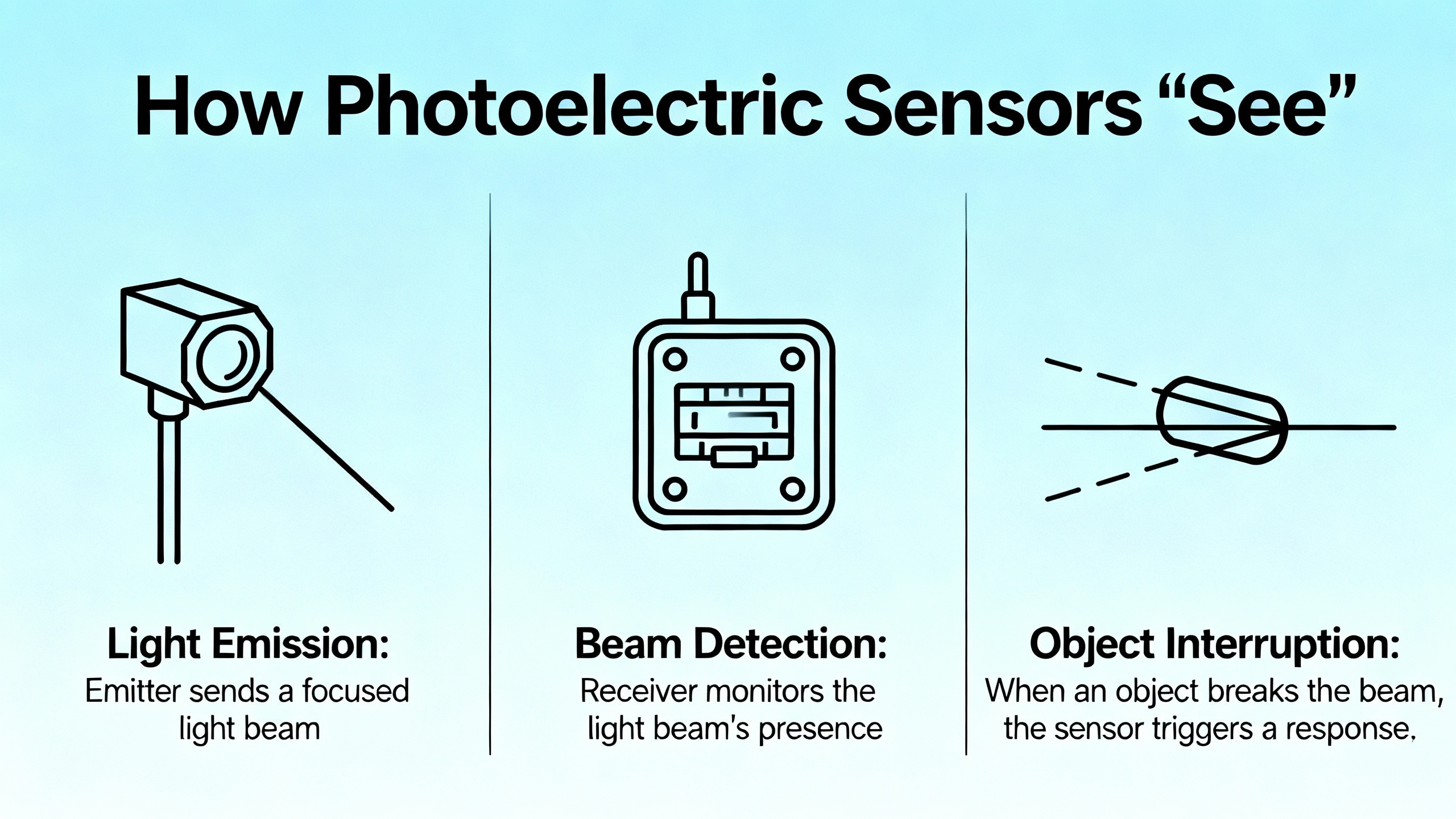
How Photoelectric Sensors “See”
Photoelectric sensors are non-contact devices that use light to detect objects. According to Omchele and multiple industrial automation sources, the core elements are an emitter (often an LED or laser), a receiver, and supporting electronics that turn the received light into an electrical signal. The sensor decides “object present” or “object absent” based on changes in that signal.
TTco’s fundamentals describe two foundational behaviors that almost every application reduces to. In a beam-break configuration, an object is detected when it blocks or reduces an existing light beam at the receiver. In a beam-make configuration, an object is detected when it reflects or diffuses enough light into the receiver to cross a threshold.
From those basics, three mainstream sensing modes dominate industrial object detection, as described by Control.com, Bastian Solutions, Omchele, and others.
Through-beam (opposed mode)
In through-beam systems, the emitter and receiver sit in separate housings facing each other. The receiver expects a continuous, strong beam. When an object interrupts that beam, the sensor output changes state.
The research notes from Wolf Automation and Control.com characterize through-beam as the most reliable and longest-range style. Wolf Automation notes that good through-beam devices can resolve features down to roughly 0.03 mm, which is on the order of about 0.001 inch, and that they are largely indifferent to object color, surface finish, or angle of approach as long as the beam is actually broken and alignment is maintained. Control.com emphasizes that these sensors achieve the longest detection ranges and are well suited to difficult environments with fog, dust, or dirt.
The trade-off is that opposed-mode demands careful alignment between two housings. That is the first place many installations fall down.
Retroreflective
Retroreflective sensors combine emitter and receiver in one housing and rely on a separate reflector mounted across the path. The sensor looks for its own light bouncing off that reflector. When an object blocks or scatters the returning beam, the output changes.
Control.com and TTco describe this as a medium-range, easier-to-wire option because only one powered device is mounted in the field. TTco notes that a retroreflective beam can usually tolerate about ten to fifteen degrees of angular skew and still return a strong signal, which gives a bit more forgiveness than pure through-beam alignment. However, highly reflective targets can imitate the reflector and cause false detections unless polarization techniques and proper geometry are used, and retroreflective configurations still depend heavily on the reflector being mounted in a stable, well-aligned “sweet spot.”
Diffuse (reflective proximity)
Diffuse sensors also house emitter and receiver together, but there is no reflector. The target itself becomes the reflector. Light hits the object, and some portion returns to the receiver. The sensor interprets changes in that returned intensity as presence or absence.
Control.com and BxuanSensor highlight diffuse sensors as the go-to choice for short-range, high-precision detection in assembly and logistics, especially when only one side of the process is accessible. Many modern diffuse sensors support foreground and background suppression so the device responds to a defined zone and ignores distant backgrounds.
The trade-off is that performance depends strongly on the target’s color, texture, and angle. Alignment and calibration are therefore less about lining up two housings and more about carefully tuning sensitivity and the sensing window to distinguish the real target from the background.
Why Alignment Problems Are So Common
On paper, alignment is straightforward. In real plants, several factors interact to create marginal setups that slowly drift into failure. The research notes and practical guides from chi-swear, Control.com, Omchele, TTco, and BxuanSensor all point to recurring themes.
First, mechanical mounting is often treated as an afterthought. Brackets are flexible, improvised, or attached to vibrating structures. Even a well-aligned through-beam pair can shift a fraction of an inch over time, especially when operators lean on guarding, bump frames with pallets, or adjust things during changeovers. TTco’s opposed-mode guidance emphasizes that the most reliable sensing occurs when alignment is held rigidly; once that assumption is violated, range and reliability drop quickly.
Second, many installations run with gain turned up too high. Orient-Optocoupler and EMX both emphasize that sensitivity should be set to what the application truly requires, not simply to maximum. When gain is excessive, the sensor can appear “aligned” even while the optics are marginal, and small changes in dust, lens contamination, or mechanical shift push the device over the edge into intermittent behavior.
Third, ambient light and reflections create phantom beams. The chi-swear troubleshooting article and TTco fundamentals both mention that bright background reflections or strong external lighting can confuse sensors. Modern devices often use pulsed LEDs and modulation to reject ambient light, but that immunity is not absolute. Sunlight, skylights, high-bay lighting, and reflective backgrounds can all build up enough energy at the receiver to hide an object or create spurious transitions.
Fourth, the link between detection range and alignment angle is often ignored. Control.com points out that the narrower the beam, the more precise the positioning but the more alignment-critical the installation becomes. Laser-based through-beam or precise diffuse sensors give excellent spatial resolution, but they offer less forgiveness if the beam drifts off the target by even a small angle.
Finally, electrical issues masquerade as alignment problems. The chi-swear article lists inadequate power supply, cable faults, and poor shielding as common sources of unpredictable behavior. When power is marginal or wiring is compromised, the sensor’s internal thresholds and timing can shift, and operators often blame “alignment” when the root cause is actually electrical.

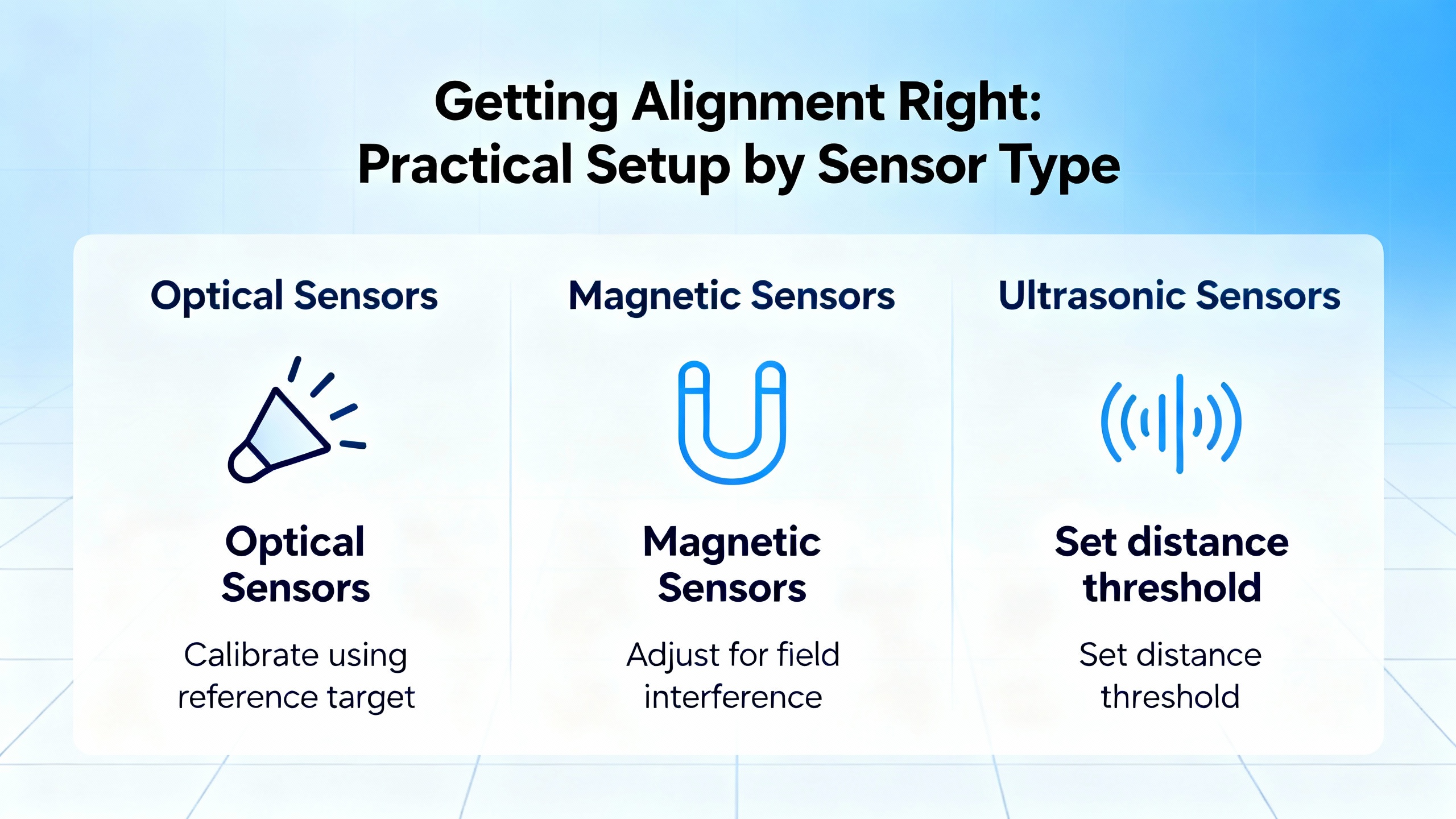
Getting Alignment Right: Practical Setup by Sensor Type
Alignment best practices vary with each sensor mode. Below are methods derived from manufacturer and integrator guidance that consistently produce robust installations.
Through-beam alignment that stays aligned
Opposed-mode or through-beam sensors reward careful setup with exceptional reliability. Control.com, Wolf Automation, TTco, and BxuanSensor all portray them as the most dependable way to detect objects in dirty or long-range environments.
Good alignment starts with solid mechanics. Both emitter and receiver should be mounted on rigid brackets attached to stable structure, not on flimsy sheet metal that flexes when bumped. Mounting both devices to the same frame or to well-referenced opposing structures helps avoid slow drift as equipment expands, contracts, or vibrates.
Once the hardware is secure, coarse alignment is done visually. The emitter is pointed roughly toward the receiver, and built-in alignment indicators or status LEDs are used as a qualitative guide. Many sensors provide a bar graph, simple “signal strength” LED, or teach button that shows when the beam is hitting the receiver solidly. As TTco describes in its opposed-mode guidance, your goal is not just to make the receiver see the beam, but to maximize contrast between “beam present” and “beam blocked.”
Fine alignment involves small adjustments while watching the receiver’s indicator or the actual electrical output on a meter. For opposed-mode, this often means adjusting horizontal and vertical angle on the emitter until the receiver’s signal is centered in its “good” window, then making minimal adjustments to the receiver if needed. When everything is stable, the beam should stay solid even if you lightly tap the brackets or shift the emitter a small amount.
Wolf Automation’s note on through-beam resolution underscores why this care pays off. With the ability to detect features around a thousandth of an inch, you have a very sharp optical edge. That sharpness amplifies any misalignment, so a little extra time with a wrench and a meter during commissioning avoids chronic nuisance calls later.
Retroreflective alignment and the Haush method
Retroreflective sensors are widely used in access control, gates, and doors, as EMX points out, because they simplify wiring to a single powered device. The challenge is positioning the reflector so the sensor sees a strong, stable return that still leaves room for the target to interrupt.
The Haush method described by EMX is a practical, equipment-free way to achieve this. The process begins by mounting the photoeye near the gate or door with its gain or sensitivity set to about one third of maximum. That lower gain prevents the sensor from “seeing everything” and masking alignment problems.
You then stand several feet away, with EMX recommending roughly four to six feet, holding the reflector in your hand. By moving the reflector around, you intercept the beam and watch the sensor’s status indicators, such as the green and red LEDs mentioned for EMX’s IRB-RET device. When those indicators show a solid signal, you know the basic alignment between sensor and reflector is correct at that distance.
Next, you keep the photoeye in its active state and slowly walk back toward the intended final reflector location, keeping the reflector aimed at the sensor. At the approximate operating distance, you move the reflector up, down, left, and right to find the “active target area,” which EMX describes as a zone roughly a couple of feet in diameter where the signal remains solid. If the signal drops out before you reach the planned distance, you can increase gain to around half of its maximum and repeat the process.
Once that active zone is identified, the reflector is mounted as close to the center of this area as possible. This positioning maximizes alignment margin and greatly reduces callbacks due to marginal setups. After the reflector is securely mounted and alignment confirmed, EMX recommends increasing gain to its maximum to create the strongest operating margin. Protective hoods on both sensor and reflector, also emphasized by EMX, help shield optics from weather and contaminants, further improving stability.
TTco’s retroreflective fundamentals complement this method. They note that retroreflective sensors tolerate a modest amount of skew between sensor and reflector, but shiny targets can mimic the reflector and cause false trips. In those cases, polarized retroreflective devices and careful geometry are necessary, and alignment should be verified with actual product rather than only with a bare reflector.
Diffuse sensor setup and background control
Diffuse sensors demand a slightly different mindset because the object itself is the reflector. As Orient-Optocoupler and BxuanSensor explain, you are not aligning to a separate receiver or reflector; you are aligning the sensor’s field of view to see the target and ignore the background.
Correct installation and wiring come first. Orient-Optocoupler stresses verifying that the power supply matches the sensor’s specifications before any adjustments, and ensuring that mounting orientation gives the sensor a clear view of the target path.
Sensitivity adjustment is the heart of diffuse alignment. Orient-Optocoupler recommends placing a representative object at the intended detection distance and gradually increasing sensitivity until the sensor reliably detects it. You then test at slightly closer and farther positions to ensure you have a usable detection window rather than a single narrow spike.
Modern diffuse sensors, as described in Control.com’s and BxuanSensor’s notes, often include teaching or background suppression functions. A common workflow is to teach the sensor the background with no object present, then teach it again with the object in place. The sensor calculates internal thresholds to distinguish between the two. The key is to perform this teach procedure under realistic lighting and at the actual angles and surfaces the sensor will see in operation. If you teach in a lab with matte targets and then install above shiny stainless equipment under skylights, the calibration will not hold.
Where backgrounds are especially problematic, TTco points to convergent or “V-axis” modes and fiber-optic solutions as ways to focus the sensing region or reach tight spaces. These strategies are alignment tools in their own right, letting you physically constrain what the sensor can see so less is left to sensitivity adjustments alone.
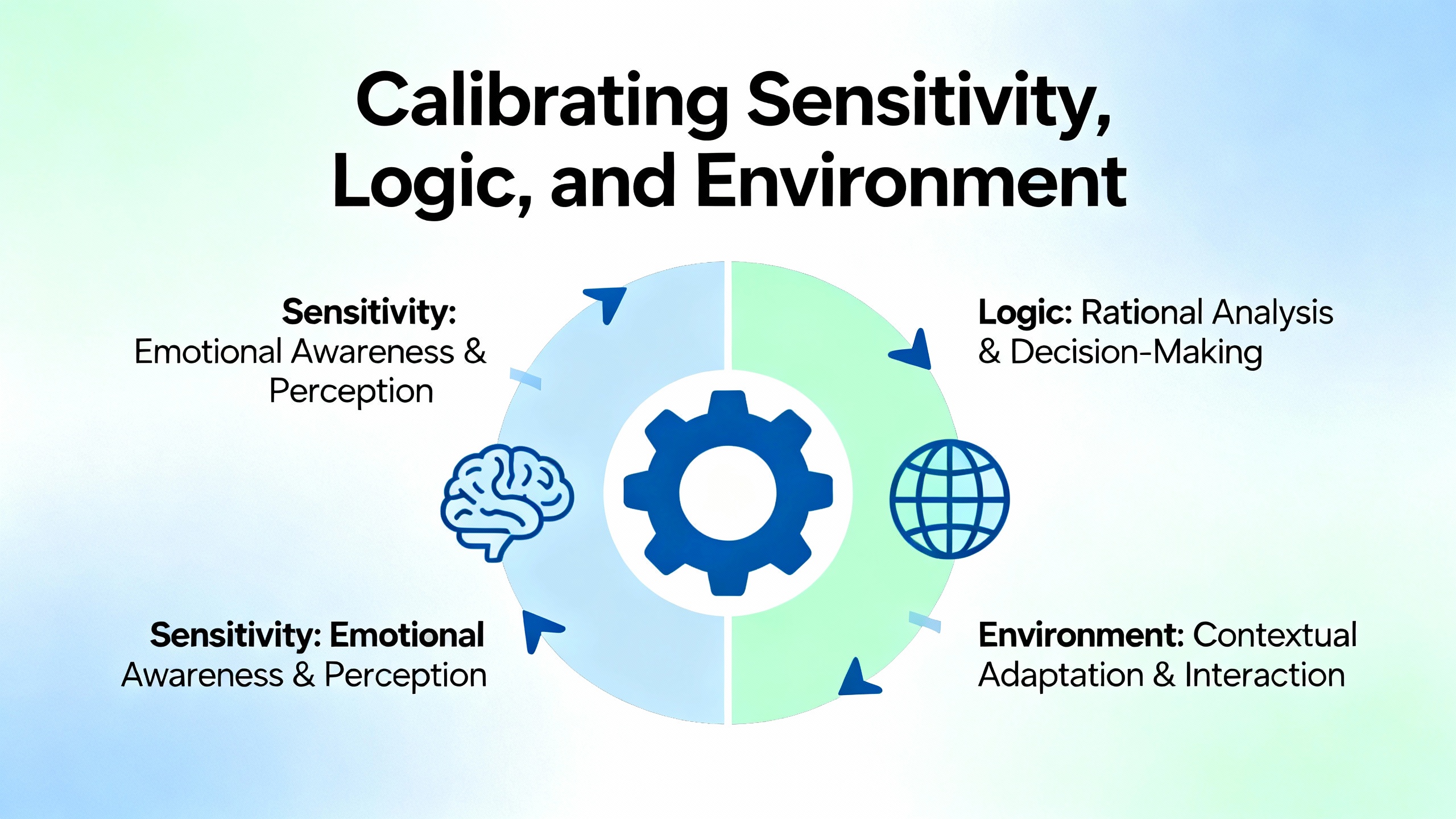
Calibrating Sensitivity, Logic, and Environment
Alignment sets the geometry; calibration sets the thresholds and behavior. Several sources, including Orient-Optocoupler, TTco, BxuanSensor, Meyer, and Valin, highlight calibration as the difference between a sensor that works on day one and one that keeps working years later.
Sensitivity and detection margin
Orient-Optocoupler emphasizes that diffuse sensors depend heavily on a correctly set sensitivity knob or screw. Too low, and small or dark objects are missed. Too high, and reflections or minor movements create false triggers. Through-beam and retroreflective sensors also offer sensitivity or gain settings, which should be chosen based on target size, reflectivity, and environmental noise rather than simply turning them fully clockwise.
BxuanSensor adds that microsecond-level response times and high sensitivity are valuable only when the system is stable. Their guidelines for predictive quality stress monitoring signal trends over time, which requires that initial calibration establish a known “good” signal level with adequate margin. In practical terms, after alignment, you want a clear difference between the signal when the beam is clear and when it is blocked, with operating thresholds placed comfortably between those two levels.
Light-on vs dark-on logic
Orient-Optocoupler notes that many photoelectric sensors support two basic output logics. In light-on mode, the output is active when the beam is present. This can be useful when the absence of an object should trigger an action, such as a missing-part detection station. In dark-on mode, the output is active when the beam is interrupted, which is more intuitive for classic presence detection on conveyors.
Choosing the correct logic is part of calibration because it must match your control strategy and safety requirements. Inconsistent use of light-on and dark-on logic across similar stations can make troubleshooting harder for technicians and lead to misinterpretation of HMI indicators. During commissioning, the sensor’s logic mode, the controller’s assumed logic, and the physical behavior should all be verified together with real product.
Foreground and background suppression
Control.com highlights foreground and background suppression as key features for diffuse sensors. Instead of a simple threshold on absolute light level, these devices define a detection zone and actively suppress responses from closer or farther surfaces.
Calibration here typically involves teaching a near unwanted surface, such as a guard rail, and a far background, such as a wall or piece of equipment, then teaching the actual object zone. When done correctly, the sensor responds only when product passes through that zone and ignores both the closer and farther structures. BxuanSensor underscores that programming sensors to monitor specific limited areas is a powerful way to filter out dust and noise, which also extends sensor service life because lenses do not have to be kept perfectly clean to maintain absolute light levels.
Calibrating for the environment
The chi-swear troubleshooting guide and the Meyer article on optical sorters both stress environmental calibration. Meyer notes that ambient light must be controlled so sensors and cameras can distinguish good from bad product consistently, and that temperature and humidity swings can alter sensor readings over time.
In practice, this means aligning and calibrating sensors with typical ambient lighting turned on. If external doors are commonly open, perform calibration under those conditions. Do not tune sensors at night with half the hall lights off and expect them to behave the same at noon under full sun.
Meyer also recommends structured maintenance schedules: regular cleaning of optics, monthly checks of sensor alignment and software, and annual inspections of mechanical and lighting components. BxuanSensor aligns with this, advocating preventive maintenance that includes cleaning optical faces, tightening connections affected by vibration or thermal cycling, and monitoring signal strength to detect gradual degradation before failure.
Omchele points out that high ingress protection ratings, such as IP67, and robust designs help sensors survive harsh, dusty, dirty, or moist environments, but even with rugged hardware, calibration should assume that some level of contamination and reflection will always be present.
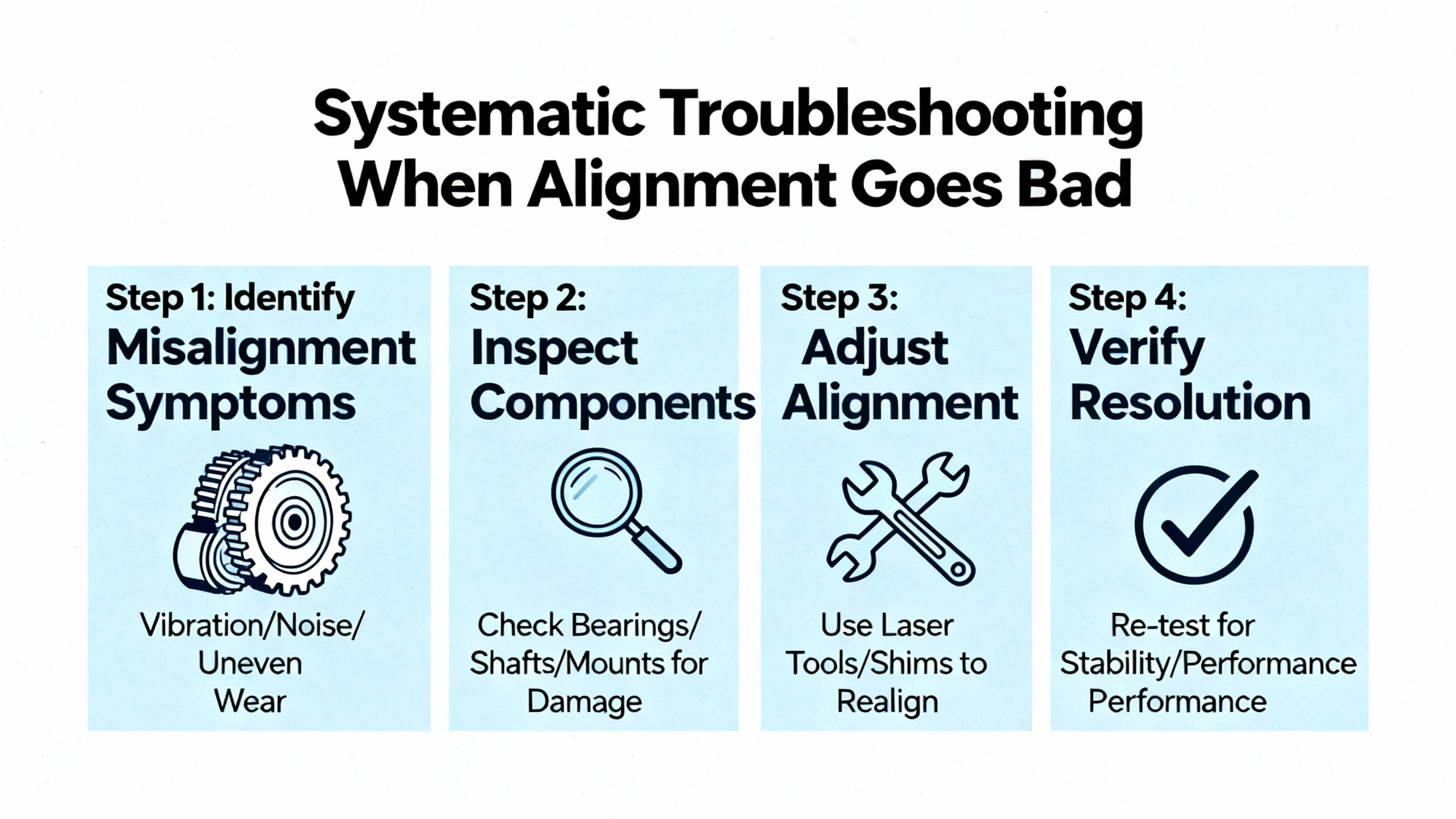
Systematic Troubleshooting When Alignment Goes Bad
When a line is tripping photoeyes randomly, the temptation is to twist every knob and loosen every bracket at once. The references from chi-swear, BxuanSensor, and Meyer advocate a methodical sequence instead, which in practice saves both time and guesswork.
The first check is power. The chi-swear guide explicitly recommends verifying voltage and current with proper instruments to ensure the sensor is within its specified tolerances. In the field, that means measuring supply voltage at the sensor terminals, not just at the panel, and watching for drops when other loads turn on. Undersized conductors, long runs, or overloaded power supplies can all drag sensors into marginal operation.
Once power is confirmed, attention shifts to the optics. Dust, oil mist, condensation, and product splatter accumulate on lenses and reflectors. The chi-swear article proposes a careful optical inspection and cleaning of emitter and receiver components to restore a clear optical path. Even small amounts of contamination can reduce received light enough that a system which was barely aligned begins missing objects or chattering.
Mechanical alignment comes next. For through-beam and retroreflective sensors, you can often see misalignment by loosening the bracket slightly and watching how the status LED or signal indicator changes as you move the housing. TTco’s guidance on opposed-mode and retroreflective sensing highlights that you want not only a valid signal but a strong one, with good contrast between clear and blocked states. If you find that the signal marginally toggles at rest, you know you are sitting on the edge of the sensor’s alignment window.
Cabling and electrical integrity should also be checked. The chi-swear notes suggest using cable testers and multimeters to verify continuity, insulation resistance, and shielding effectiveness. In practical terms, gently flexing cables while watching sensor outputs on a diagnostic screen often reveals intermittent faults. Any damaged connectors, crushed conduits, or poorly grounded shields can inject noise or intermittent power drops that mimic alignment problems.
Environmental influences must then be evaluated. The chi-swear article recommends analyzing temperature, humidity, and ambient light with appropriate tools, while Meyer’s optical sorter guidance discusses stable environmental conditions as key to consistent performance. On a line, that might mean temporarily shading a sensor from sunlight, switching off nearby floodlights, or placing non-reflective covers behind the target path to see whether false trips disappear. TTco’s and Omchele’s discussions of reflective backgrounds reinforce how often shiny machine surfaces create unexpected optical paths.
Only after power, optics, mechanical alignment, cabling, and environment are addressed does recalibration make sense. Meyer recommends using known “good” and “bad” reference samples where applicable, and relying on built-in calibration or teach routines. BxuanSensor adds the idea of monitoring trend data over time, ideally through integration with a SCADA or data logging system, to detect slow drift in sensor performance before it leads to failures.
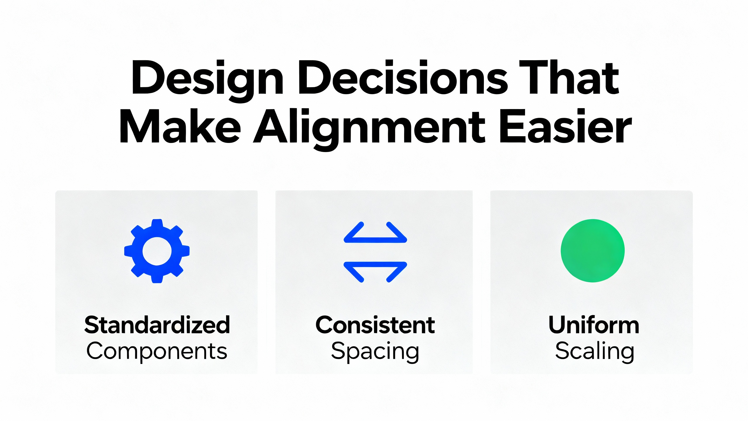
Design Decisions That Make Alignment Easier
Many alignment headaches are preventable if sensor selection and mounting strategy take alignment realities into account. The research notes from Control.com, Bastian Solutions, TTco, Valin, and JHFoster highlight recurring design patterns that help.
Control.com advises starting with a clear definition of the application and environment: object size, shape, material, surface finish, speed, required accuracy, ambient light, dust, humidity, and temperature. Through-beam sensors are often preferred for long-range, high-contamination, or transparent-media applications. Retroreflective sensors provide a good compromise for medium distances and diverse objects, while diffuse sensors excel in short-range, high-precision detection where strong background suppression is feasible.
TTco and Bastian Solutions emphasize that opposed-mode (through-beam) sensing offers the highest reliability, especially with small parts or in harsh, dirty, or wet environments, at the expense of needing two separate housings and precise alignment. Retroreflective sensors, while easier to wire, must be chosen and aligned carefully when dealing with transparent or shiny products. Diffuse sensors are cost-effective and mechanically simple but are more sensitive to object and background characteristics.
The table below summarizes alignment-relevant trade-offs derived from these sources.
| Sensor mode | Alignment difficulty | Typical strengths | Common alignment pitfalls |
|---|---|---|---|
| Through-beam | High: two housings to align | Longest range, highest reliability, tolerant of dust and color | Flexible brackets, vibration, and over-tight gain settings |
| Retroreflective | Moderate: sensor plus reflector | Single powered device, good medium range, simple wiring | Reflector in wrong spot, shiny targets mimicking reflector |
| Diffuse | Lower geometric alignment but higher calibration demands | Simple mechanics, short-range precision, background suppression | Poor sensitivity tuning, unaccounted-for reflective backgrounds |
Control.com also notes the relationship between beam angle and alignment. Narrow beams and laser variants give higher precision and longer ranges, but require more precise mechanical alignment. Wider beams and larger receivers are more forgiving but can introduce ambiguity in exactly where detection occurs.
Valin and JHFoster add that fiber-optic photoelectric sensors and specialized geometries are useful in tight or harsh spaces. Fiber-optic tips can be mounted very close to the action, while the electronics sit in a protected location, simplifying alignment in cramped or hot environments.
Finally, modern smart sensors often combine multiple operating modes and outputs, including discrete, analog, and digital interfaces such as IO-Link, as noted by Control.com. While the notes emphasize these features mainly for flexibility and integration, in practice they also help alignment and calibration by exposing real-time signal levels and diagnostic data, allowing technicians to see actual margins instead of relying only on a single indicator LED.
Short FAQ: Alignment and Calibration in Daily Operation
How precise does alignment really need to be?
The practical answer is that alignment must provide a strong, stable signal with clear contrast between “object present” and “object absent” under worst-case conditions. Through-beam and laser-based sensors can detect extremely small features, which means even subtle misalignment reduces that contrast. Using the manufacturer’s indicator LEDs or signal-level readouts, as TTco and others describe, is the best guide: you want the signal comfortably inside the “good” window, not just barely on the edge.
When should I choose through-beam instead of diffuse or retroreflective if alignment is difficult?
Control.com, TTco, and Bastian Solutions consistently position through-beam sensors as the first choice when reliability matters more than wiring simplicity, especially in dusty environments or when detecting small or transparent objects. If you can physically mount both emitter and receiver with rigid, stable brackets, the extra effort during installation pays off in fewer alignment problems later. Where mounting on both sides is impossible, retroreflective or diffuse sensors with careful calibration and, in some cases, specialized optics are the practical alternatives.
Can I rely only on “auto-teach” calibration and ignore manual alignment checks?
Teach functions and automated calibration routines, as described by Control.com, BxuanSensor, and Meyer, are powerful tools, but they assume the underlying mechanics and optics are sound. If brackets are loose, reflectors are marginal, or ambient light is drastically different during operation than during teaching, the resulting calibration will be fragile. It is good practice to combine auto-teach with verification using real product, checks of signal margin, and periodic revalidation as part of your maintenance program.
Closing
Photoelectric sensors are not difficult devices, but they are unforgiving of lazy alignment and casual calibration. When you treat mounting, alignment, and environmental calibration with the same discipline you apply to PLC code or safety circuits, the payback is immediate: fewer nuisance stops, cleaner diagnostics, and equipment that just runs. As a project partner, my recommendation is simple: build robust alignment and calibration practices into your standards once, and every sensor you install afterward becomes that much easier to trust.

References
- https://www.bxuansensor.com/blog/how-does-a-photoelectric-sensor-improve-process-efficiency777
- https://www.emxaccesscontrolsensors.com/calibrating-retroreflective-photoeyes-with-the-hausch-method/
- https://kwoco-plc.com/adjust-photoelectric-sensor/
- https://www.omchele.com/photoelectric-sensor-working-principle/
- https://www.orient-optocoupler.com/news/how-do-you-adjust-a-photoelectric-sensor
- https://www.ttco.com/sensors/fundamentals?srsltid=AfmBOooYp_teVU4ZfEOqbp1W2bm_RUsHV3izHbIymhdgLRl3O_y8_Pdl
- https://www.zjhlgk.com/blog/how-can-photoelectric-sensors-improve-automation-efficiency
- https://www.allworldmachinery.com/blog/15/best-practice-for-photoelectric-sensor-installs?srsltid=AfmBOopnB5A6BvfLNUo09aPB4Vr642xE-6mAcCvWnAhFbi0VqJaW0x-d
- https://www.bastiansolutions.com/blog/what-are-photo-eye-sensors-and-how-do-they-improve-system-automation/?srsltid=AfmBOor1jzaLhuNlOrD5lU4TCZ8VNh6Ib_NkI3VJTaDk9mgnyITJL4Jx
- http://chi-swear.com/pt/how-to-fix-a-photoelectric-sensor-that-does-not-work/
Keep your system in play!
Top Media Coverage
Categories


Related articles Browse All
-
 amikong NewsSchneider Electric HMIGTO5310: A Powerful Touchscreen Panel for Industrial Automation2025-08-11 16:24:25Overview of the Schneider Electric HMIGTO5310 The Schneider Electric HMIGTO5310 is a high-performance Magelis GTO touchscreen panel designed for industrial automation and infrastructure applications. With a 10.4" TFT LCD display and 640 x 480 VGA resolution, this HMI delivers crisp, clear visu...
 -
 BlogImplementing Vision Systems for Industrial Robots: Enhancing Precision and Automation2025-08-12 11:26:54Industrial robots gain powerful new abilities through vision systems. These systems give robots the sense of sight, so they can understand and react to what is around them. So, robots can perform complex tasks with greater accuracy and flexibility. Automation in manufacturing reaches a new level of ...
 -
 BlogOptimizing PM Schedules Data-Driven Approaches to Preventative Maintenance2025-08-21 18:08:33Moving away from fixed maintenance schedules is a significant operational shift. Companies now use data to guide their maintenance efforts. This change leads to greater efficiency and equipment reliability. The goal is to perform the right task at the right time, based on real information, not just ...


- Q&A
- Policies How to order Part status information Shipping Method Return Policy Warranty Policy Payment Terms
- Asset Recovery
- We Buy Your Equipment. Industry Cases Amikong News Technical Resources Why choose us
- ADDRESS
-
 32D UNITS,GUOMAO BUILDING,NO 388 HUBIN SOUTH ROAD,SIMING DISTRICT,XIAMEN
Leave Your Comment