
-
Please try to be as accurate as possible with your search.
-
We can quote you on 1000s of specialist parts, even if they are not listed on our website.
-
We can't find any results for “”.
PLC Output Module Failure Troubleshooting: Repair Strategies
As someone who has spent decades commissioning and maintaining PLC systems in plants that cannot afford to stop, I can tell you that output module failures are one of the fastest ways to turn a steady production day into a very expensive emergency. Most studies and field reports agree that a large share of PLC problems trace back to I/O paths, wiring, and field devices rather than the CPU itself. Global Electronic Services and several technical guides point out that many PLC failures sit in that narrow band where the controller, the I/O module, and the field wiring meet. If you can systematically troubleshoot output modules, you can prevent most of the ugly, drawn‑out downtime events that make everyone’s phone ring.
This article walks through how output modules work, how they fail, and how to diagnose and repair them with a structured, field‑proven approach. The focus is practical: what to check first, which measurements matter, when to repair, and when to replace. The goal is not just to get the line running again, but to prevent the same fault from waking you up next month.
Where Output Modules Fit In The PLC Architecture
A PLC is an industrial computer that continually monitors inputs, runs logic in the CPU, and drives outputs to real‑world devices. Multiple sources, from Control.com to maintenance guides from UpKeep and others, describe the basic pattern as input–logic–output. Input modules watch switches and sensors; the CPU executes the program; output modules energize loads such as relays, solenoids, contactors, indicators, and analog control signals.
Digital output modules are straightforward in concept. Each terminal on the module generally corresponds to one internal memory bit. When the program forces that bit from 0 to 1, the module switches its electronics and delivers voltage or current to the field device. When the bit is 0, the channel should be off. In reality, there is a lot that can go wrong between that memory bit and the device on the factory floor.
Analog outputs are similar in structure but different in behavior. Allied Reliability and other technical references note that analog signals are continuous, representing variables such as speed, pressure, or position, often as 0–10 V or 4–20 mA. Inside the PLC, those signals are represented as integer values across the available resolution, typically using a 16‑bit signed range. An analog output module converts that integer back into a proportional voltage or current to control a drive, valve, or other device. Analog failures can be subtle, but the same disciplined troubleshooting mindset applies.
The key point is this: the output module is the bridge between logic and hardware. When a machine does not move even though the logic says it should, the output path—from CPU bit, through the module, through the wiring, to the field device—is where you must think systematically.
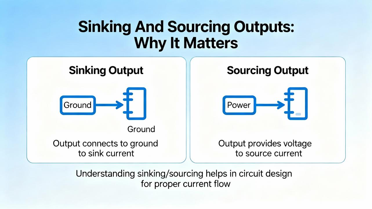
Sinking And Sourcing Outputs: Why It Matters
Control.com and other engineering resources emphasize that you cannot troubleshoot a module reliably if you do not understand whether it is sinking or sourcing. The difference is simply the direction of current flow, but it has major wiring and testing implications.
On a sourcing digital output module, the module supplies positive voltage out of each channel when the output is on. The load is connected between the module channel and the negative return, and current flows out of the module, through the load, back to the supply common. This is the most common pattern for 24 VDC outputs.
On a sinking digital output module, the module provides the path to ground when the output is on. The load is connected between the positive supply and the module channel. When the module turns on, current flows from the positive supply, through the load, into the module, and out to ground.
You can often infer the type by looking at the common terminal. A common ground or negative terminal often indicates a sinking module on the input side, and a common positive terminal often indicates a sourcing module on the output side, but training material and manufacturer manuals make it clear that appearances can deceive. Some modules require both positive and negative commons. When in doubt, the only correct answer is to read the datasheet.
A concise comparison looks like this:
| Output type | Typical common wiring | Current direction when ON | Typical use cases | Common troubleshooting trap |
|---|---|---|---|---|
| Sourcing | Common positive supply | From module to load to negative | Driving DC coils, lamps, small relays | Seeing the status LED on, assuming the field device must be powered, even when the common is missing |
| Sinking | Common ground or negative | From positive supply to load into module | Less common for outputs, sometimes used for specific architectures | Misinterpreting voltage readings because the technician expects the module to source voltage rather than sink current |
If you misidentify a sinking module as sourcing, or vice versa, your meter readings will not make sense and you may conclude the module has failed when the wiring is simply incorrect. Taking a minute to confirm the type and sketch the current path saves hours of confusion.
How Output Module Failures Show Up In The Field
From the plant floor point of view, output failures rarely announce themselves as “bad module.” Instead, they show up as symptoms: a motor that will not start, a valve that will not open, or a lamp that never lights even though the operator insists the HMI shows the command as active.
RealPars training material points out that roughly three quarters of I/O‑related failures are actually in the field devices and wiring, not in the PLC modules themselves. Global Electronic Services and other repair providers describe early warning signs such as unresponsive I/O, intermittent operation, fault lights on the I/O rack, and hot spots on modules. Output‑specific patterns typically include channels that never energize, channels that appear stuck on, intermittent outputs that chatter, or entire banks of outputs dropping out under load.
Older modules can also present misleading signs. Control.com notes examples where the status LED shows an output as on, but there is no actual voltage at the terminal because the internal switching device or the common connection has been damaged. On very old or stressed hardware, a channel can be electrically dead while the indicator still responds to the logic bit.
From a system integrator’s viewpoint, it is useful to think in three categories. A single channel failure usually points to a local overload, wiring fault, or field device issue. A whole module failure suggests power, backplane, configuration, or environmental problems. Repeated or intermittent failures over weeks often signal deeper issues such as poor grounding, electrical noise, or heat.
A Structured Troubleshooting Workflow For Output Modules
Most repair organizations recommend a stepwise approach rather than jumping straight to module replacement. Global Electronic Services stresses starting with basic electrical checks, then progressively isolating the root cause. RealPars and Control.com add practical detail around how to use I/O status LEDs and multimeters effectively. The following is the kind of workflow I expect from a competent technician on site.
Step 1: Stabilize Power, Grounding, And Environment
Before focusing on a specific output channel, confirm that the PLC and its I/O rack have clean, stable power. Automation‑focused reliability articles highlight power quality problems as a leading cause of controller and I/O trouble. Use a meter to verify that the PLC power supply input is within the specified voltage range and that any DC outputs, often 24 VDC feeding the I/O, are present and steady. Look for obvious issues such as loose terminals, discolored wires, and tripped breakers.
Ground integrity is equally important. Multiple sources, including The Automation Blog and other maintenance guides, emphasize that poor grounding and ground loops can cause intermittent, hard‑to‑trace I/O faults. Inspect the grounding conductors for damage or loose hardware, and verify continuity between the PLC ground and the facility ground with a meter where it is safe to do so.
While you are in the cabinet, scan for environmental stress. Articles from eWorkOrders, UpKeep, and Allied Reliability all warn that heat, humidity, dust, and corrosion accelerate PLC hardware failure. Look for clogged filters, blocked vents, moisture marks, or insect nests in remote panels. If a cabinet is running hot or shows signs of condensation, environmental control is part of the root cause even if the immediate symptom is an output that will not energize.
Step 2: Confirm Logic And Status
Next, verify that the controller actually intends to energize the output. You cannot troubleshoot an “off” output that the program is deliberately holding off. Use the PLC’s diagnostic display or programming software to confirm that the CPU is in run mode and that the output tag or address is true when you expect it to be.
If access to software is limited, status LEDs on the CPU and I/O modules are your first diagnostic tool. Control.com and RealPars both emphasize that these indicators, when used properly, let you troubleshoot many I/O problems without digging into ladder logic. If the output channel’s LED never lights under conditions where the logic should drive it, suspect configuration, addressing, or the module itself. If the LED follows the command perfectly, but the field device does not respond, you can shift your focus downstream.
Remember that LED indicators are not infallible. Several case studies show LEDs indicating an “on” state even when internal electronics are partially damaged. Always treat LEDs as hints, not proofs.
Step 3: Prove The Output Channel Electrically
Once you know the logic bit is on and the channel LED is lit, you need to confirm what is happening electrically at the terminal. This is where many technicians make or break the diagnosis.
For a typical 24 VDC sourcing output module, RealPars and Control.com recommend setting your multimeter to the appropriate DC range, placing the positive probe on the output terminal, and the negative probe on the common or ground. When the output is commanded on, you should see approximately the supply voltage, such as 24 V. When the output is off, the reading should drop close to zero. If the LED is on but the meter shows no voltage, you likely have either a failed channel or a missing or failed common connection.
For sinking outputs, the measurement logic is slightly different. You may need to measure between the supply positive and the module terminal, or use continuity tests under safe, de‑energized conditions to confirm that the channel is providing a path to ground when the output is on. In all cases, follow the wiring diagrams and manufacturer recommendations rather than guessing.
Control.com presents a critical safety reminder: never connect a PLC output terminal directly to ground or the negative DC bus without a load. Doing so effectively creates a short circuit that can damage internal components. An output channel must always see a resistive or otherwise appropriate load between the terminal and the return path.
Step 4: Prove The Field Circuit And Device
If the module is delivering correct voltage at its terminal when the output is on, the next suspect is the field circuit. The RealPars material is clear that field devices and their wiring account for the majority of I/O‑related failures. The fact that a sensor or actuator’s indicator light is on does not guarantee that it can draw enough current or provide a clean signal.
Work methodically from the module to the device. Check terminal blocks for loose or corroded connections. Verify that any in‑line fuses are intact by measuring across them. At the device itself—a contactor coil, a solenoid valve, or a lamp—measure whether the correct voltage appears at its terminals when the output is commanded on. If you see voltage at the module but not at the device, you have a wiring or terminal problem. If you see voltage at the device but no mechanical action, you have a failed load.
When it is safe and appropriate, you can temporarily substitute a known‑good test load or jumper to help locate the problem. For example, a small test lamp or indicator can verify that an output channel is able to drive a load even if the actual device is inaccessible. The point is to isolate each segment of the path until you find the break.
Step 5: Compare, Swap, And Isolate
When basic measurements indicate that one channel is suspect but the rest of the module behaves normally, comparative tests can provide clarity. Several repair guides recommend swapping suspected bad modules with known‑good ones, after fully powering down and following manufacturer instructions, to see whether the problem follows the module or stays with the slot, wiring, or device.
Within a module, comparing a suspect channel to a healthy one under identical conditions is often revealing. If two outputs are configured the same way but only one shows abnormal voltage under load, a localized hardware failure becomes more likely. If every channel feeding a particular group of devices has issues, look for shared wiring and fusing rather than condemning several channels at once.
Any swaps or tests must respect safety and configuration requirements. Changing a module type or firmware level without checking compatibility, which Global Electronic Services warns against, can introduce new faults. Always confirm part numbers and firmware requirements for the PLC platform before replacement.
Step 6: Document, Back Up, And Verify
Once the plant is running again, it is tempting to move on. That is usually where repeat failures are born. Maintenance literature from UpKeep, eWorkOrders, Solution Controls, and others consistently says the same thing: document what you found, capture any program or configuration changes, and update your backups.
At a minimum, record which module and channel failed, what measurements you took, and what you replaced or repaired. If you modified ladder logic or configuration to support testing, make sure you remove any temporary changes and restore correct settings. Then update the PLC backup in your chosen repository. Several sources recommend backing up PLC programs at least twice per year, and more frequently in critical systems or after significant changes. For output modules supporting safety interlocks or critical equipment, that discipline is non‑negotiable.
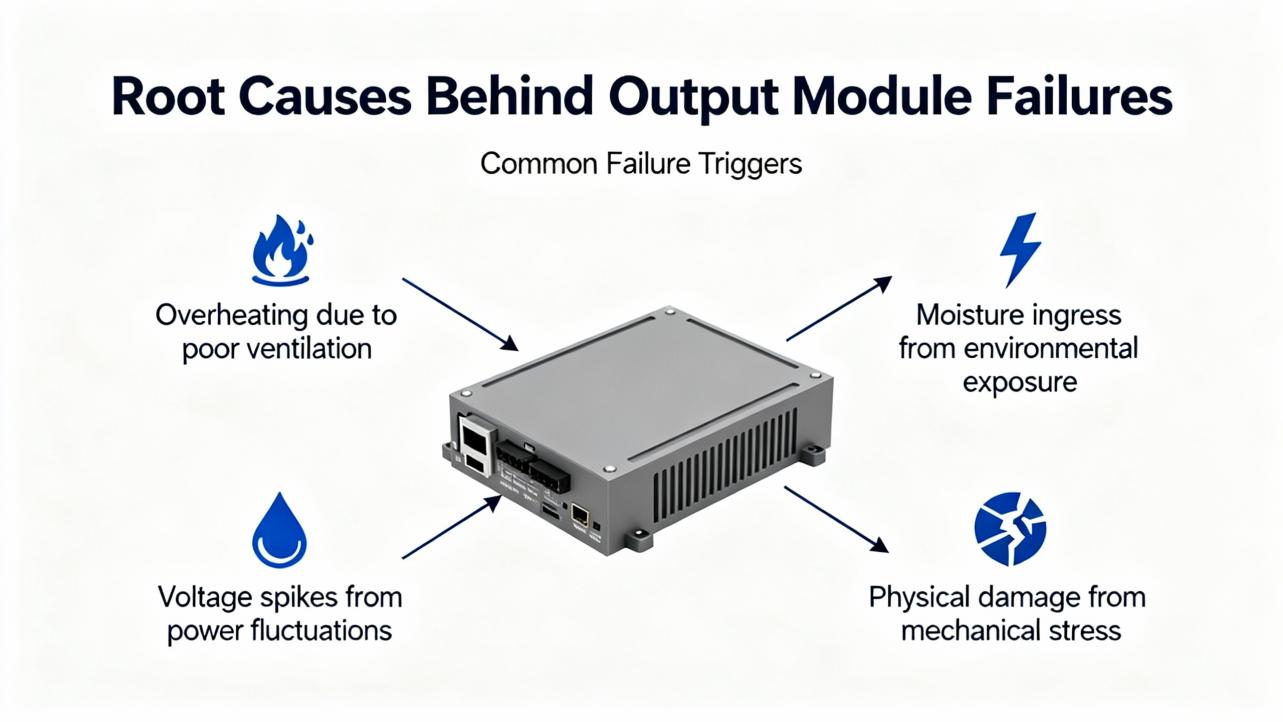
Root Causes Behind Output Module Failures
Once you have a specific failure on the bench, you should ask why it happened. The technical articles and repair guides show a consistent set of root causes, most of which are preventable with good design and maintenance.
Electrical Overload And Short Circuits
Output channels, especially solid‑state ones, have hard limits on the current they can deliver. RealPars highlights modules such as 24 VDC digital cards that are rated up to about 2 A per channel. Driving high‑current loads like motors directly from such outputs is a recipe for overheating and early failure. The standard practice is to use the output to control an interposing relay or contactor, letting the relay handle the heavy current while the module sees only a small coil load.
Short circuits are even more destructive. Skyline Electric and other service companies describe frequent burnout of I/O devices due to shorts, wiring mistakes, or insulation damage. Control.com explicitly warns that tying an output directly to ground can cause internal damage. Over time, repeated faults of this kind can degrade the module’s switching components even if the fuse clears, leading to intermittent or permanent channel failure.
Power Quality And Ground Integrity
Guides from The Automation Blog, eWorkOrders, and similar sources identify power problems as a common root cause for PLC issues. Voltage sags, surges, and interruptions can stress output modules and the devices they control. A sudden outage followed by an uncontrolled restart may leave some outputs in unexpected states or expose them to inrush currents beyond their ratings.
Good practice, as described in multiple maintenance articles, is to feed critical PLCs from conditioned power, with surge protection and often an uninterruptible power supply. This not only keeps the CPU alive long enough for a clean shutdown but also limits the stress on output modules and their loads. Reliable grounding and bonding protect against both electrical noise and fault currents, reducing the chance that an output’s reference point will float into a damaging condition.
Heat, Moisture, Contamination, And Aging
Environmental stress is a silent killer of output hardware. Automation safety and maintenance guides repeatedly point to high temperature, humidity, dust, and corrosive atmospheres as accelerants of failure. Excessive heat in a panel can dry out electrolytic capacitors, warp circuit boards, and weaken solder joints. Skyline Electric notes that capacitor lifetimes are on the order of ten years under normal conditions; hotter environments shorten that significantly.
Dust and metallic debris are another major factor. Allied Reliability’s case study of intermittent PLC logic deletion traced the root cause to metallic dust in the backplane, shifted every time a module was reseated. In that context, an output channel that works when first installed but later behaves erratically may not be a device problem at all; it may be contamination in the backplane or connector.
Moisture and condensation can corrode terminals and cause leakage paths or outright shorts across output circuits. Articles from eWorkOrders and Solution Controls recommend controlling humidity, sealing outdoor enclosures, and routinely inspecting for signs of moisture ingress.
Electrical Noise And Communication Issues
Electrical noise from electromagnetic and radio‑frequency interference is another recurring villain. Skyline Electric and PLC Technician training material both describe EMI and RFI from large motors, welding equipment, lightning, antennas, and handheld transmitters as sources of erratic PLC behavior and I/O failures. Noise can couple into long output cable runs, degrade signal integrity, and in extreme cases damage sensitive components.
Mitigation strategies discussed in these sources include shielding and segregating signal cables from high‑current power lines, enforcing restrictions on handheld transmitters near control cabinets, adding filters, and carefully managing grounding to avoid loops. For remote I/O over fieldbuses or Ethernet, communication problems can mimic output failures. Network reliability articles stress the importance of inspecting cables, connectors, and switches, and keeping firmware and security patches current so communication faults do not masquerade as hardware problems.
Configuration, Firmware, And Software Issues
Not every “bad output card” is electrically damaged. Several articles, including those from Global Electronic Services, Messung, and automation maintenance guides, call out configuration and firmware mismatches as common culprits. Installing a newer module in an older rack without confirming firmware compatibility, or copying a configuration from a different system without careful review, can lead to outputs that do not behave as expected even though the hardware is intact.
Software faults in the PLC program itself can also create what looks like an output failure. Logic conditions that never become true, safety interlocks that are permanently asserted, or poorly tested changes can leave outputs off when operators expect them on. Best practice is to validate any program change against expected behavior, review diagnostic logs, and compare the running program to a known‑good reference when behavior is suspicious.
Repair Or Replace: Making The Right Decision
Once you have identified a faulty output module or channel, the next decision is whether to repair components, refurbish the module, or replace it outright. Global Electronic Services and multiple maintenance guides provide useful principles.
Minor issues such as loose terminals, cracked solder joints, or easily replaceable fuses lean toward repair, especially if you have access to qualified electronics technicians and the module family is otherwise stable in your plant. Severe issues, such as visibly burned circuits, repeated failures on the same module, or damage from moisture or corrosion, almost always justify replacement.
Compatibility, age, and criticality all play a role. Replacing a very old module with a current model might require firmware updates or configuration changes. Some facilities, guided by recommendations from PLC maintenance articles, stock critical spares and maintain an inventory of module types, firmware levels, and locations to support quick, compatible replacement.
A practical way to think about the decision is summarized here:
| Situation on site | Repair is reasonable when | Replacement is safer when | Notes for project teams |
|---|---|---|---|
| Single channel failure, rest of module healthy | Problem traced to external wiring, fuse, or a terminal; no visible damage on the card | Channel repeatedly fails or card shows heat damage | Check for overloads or incorrect load sizing before reusing the module |
| Intermittent outputs with no visible damage | Issue linked to loose connectors or backplane seating; cleaning resolves the problem | Intermittence returns quickly or aligns with environmental extremes | Consider panel cooling, dust control, and vibration isolation in redesigns |
| Multiple channels dead on one module | Diagnostics reveal configuration errors or missing common wiring | Proper wiring confirmed and module still does not drive loads | Verify that replacement firmware and part numbers are compatible with CPU and rack |
| Modules in harsh, hot, or dirty environments | Module is relatively new and failure clearly tied to a single external event | Module family has reached expected life or panel conditions are chronically poor | Long‑term fix is usually environmental control plus planned refresh of I/O modules |
In highly critical applications, some organizations follow the guidance from PDFSupply and similar maintenance experts by keeping complete spare racks or at least a percentage of modules in stock, enabling fast replacement during outages.
Designing And Maintaining Systems To Protect Output Modules
Troubleshooting is only half of the equation. As a systems integrator, I always push clients to design and maintain their systems in ways that make output failures less likely and easier to diagnose when they do occur.
Design Choices That Protect Outputs
Proper design can dramatically extend the life of output modules. RealPars recommends using interposing relays when output currents approach module limits, particularly for inductive loads such as solenoid valves and motor starters. This not only keeps current within ratings but also provides a convenient place to add surge suppression, which reduces voltage spikes when coils de‑energize.
Cable routing is another design lever. EMI/RFI guidance from Skyline Electric and PLC training sources underscores the need to separate low‑level signal and control wiring from high‑current power conductors and noisy equipment. Shielded cables, correctly terminated at one end, and careful grounding practices help keep noise out of both input and output circuits.
The choice of enclosures and cooling is just as important. Maintenance articles stress the benefits of using appropriately rated enclosures with adequate ventilation or even active cooling in hot environments. Locating PLC panels away from direct heat sources, while still near the equipment they control, reduces thermal stress on output modules and other electronics.
Preventive Maintenance Focused On Outputs
Preventive maintenance programs described by UpKeep, eWorkOrders, Solution Controls, Messung, and others all converge on a few essentials that directly protect output hardware.
Routine visual inspections should include checking I/O modules and their terminals for discoloration, looseness, or corrosion. Dust and debris must be removed from modules and backplanes because, as several authors note, PLC hardware is not inherently dust‑proof. Cleaning or replacing enclosure filters and ensuring that documentation or tools do not block vents maintain airflow, which in turn keeps module temperatures in a safe range.
Electrical maintenance should cover tightening terminals, verifying that power supplies remain within specification, and checking that PLC current draw does not exceed rated capacities. For analog outputs, periodic calibration of circuit cards, recommended on a roughly six‑month cycle by some maintenance guides, ensures that control signals remain accurate.
Finally, and often neglected, is backup and documentation discipline. Multiple sources recommend maintaining up‑to‑date backups of PLC programs and I/O configurations, stored in safe, environmentally controlled locations away from EMI, heat, and moisture. When output modules fail, those backups allow you to reload configurations quickly and confirm that any replacement modules are set up correctly.
Training, Documentation, And Culture
Technical best practices do not stick without people and process. Training materials from PLC Technician programs, RLConsulting’s maintenance guidance, and Messung’s recommendations all stress building an internal culture of PLC awareness.
That culture starts with knowing what you have. Maintaining an inventory that lists each PLC, I/O rack, module type, firmware level, and critical loads helps technicians troubleshoot and plan upgrades. Ensuring that at least one person on each shift can interpret I/O diagrams, understand sinking versus sourcing, and use a meter intelligently on live systems directly improves mean time to repair.
Clear, up‑to‑date documentation of wiring and logic is the best gift you can give your future self or the next contractor who walks in the door. When I find neat drawings, labeled terminals, and consistent tag naming, I know I can get a plant back online quickly. When those are missing, even a simple output issue can consume hours.
Short FAQ: Practical Questions On Output Module Failures
Q: How can I tell quickly whether the problem is the output card or the field device? A good rule, supported by field data from RealPars and others, is to trust your measurements more than your intuition. If the PLC logic bit and the module’s output LED are on, measure voltage at the output terminal and at the device. If the module never delivers voltage even though the bit is on, suspect the card or its common wiring. If the module delivers correct voltage but the device does not respond or voltage never reaches it, suspect wiring or the device itself. Most of the time, the problem lies in the field path rather than the module.
Q: When should I plan to replace output modules proactively rather than waiting for failure? Maintenance and reliability articles suggest looking at a mix of age, environment, and failure patterns. If modules operate in hot, dirty, or corrosive environments, or if components such as capacitors are approaching their expected service life, proactive replacement during planned outages can be cheaper than emergency downtime. Recurrent failures on the same family of modules are also a signal that age or design limits are being reached.
Q: How often should PLC outputs and their associated logic be tested? There is no single number, but industry guidance points to pairing testing with your preventive maintenance schedule. For critical interlocks and safety‑related outputs, annual or even more frequent proof testing is common, often aligned with shutdowns. At the very least, tie testing into the same cycles you use for backups, environmental checks, and calibration, which many references place at intervals from several months to twice per year depending on risk.
Closing Thoughts
Output modules are not glamorous, but in real plants they decide whether metal moves, valves shift, and product flows. With a structured troubleshooting approach, grounded in sound electrical practice and supported by disciplined maintenance, most output failures can be diagnosed and resolved quickly without guesswork. If you treat your PLC outputs as critical assets rather than anonymous cards in a cabinet, they will repay you in uptime, safer operations, and fewer late‑night calls.
References
- https://faculty.slcc.edu/provost/syllabi_database/fall2025_team_2040_101.pdf
- https://streamer.gulfcoast.edu/TECH/DEavey/EST%202542C%20Programmable%20Logic%20Controllers/PLC%20PowerPoints/Lab%2016%20PowerPoints/Lab%2016%20Troubleshooting%20Labs.pdf
- https://www.plctalk.net/forums/threads/troubleshooting-ab-analog-output-module.135175/
- https://www.empoweredautomation.com/best-practices-for-implementing-automation-plc-solutions
- https://www.aesintl.com/plc-faults-and-troubleshooting-procedures/
- https://www.alliedreliability.com/blog/the-case-for-proper-plc-maintenance
- https://automationforum.co/common-causes-of-programmable-logic-controllerplc-failure-and-mitigation-strategies/
- https://www.messungautomation.co.in/plc-maintenance-and-troubleshooting-ensuring-smooth-operations/
- https://hale-eng.co.uk/top-7-causes-of-plc-communication-failures-and-how-to-prevent-them/
- https://gesrepair.com/diagnosing-and-repairing-plc-module-failures/
Keep your system in play!
Top Media Coverage
Categories


Related articles Browse All
-
 amikong NewsSchneider Electric HMIGTO5310: A Powerful Touchscreen Panel for Industrial Automation2025-08-11 16:24:25Overview of the Schneider Electric HMIGTO5310 The Schneider Electric HMIGTO5310 is a high-performance Magelis GTO touchscreen panel designed for industrial automation and infrastructure applications. With a 10.4" TFT LCD display and 640 x 480 VGA resolution, this HMI delivers crisp, clear visu...
 -
 BlogImplementing Vision Systems for Industrial Robots: Enhancing Precision and Automation2025-08-12 11:26:54Industrial robots gain powerful new abilities through vision systems. These systems give robots the sense of sight, so they can understand and react to what is around them. So, robots can perform complex tasks with greater accuracy and flexibility. Automation in manufacturing reaches a new level of ...
 -
 BlogOptimizing PM Schedules Data-Driven Approaches to Preventative Maintenance2025-08-21 18:08:33Moving away from fixed maintenance schedules is a significant operational shift. Companies now use data to guide their maintenance efforts. This change leads to greater efficiency and equipment reliability. The goal is to perform the right task at the right time, based on real information, not just ...


- Q&A
- Policies How to order Part status information Shipping Method Return Policy Warranty Policy Payment Terms
- Asset Recovery
- We Buy Your Equipment. Industry Cases Amikong News Technical Resources Why choose us
- ADDRESS
-
 32D UNITS,GUOMAO BUILDING,NO 388 HUBIN SOUTH ROAD,SIMING DISTRICT,XIAMEN
Leave Your Comment