
-
Please try to be as accurate as possible with your search.
-
We can quote you on 1000s of specialist parts, even if they are not listed on our website.
-
We can't find any results for “”.
How to Select a Safety PLC for SIL 3 Functional Safety Requirements
When someone asks me for a “SIL 3 safety PLC,” my first reaction is not to send a price list. It is to ask why they think they need SIL 3 and what the complete safety function looks like from sensor to final element. After a few decades in projects, I have seen more money wasted on misunderstood SIL targets and over-specified hardware than on almost any other part of functional safety.
This article walks through how an experienced systems integrator approaches the selection of a safety PLC when the target is SIL 3. It combines practical experience with guidance reflected in standards such as IEC 61508, IEC 61511, IEC 62061 and in technical publications from sources including Heating and Process, Control Engineering, Festo, Automation Ready Panels, Pilz and others. The intent is not to sell you a platform, but to help you make a defensible, cost-effective choice that actually meets your risk reduction requirement.
What SIL 3 Really Means
Safety Integrity Level, or SIL, is a way of quantifying how much risk reduction a Safety Instrumented Function provides for a specific hazard. Under IEC 61508, risk is understood as the product of how often an accident could occur and how severe the consequences are, treated essentially as cost per unit time. A Safety Instrumented Function, or SIF, is the complete loop that detects a dangerous condition and drives the process to a safe state: sensors, logic solver and final elements.
SIL levels run from 1 to 4. SIL 1 is the least demanding, SIL 4 is the most demanding and rarely implemented in industrial plants. Multiple sources, including Heating and Process and technical briefs referenced by Automation Ready Panels and PDF Supply, align on the following low-demand performance bands for the SIF as a whole.
| SIL | Typical PFDavg (low demand) | Approximate risk reduction factor | Typical use context (examples from industry literature) |
|---|---|---|---|
| SIL 1 | About 10^-2 to 10^-1 | About 10 to 100 | Basic protective trips for moderate hazards in process plants |
| SIL 2 | About 10^-3 to 10^-2 | About 100 to 1,000 | Gas detection, burner protection and higher consequence equipment protection |
| SIL 3 | About 10^-4 to 10^-3 | About 1,000 to 10,000 | Very high consequence scenarios such as serious explosion, large toxic release or severe equipment damage |
| SIL 4 | About 10^-5 to 10^-4 | About 10,000 to 100,000 | Extreme risks such as some aerospace or nuclear control functions |
For high-demand or continuous operation, the same references give SIL 3 dangerous failure rates on the order of 10^-8 to 10^-7 per hour. Heating and Process notes that for a SIL 3 loop in this regime, the allowed unavailability over a year, including undetected failures, is on the order of only a few hours.
The key point is that SIL 3 corresponds to very high risk reduction.
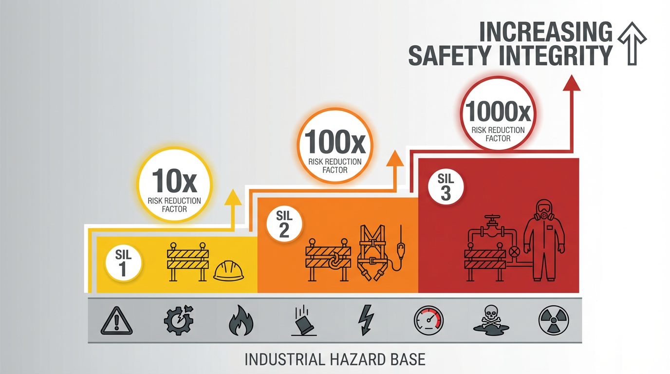
The system must either fail rarely, or fail in a way that still prevents harm. That performance requirement applies to the entire safety loop, not just the PLC that executes the logic.
SIL Applies to the Safety Function, Not the PLC
Both Control Engineering and experienced practitioners on professional forums have emphasized a crucial point: SIL is a property of the Safety Instrumented Function, not of any single device. A SIL 3–certified logic solver does not, by itself, make a SIL 3 safety system.
Every element in the chain contributes to the probability of dangerous failure on demand or per hour.
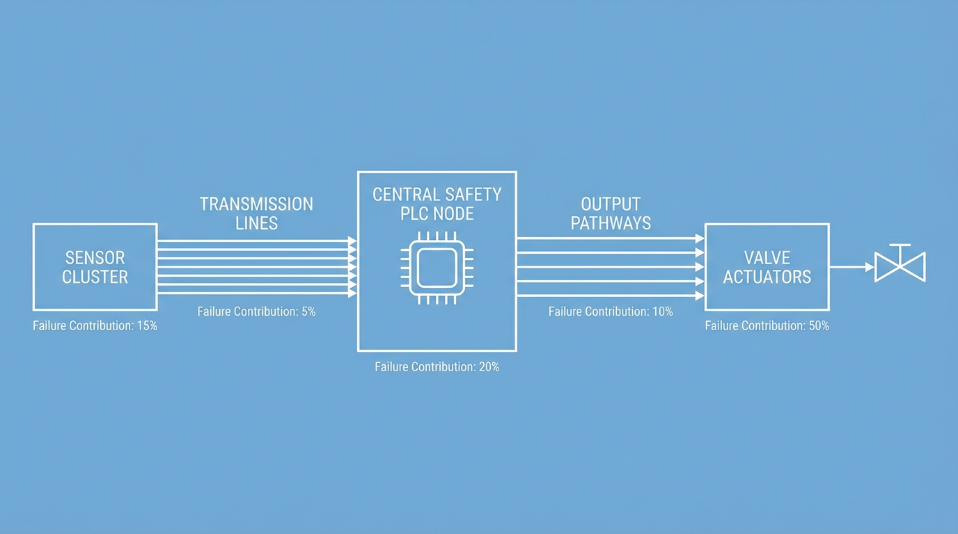
That includes sensors, logic solver, wiring, power, communication, final control elements, human interactions and test strategy. Several sources, including Festo, point out that in many real loops the dominant contribution to failure is in the actuators and valves, not in the PLC.
From a selection perspective, this means that choosing a “SIL 3 PLC” is only one step. The platform has to fit into an overall SIF architecture where the combined failure data for sensors, PLC, and final elements falls inside the SIL 3 band. Failure rate and diagnostic data are summed or combined at the loop level based on the architecture and test intervals.
Confirming You Really Need SIL 3
Before you spend money on a SIL 3–capable safety PLC, you need confidence that SIL 3 is genuinely required. Heating and Process describes SIL 3 demand in process plants as rare and notes that many SIFs end up with SIL 1, with a smaller portion requiring SIL 2. A SIL 3 target should trigger a second look rather than an automatic purchase order.
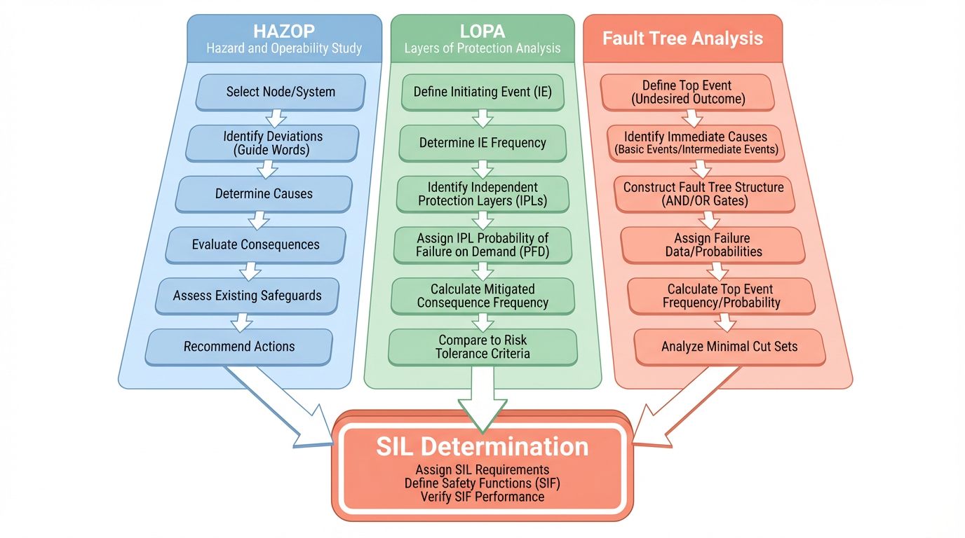
Standards such as IEC 61508 and IEC 61511 require SIL determination to be systematic, not based on experience or rule of thumb. Commonly used methods include Safety Layer Matrix, risk graphs, Layer of Protection Analysis, fault tree analysis and event tree analysis. Heating and Process reports that Layer of Protection Analysis is widely used for large facilities, while fault tree and event tree analysis are favored for complex or high-SIL cases because they can capture dependencies and detailed failure logic. For SIL 3, they recommend reassessing any initial result using fault tree analysis rather than relying solely on simpler screening methods.
Publications from PDF Supply and others underline the same point. SIL targets come out of structured studies such as HAZOP, LOPA or similar methods, and the results are captured in a Safety Requirements Specification for each SIF. You do not decide on SIL by intuition, and you do not pick SIL 3 simply because a hazard feels serious. The methodology forces you to quantify initiating event frequencies, protection layer effectiveness and consequence severity.
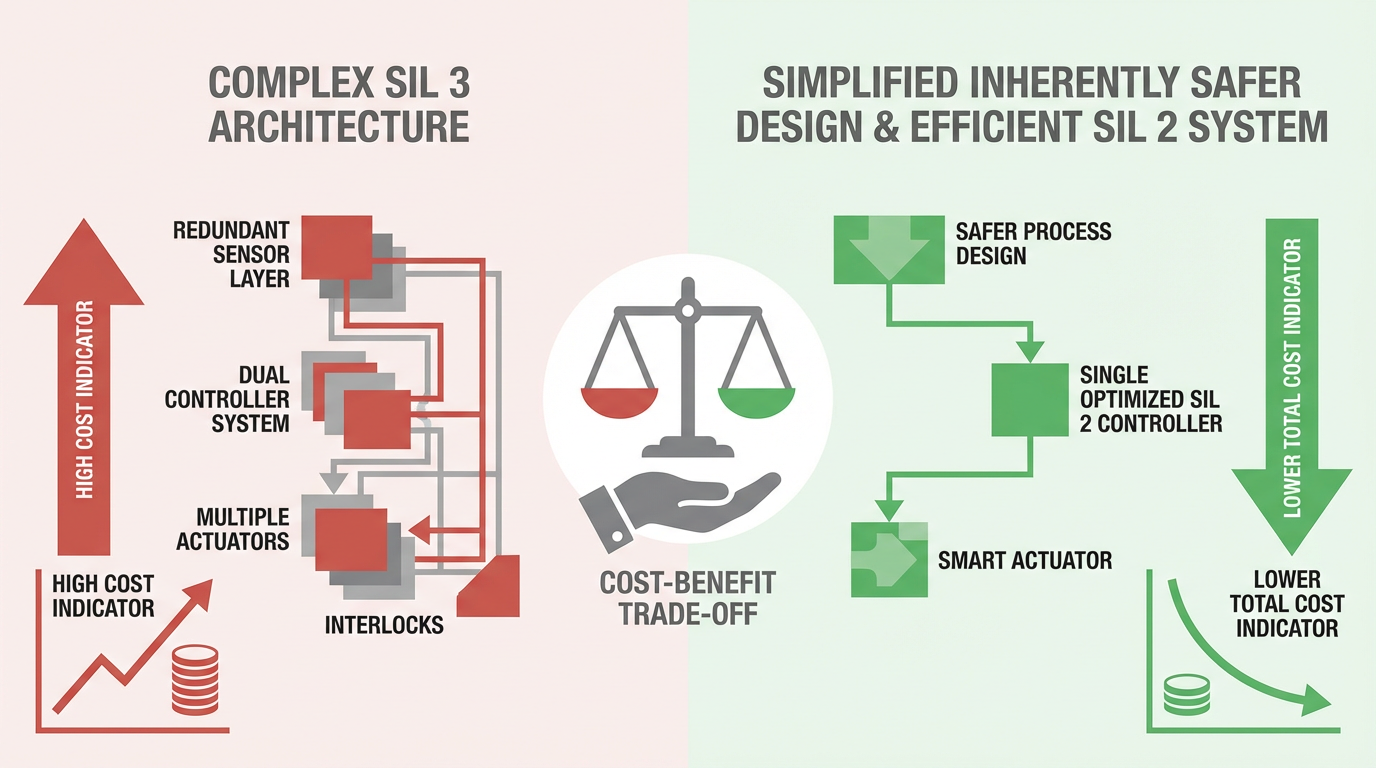
There is also a strong economic argument. Schneider Electric’s functional safety community highlights that SIL 3 is typically the highest level that remains economically feasible for most industrial operations. It is associated with more expensive equipment, stricter design and verification processes and the need for specialized skills. However, when risk studies show SIL 3 is needed, the cost of not implementing it can be much larger in terms of incidents and downtime. The right level is the one that reduces risk to an acceptable band, not the one that looks impressive on a slide.
In practice, on projects where we re-examined an initial SIL 3 assignment with more detailed fault tree analysis and a better model of alarms, operator response and personnel exposure, the target often moved down to SIL 2. Sometimes, as described in case studies in industry articles, redesigning the process or mechanical safeguards reduced the underlying hazard enough that a lower SIL could be justified, and that decision saved substantial capital and lifecycle cost.
What Makes a Safety PLC Different
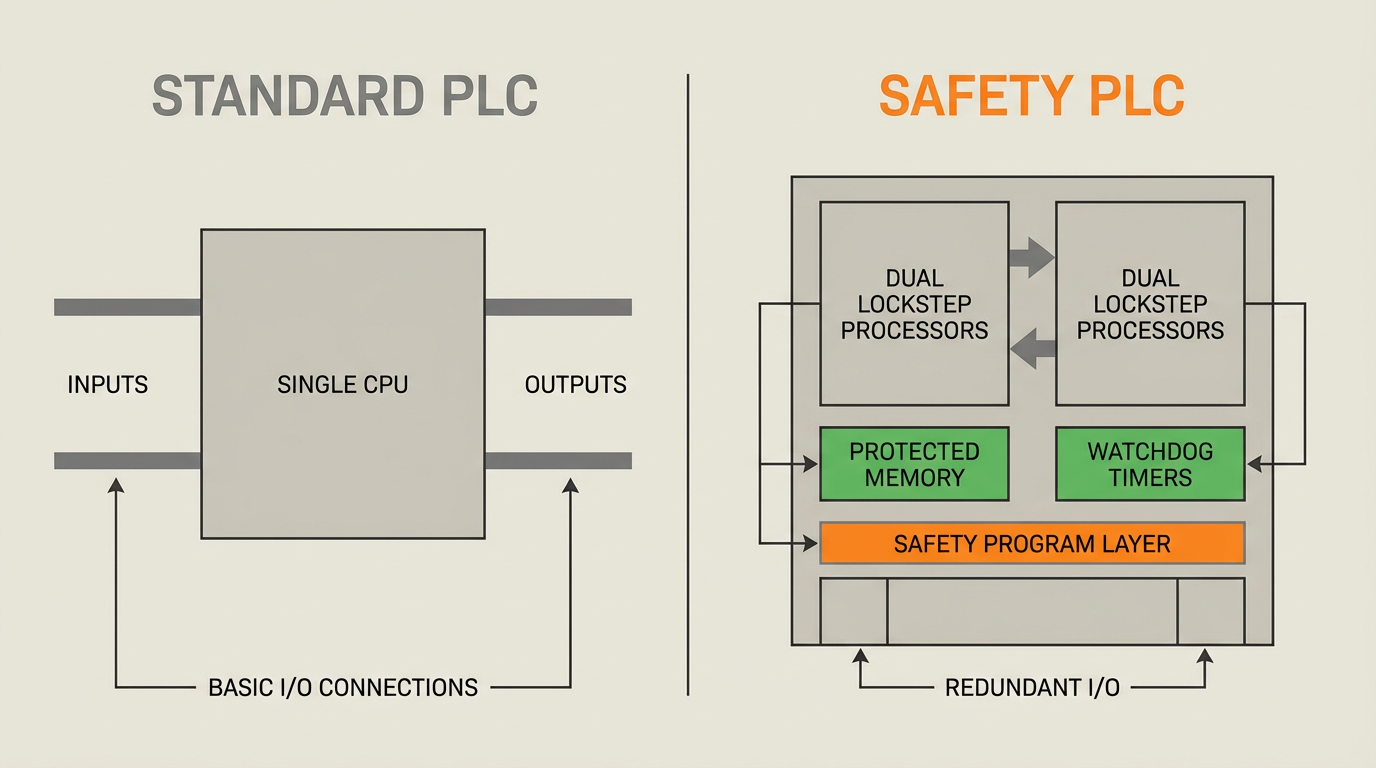
When a SIL 3 target survives this scrutiny, you need a safety PLC that can support it. A safety PLC is not just a standard PLC with a safety sticker. Domain articles, including technical material summarized from Do Supply, describe several key distinctions.
A safety PLC is developed under functional safety standards such as IEC 61508, IEC 62061 and ISO 13849. Both hardware and software go through rigorous processes with defined safety life cycles, verification and validation activities and often third-party certification by organizations such as TÜV or UL. Safety PLCs typically use redundant or lockstep processor architectures, extensive self-diagnostics, protected memories and safety-rated communication paths. They run a dedicated safety program in parallel with the standard control program, with additional checks on program flow and data integrity, and are designed to drive the system to a defined safe state if discrepancies are detected.
Some safety PLCs incorporate enough internal redundancy in a single CPU module that, when used according to the safety manual and the applicable standard, they can form part of a SIL 3 loop without multiple external CPUs. That point is emphasized by practitioners in the Automation & Control Engineering community: minimum hardware architecture requirements vary between standards such as IEC 61511 and IEC 61508, and the vendor’s safety manual defines precisely which architectures are acceptable at which SIL.
Safety PLCs also provide certified safety function blocks for common tasks such as emergency stops, guard doors and two-hand controls. These pre-certified function blocks behave like virtual safety relays, which simplifies engineering and reduces systematic error. Modern systems allow these functions to be configured in a dedicated safety task with strict execution rules and restrictions on what instructions may be used.
| Aspect | Standard PLC | Safety PLC suitable for SIL 2–3 (based on industry descriptions) |
|---|---|---|
| Design standard | General industrial control standards | Developed and assessed under IEC 61508 and related safety standards |
| Architecture | Single CPU, limited diagnostics | Redundant or lockstep CPUs, extensive self-tests, protected memory and watchdogs |
| Program domains | Single control program | Separate safety and standard programs, with safety logic able to override or stop standard control |
| Failure behavior | May fail in-place or trip unpredictably | Must detect a very high proportion of faults and force a safe state in a controlled way |
| Certification | Vendor declaration or basic compliance | Third-party certification for use in SIFs up to a defined SIL, often including safety manuals and data for PFD/PFH calculations |
This is why Control Engineering and other sources state that general-purpose PLCs are only suitable for SIL 1 and that SIL 2 and SIL 3 applications require safety-rated platforms.
Architecture and Hardware Fault Tolerance for SIL 3
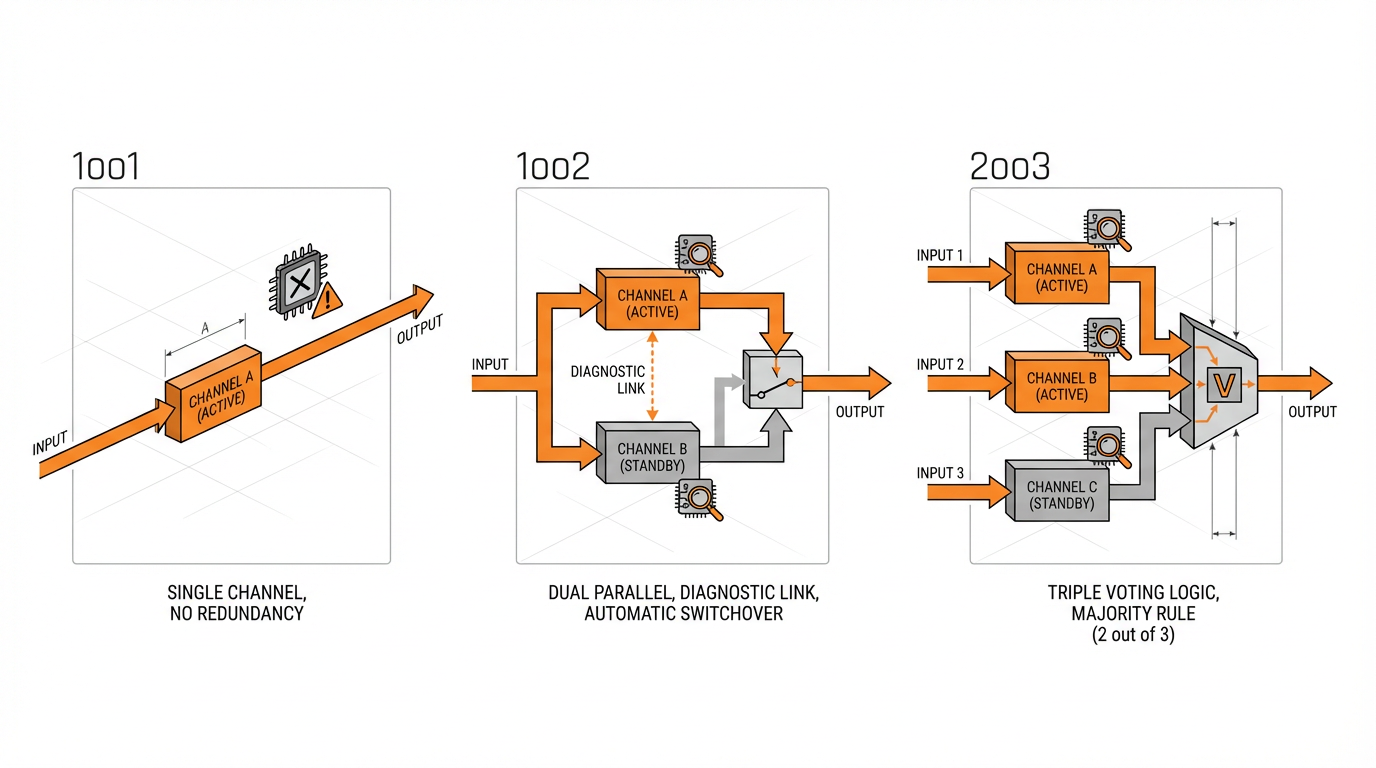
SIL is not only about component quality; it is also about architecture. Control Engineering discusses the concept of hardware fault tolerance, defined as how many hardware failures can occur before the safety function is lost. They note that the minimum fault tolerance requirements increase with SIL. For typical applications, SIL 1 may tolerate zero hardware fault tolerance, SIL 2 requires one and SIL 3 requires two, meaning the system must still be able to perform its safety action even if more than one device has failed between tests.
This leads to familiar high-integrity architectures. Control Engineering describes typical SIL 3 designs using triplicate transmitters, a two-out-of-three logic solver or a one-out-of-two architecture with diagnostics, and either three valves in series or two valves with partial-stroke testing or very frequent full-stroke testing. Festo’s functional safety material explains the same concepts using the shorthand of one-out-of-one, one-out-of-two and one-out-of-three configurations and notes that higher hardware fault tolerance usually means more parallel elements.
The standards allow some flexibility. Control Engineering and Festo both explain that you can sometimes relax hardware fault tolerance requirements by one level when field devices are certified with very low dangerous failure modes and strong diagnostics, backed by detailed failure data. Conversely, if devices have poor or unknown failure characteristics, you may need to increase hardware fault tolerance. What you cannot do is ignore hardware fault tolerance entirely and still claim SIL 3.
Once again, this is a system-level discussion rather than a PLC-only decision. The actuators and valves usually dominate the probability of failure. Festo points out that in a single-channel loop, the largest share of PFD or PFH is often allocated to the final elements. Meeting SIL 3 may demand more valves, more advanced diagnostics and more proof testing, which has a material impact on both capital and operating expenses.
Certification and Independence for SIL 3 Logic Solvers
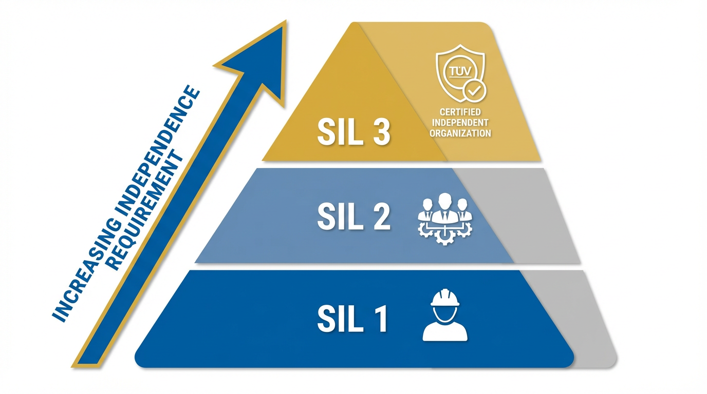
When you are specifically targeting SIL 3, the level of independence in certification becomes critical. Festo’s guidance on IEC 61511 highlights that for SIL 3 and SIL 4, certification must be provided by an independent organization rather than relying solely on the manufacturer’s declaration. For SIL 1, an independent person may be sufficient; for SIL 2, an independent department is expected; for SIL 3 and SIL 4, the requirement escalates to an independent organization.
In practical terms, that means your safety PLC platform should have up-to-date certificates from an independent assessor stating its suitability for use in SIFs up to SIL 3, including the operating modes (low demand versus high demand), architectural constraints and any limitations on programming practices or instruction sets.
Vendor safety manuals spell out what you must and must not do to maintain the certified integrity level.
Automation Ready Panels stresses the value of using TÜV-certified controllers, safety I/O, drives and safety devices when targeting SIL 2 or SIL 3, and recommends working with vendors that can support design, programming and testing of safety PLC systems in line with IEC 61508 documentation requirements. From an integrator’s standpoint, that depth of documentation and vendor support often matters as much as the claimed SIL capability.
Practical Criteria for Selecting a SIL 3 Safety PLC
Once the risk assessment justifies SIL 3 and you understand the architecture you will need, you are ready to narrow down platforms. In real projects, the decision rests on several interlocking criteria rather than any single checkbox.
Alignment with the Applicable Standards
The first question is which standard governs your safety function. For process industry systems, IEC 61511 is usually the main standard, building on IEC 61508. For machinery, IEC 62061 and ISO 13849 are dominant, with IEC 62061 now harmonized in Europe as EN IEC 62061. Pilz notes that the newer edition of IEC 62061 requires a formal Safety Requirements Specification for each safety function and offers more detailed provisions for safety-related application software. It also allows the use of subsystems developed under other safety standards, as long as the overall SIL target is still met.
Forum practitioners have observed that IEC 61511 sets slightly more restrictive hardware architecture requirements than IEC 61508. That means a given safety PLC might be acceptable for SIL 3 under IEC 61508 but need additional redundancy or specific architectures under IEC 61511. When you evaluate platforms, you should therefore verify not only that the PLC is certified to IEC 61508, but also that its safety manuals and application examples address your sector-specific standard.
Proven SIL 3 Capability in the Role of Logic Solver
Next, confirm that the platform is certified as a logic solver up to SIL 3 for the demand mode you intend to use. Certification should cover the PLC hardware, operating system firmware and programming environment. It should supply the data you need to perform PFD or PFH calculations for your SIFs, including failure modes, safe failure fraction and diagnostic coverage.
Automation Ready Panels uses an example of a SIL 3–rated controller achieving dangerous failure rates below about 10^-7 per hour when configured correctly, highlighting how such devices can support high-risk processes when integrated with compatible safety networks and field devices. The specific numbers are less important than the fact that you can obtain credible, third-party-verified data that fits inside the SIL 3 bands defined in the standards and in sources such as Heating and Process.
Architecture, Redundancy and Availability
A SIL 3–suitable safety PLC must offer architectures that match your hardware fault tolerance and availability targets. Industry experience, reflected in Control Engineering and practitioner forums, shows that some manufacturers build redundancy into a single processor module so that it can be used in SIL 3 applications with a single physical CPU, provided other conditions are met. Others require multiple CPUs in redundant or voting configurations.
The decision to add more redundancy than the minimum required for SIL is often driven by availability rather than safety alone. A one-out-of-two or two-out-of-three architecture can deliver both the required risk reduction and higher uptime by allowing maintenance or single failures without losing the safety function. As an integrator, you need to verify that the PLC family provides the options you need, from redundant CPUs to safety-rated network modules, in a way that is compatible with your chosen SIF architectures.
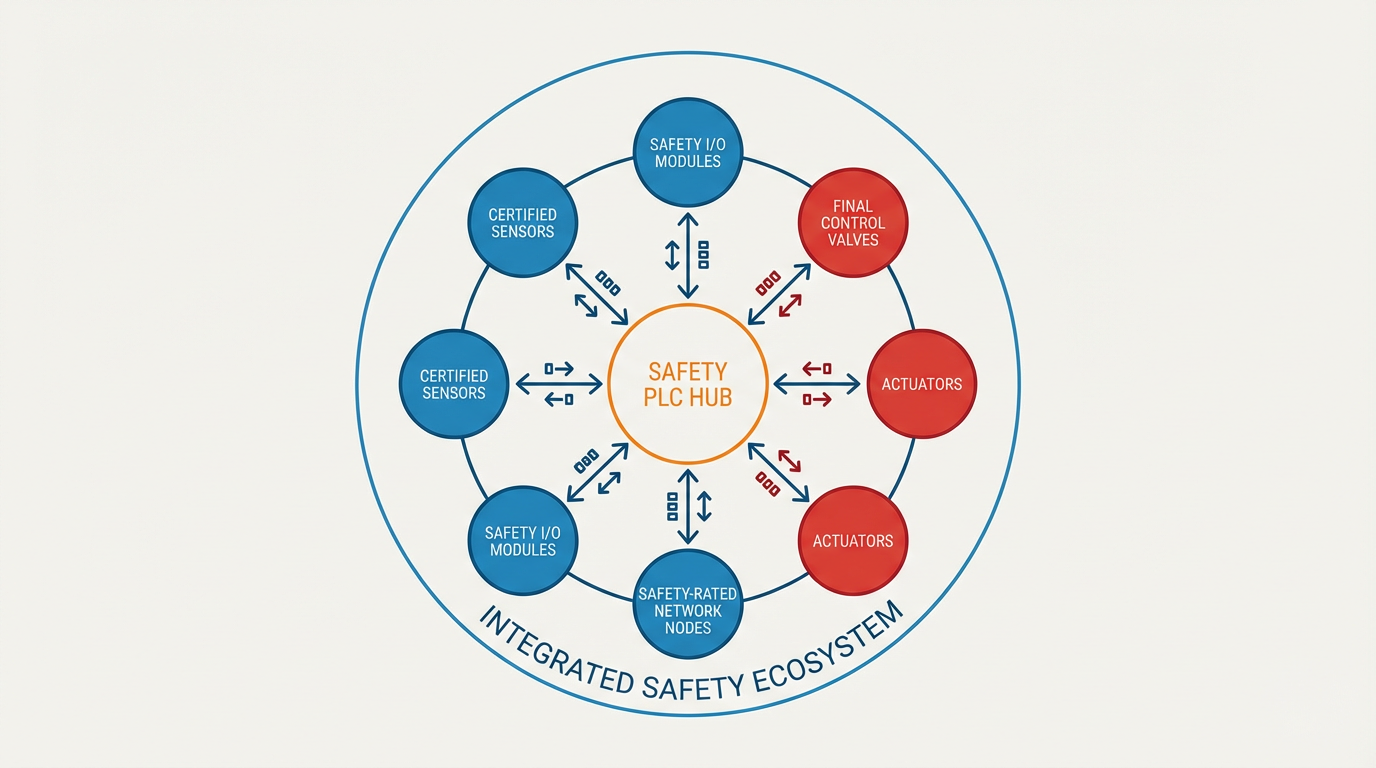
Safety I/O and Field Device Integration
Selecting the PLC in isolation is a recipe for trouble. You need a coherent ecosystem of safety I/O modules, networks and field devices. Festo emphasizes that all failure probabilities used for SIL verification come from manufacturer declarations or certificates, and that integrators must sum these to obtain the total PFD or PFH for a safety function. They also highlight that actuators often dominate the risk profile in single-channel loops.
Automation Ready Panels describes practical SIL 3 implementations using a safety controller with safety-rated discrete inputs for emergency stops and safety contactors that provide feedback signals to the PLC for fault detection and safe shutdown. They also point out the use of safety networks such as CIP Safety over Ethernet/IP to connect safety devices and drives.
From a selection standpoint, you should look for a safety PLC platform that offers certified safety I/O for the signal types you need, supports the safety communication protocol appropriate for your plant and works seamlessly with certified sensors and final elements from the same or compatible vendors. The ability to obtain consistent, reliable failure data for all these components is as important as the PLC itself.
Diagnostics, Proof Testing and Maintenance Support
Achieving and maintaining SIL 3 is not a one-time event. It involves regular proof testing and ongoing monitoring. Heating and Process notes that SIL 3 proof tests are typically more frequent and longer than for SIL 1 functions because of the greater number of elements and the tighter performance band. They suggest that intervals of roughly once per year may be needed, depending on proof test coverage.
A good SIL 3–capable safety PLC should therefore offer strong diagnostics and testing support. That includes built-in self-tests, detailed status information for safety I/O, time-stamped event logging, support for partial-stroke testing of valves through safe output patterns where relevant and tools to simulate or test safety logic without jeopardizing production. Platforms that integrate with calculation and verification tools, such as those mentioned in Automation Ready Panels’ description of SIL verification workflows, make it easier to prove compliance and to update calculations as equipment ages or test intervals change.
From a project partner’s perspective, I always ask how easy it will be for maintenance teams to see why a safety function has demanded or failed a test and how straightforward it is to re-validate after changes. The more opaque the diagnostics, the higher the lifecycle cost and the higher the risk of poorly controlled bypasses.
Cybersecurity and Change Management
Modern safety PLCs live on connected networks and store valuable safety logic. Security is therefore part of safety. Material describing HIMA systems, for example, emphasizes defense-in-depth through minimal exposed services, segregation between safety and non-safety networks, physical key switches to block control functions and mechanisms to show program changes via checksums in the control system.
For SIL 3 applications, it is sensible to prefer platforms that offer robust user and role management, clear separation between safety and standard networks, support for firewalls, secure remote access options and clear audit trails for program changes. The programming environment should include change comparison tools and the ability to lock down, review and approve safety logic modifications. Several safety PLC toolchains also leverage standard operating system access controls while adding their own user layers for safety projects.
This is not just an IT concern. Unauthorized or poorly managed changes to safety logic can invalidate your SIL claim and create systematic faults that no amount of redundancy will fix.
Toolchain, Skills and Lifecycle Support
Finally, practical considerations matter. Safety PLCs are more demanding to engineer than standard PLCs. Do Supply’s analysis points out that programming safety PLCs takes more effort and requires adherence to strict standards, but that modern pre-approved safety blocks help. You need to ensure your team or your integration partner is proficient in the chosen platform and understands functional safety concepts.
Pilz’s discussion of IEC 62061 stresses the importance of a thorough Safety Requirements Specification and structured software development. That implies toolchains that support traceability from requirements to code, version control, and verification documentation. Vendor roadmaps and lifecycle policies also matter; a SIL 3 system is typically expected to operate for many years, and you need assurance that the platform will remain supported and that replacements or upgrades will not unexpectedly invalidate your certification basis.
In practice, I favor platforms where the safety system is integrated with the basic automation platform up to the level needed by the application, as Control Engineering recommends for SIL 2. For genuine SIL 3 functions, that integration must not compromise independence or safety, but it can still simplify engineering and maintenance when appropriately segregated.
Common Pitfalls When Choosing a SIL 3 Safety PLC
There are a few pitfalls that come up repeatedly when plants pursue SIL 3 and select safety PLCs.
One common mistake is assuming that buying a SIL 3–certified PLC automatically delivers a SIL 3 SIF. Both Control Engineering and practitioners on control forums warn against this. If your sensors, valves or human procedures are weak links, the overall SIL will be limited by them regardless of how capable the PLC is.
Another pitfall is neglecting human factors. Heating and Process devotes significant attention to team competence, alarm design and personnel exposure when determining SIL 3. If you rely on alarm response as a protection layer, you must realistically account for operator availability, competing alarms and clarity of instructions. Human error in maintenance, calibration and testing can also make SIL 3 unachievable if not properly modeled and mitigated.
Oversimplifying the math is another risk. Heating and Process explicitly cautions that for SIL 3, you must use appropriate field failure data, treat common-cause dependencies, include test unavailability and account for human interactions. Overly optimistic assumptions can produce a theoretical SIL 3 that does not reflect reality.
Finally, some projects push for SIL 3 without fully recognizing the cost of achieving and maintaining it. Schneider’s community notes emphasize that SIL 3 is more expensive to implement and operate due to hardware, procedures and skill requirements. Control Engineering echoes this by pointing out that true SIL 3 architectures involve more devices, more complex testing and more engineering effort. In many cases, it is more effective to redesign the process to reduce the inherent risk so that a well-designed SIL 2 system suffices.
A Pragmatic Selection Workflow
When I am engaged as a project partner on a prospective SIL 3 application, the workflow is pragmatic but disciplined. It starts with reviewing the hazard analysis and SIL determination, making sure the methods used are appropriate for SIL 3 and that human factors, alarm response and personnel exposure have been adequately handled. If the SIL 3 target stands after reassessment, we move on to defining clear Safety Requirements Specifications for each SIF, including demand mode, required response time, test intervals and constraints on architectures.
Only then do we shortlist safety PLC platforms that have independent certification as SIL 3 logic solvers for the relevant standards and demand modes. We check that their recommended architectures can satisfy hardware fault tolerance requirements within the constraints of the plant. Together with the owner and vendors, we select compatible safety I/O, networks, sensors and actuators for which failure data and certificates are available and start building up PFD or PFH calculations for each loop.
In parallel, we assess diagnostics, proof test strategies and change management capabilities of the toolchain so that maintenance teams can own the system over its life. Throughout this process, we keep an eye on cost and complexity and remain open to revisiting the process design if the effort to reach SIL 3 starts to outweigh the benefits compared with a lower SIL and improved inherent safety.
Short FAQ
Do I always need a dedicated safety PLC to achieve SIL 3?
You need a safety-rated logic solver that is certified for use in SIL 3 safety functions. For most practical purposes, that means a safety PLC or equivalent safety controller. General-purpose PLCs are considered suitable only for SIL 1 in guidance such as that from Control Engineering. Some safety platforms integrate safety and basic control in one environment, but the safety portion must still follow the functional safety standards and the vendor’s safety manual.
Can a single safety PLC module ever be enough for SIL 3?
In some cases, yes. Forum practitioners have noted that certain manufacturers build internal redundancy into a single processor module so that, under IEC 61508 or IEC 61511 and within specified constraints, a single module can participate in SIL 3 SIFs. Whether this is acceptable depends entirely on the applicable standard, the vendor certification and the overall SIF architecture, including sensors and final elements. You must follow the safety manual and verify that your field devices and fault tolerance satisfy the SIL 3 requirements, not just rely on the PLC’s certification.
How do SIL and Performance Level relate when choosing a PLC?
For machinery, safety functions may be specified in terms of SIL under IEC 62061 or Performance Level under ISO 13849. Do Supply’s material on safety PLCs notes that many platforms are certified both for SIL and for Performance Level, often targeting SIL 2 or SIL 3 and Performance Level d or e. When selecting a PLC, ensure that its certifications cover the standard and metric your machinery risk assessment uses and that the vendor provides clear guidance for designing functions that simultaneously meet the required SIL or Performance Level.
Is aiming for SIL 3 always the safest choice?
Not necessarily. The safest choice is the one that delivers the required risk reduction in the most robust and manageable way. Heating and Process and PDF Supply both describe situations where an initial SIL 3 requirement was reduced after more detailed analysis or after redesigning the process to be inherently less hazardous. SIL 3 is appropriate for specific, high-consequence, high-risk situations and demands corresponding investment in architecture, testing and human factors. When SIL 2 is sufficient and the underlying hazard can be mitigated by design, a well-executed SIL 2 system is often a better long-term solution.
Closing
Selecting a safety PLC for SIL 3 is not a catalog exercise. It is the last link in a chain that starts with disciplined risk assessment and ends with a maintainable, testable safety loop whose real-world performance matches its calculations. If you treat the PLC as the whole story, you will either miss your target SIL or overspend for marginal benefit. If you treat it as one element in a coherent SIL 3 strategy, grounded in the standards and supported by solid data and competent engineering, it can become a reliable partner in keeping your plant safe for years to come.
References
- https://www.plctalk.net/forums/threads/safety-plc-for-dummies.82829/
- https://www.controleng.com/safety-integrity-level-3/
- https://www.heatingandprocess.com/sil3/
- https://zeroinstrument.com/understanding-sil-sis-and-sif-essential-safety-standards-for-automation-engineers/
- https://library.e.abb.com/public/775c7cfcf5ef4ec9881003ac2964b358/3ADR025011B0201_2014-11-21.pdf
- https://www.automationreadypanels.com/plc-systems/sil-safety-automation-ratings/?srsltid=AfmBOop2zCV2KVXj2SHW0os5v2ma8W_N2FKM0kncmDoh18zSGOjCuRD8
- https://control.com/technical-articles/what-is-a-safety-plc/
- https://www.scribd.com/document/414157453/jossbrys-160405090857
- https://www.renesas.com/en/document/whp/functional-safety-industrial-automation?srsltid=AfmBOorCCffgxH35AUqPzSWuvW0bc51Eam6ygL55SF0UQymGGhl_r_Jn
- https://www.dosupply.com/tech/2024/04/27/understanding-safety-plcs-principles-and-applications-in-industrial-automation/?srsltid=AfmBOookM_wyF8r8_FMuXbT-LTQVpWf82ALUe1VgVXntAthUL0qoHh9R
Keep your system in play!
Top Media Coverage
Categories


Related articles Browse All
-
 amikong NewsSchneider Electric HMIGTO5310: A Powerful Touchscreen Panel for Industrial Automation2025-08-11 16:24:25Overview of the Schneider Electric HMIGTO5310 The Schneider Electric HMIGTO5310 is a high-performance Magelis GTO touchscreen panel designed for industrial automation and infrastructure applications. With a 10.4" TFT LCD display and 640 x 480 VGA resolution, this HMI delivers crisp, clear visu...
 -
 BlogImplementing Vision Systems for Industrial Robots: Enhancing Precision and Automation2025-08-12 11:26:54Industrial robots gain powerful new abilities through vision systems. These systems give robots the sense of sight, so they can understand and react to what is around them. So, robots can perform complex tasks with greater accuracy and flexibility. Automation in manufacturing reaches a new level of ...
 -
 BlogOptimizing PM Schedules Data-Driven Approaches to Preventative Maintenance2025-08-21 18:08:33Moving away from fixed maintenance schedules is a significant operational shift. Companies now use data to guide their maintenance efforts. This change leads to greater efficiency and equipment reliability. The goal is to perform the right task at the right time, based on real information, not just ...


- Q&A
- Policies How to order Part status information Shipping Method Return Policy Warranty Policy Payment Terms
- Asset Recovery
- We Buy Your Equipment. Industry Cases Amikong News Technical Resources Why choose us
- ADDRESS
-
 32D UNITS,GUOMAO BUILDING,NO 388 HUBIN SOUTH ROAD,SIMING DISTRICT,XIAMEN
Leave Your Comment