
-
Please try to be as accurate as possible with your search.
-
We can quote you on 1000s of specialist parts, even if they are not listed on our website.
-
We can't find any results for “”.
How to Select a VFD for Variable Torque Industrial Applications
Why Variable Torque Loads Need Their Own VFD Strategy
If you spend enough years around process plants, you learn that “a VFD is a VFD” is an expensive myth. Nowhere is that more obvious than on variable torque loads: centrifugal pumps, fans, blowers, and similar fluid-handling equipment. These are the drives that quietly keep buildings conditioned and product moving, and they are also where most of the real energy savings are hiding.
Several independent guides, including work published by Control Engineering and a number of pump-focused application notes, converge on the same point: when you apply variable frequency drives correctly on variable torque services, you can cut motor energy use dramatically, often on the order of tens of percent. One pumping guide notes that pumping systems can represent roughly 20–30% of a typical industrial facility’s electrical consumption, and that putting VFDs on the right variable-flow services is one of the most effective efficiency upgrades available.
The catch is that “correctly” is doing a lot of work in that sentence. Over the years I have been called in after VFD retrofits that never delivered the promised savings or introduced new control problems, and the root cause is almost always a selection that treated a variable torque pump or fan like a generic motor. In this article, I will walk through a practical, field-tested way to choose VFDs specifically for variable torque industrial applications, drawing on guidance from ISA, Motion Industries, Invertek Drives, and others, but translated into the realities of commissioning and keeping these systems running.

How a VFD Behaves on a Variable Torque Load
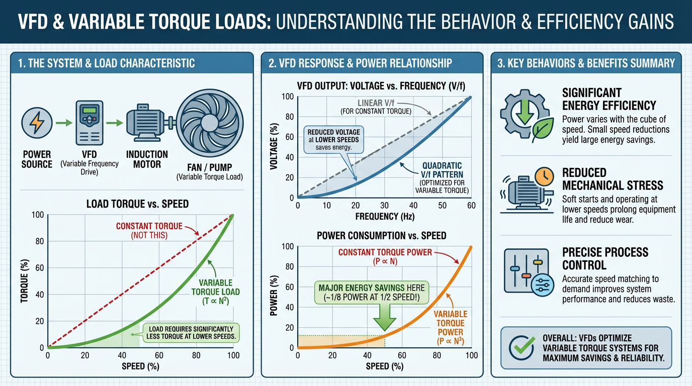
Modern VFDs, as described in resources from Electrical Engineering Portal and Control Engineering, all share a common architecture. The incoming AC mains is first rectified to DC in a converter stage, passed through a DC bus that smooths and stores energy, and then synthesized back into a controlled AC waveform by an inverter that switches power devices such as IGBTs. By varying the output frequency and voltage, the drive adjusts motor speed and torque.
On a fluid load such as a fan or centrifugal pump, the mechanical behavior is very different from a conveyor or hoist. A widely cited VFD selection guide explains that fluid loads have torque roughly proportional to the square of speed, and power proportional to the cube of speed. That relationship is why a small reduction in speed can translate into a large reduction in power. A Control Engineering overview reports that HVAC systems can see up to about 50% energy savings, and centrifugal pumps up to about 60%, when VFDs are used to match speed to demand instead of throttling at full speed.
That cube relationship cuts both ways. If you allow a pump or fan to run over base speed, power demand can rise very quickly, which is one reason most VFD application notes for fluid loads recommend avoiding significant over‑frequency operation unless the pump and motor manufacturers have explicitly approved the higher speed.
Start With the Load: Torque, Static Head, and Rangeability
Every good VFD selection starts with the mechanics. Multiple technical sources, including GoHz’s VFD selection guide and ISA’s “Ask the Automation Pros” discussion, emphasize that you must understand the torque–speed and system-head behavior of the load before trying to pick a drive.
Variable torque loads are those where torque rises with speed. Fans, centrifugal blowers, and centrifugal pumps are the classic examples. Starting torque demands are comparatively modest, and overload requirements are usually lower than for a constant-torque conveyor or extruder. That is why many manufacturers offer “pump and fan” or variable-torque drive families with overload capabilities tailored to this profile, instead of the heavier overload expected for industrial constant-torque drives.
For pumps in particular, the interaction between the pump curve, static head, and motor slip matters for how far you can actually turn the speed down. In an ISA discussion on VFD rangeability, Greg McMillan explains that in an induction motor, the rotor always lags behind the synchronous stator field by an amount called slip. Slip, together with static head, sets a practical floor on controllable speed. Under favorable conditions with little static head and good slip control, he notes that a drive with closed-loop slip control can achieve a usable speed range on the order of 80:1, which is comparable to a magnetic flowmeter’s rangeability. However, when static head is more than about 30% of the total system head at full speed, the minimum controllable flow collapses and overall rangeability can fall to roughly 2:1 regardless of how sophisticated the drive is.
That has major implications for selection and expectations on variable torque pump systems. If your pump is operating near a tall static head, you should not expect a VFD to give you smooth control down to a tiny fraction of design flow. In those cases, some ISA contributors even point out that a properly designed control valve can have better effective rangeability than a VFD, despite the lower energy efficiency.
Selecting a Drive Family: Constant Torque vs Variable Torque Ratings
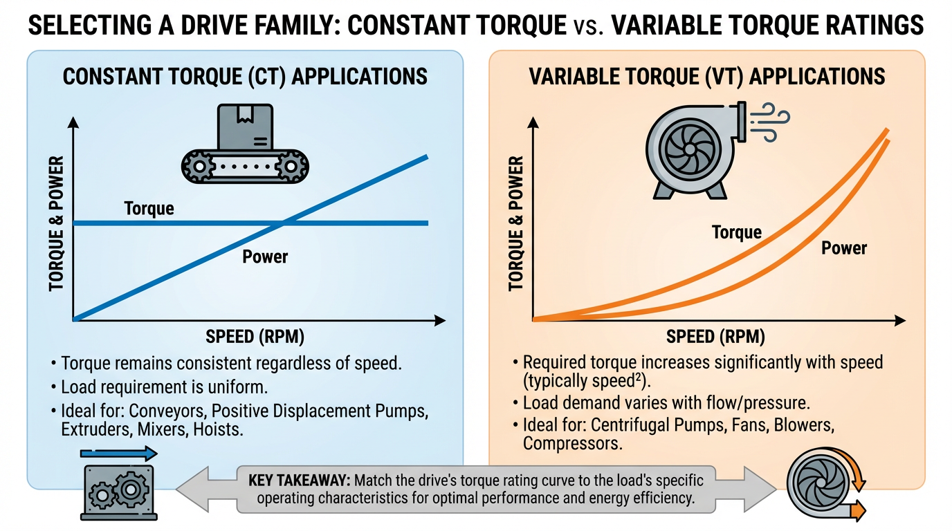
Most major VFD vendors now publish separate families or duty classes for “industrial” (constant-torque) and “pump and fan” (variable-torque) applications. Guidance from Invertek Drives and HVAC-focused sizing notes based on the National Electrical Code explain why.
Industrial or constant-torque drives are designed to deliver high torque across the speed range and to tolerate higher overload, because conveyor drives, mixers, and hoists need strong low-speed torque and may see frequent hard starts. Overload capability in this class is typically around 150% of rated current for a defined duration. An HVAC-centric example from FlowTech discusses an ABB drive that can supply its rated current continuously, about 110% for one minute every ten minutes, and up to about 135% for short transients, with an overcurrent trip limit around 350%. These headroom figures are there to handle belts breaking free, shock loads, and process upsets.
Variable-torque pump and fan drives assume a gentler life. The torque requirement at low speed is much lower, and overload demands are modest. That allows the manufacturer to optimize them for energy efficiency and cost, with lower overload ratings and variable-torque‑specific functions such as cascade control, pressure regulation, and sleep modes. As Invertek’s guidance puts it, for most pump and fan duties where high low-speed torque is not needed, a pump and fan drive is the right choice; positive displacement pumps or compressors that do need high torque at low speed still belong on an industrial drive.
From a selection standpoint, you want to be very clear which duty class the application really needs. Putting a constant-torque crusher on a variable-torque drive is asking for overheating and trips. Putting a modest cooling-tower fan on a heavy industrial vector drive is a waste of money and tends to make setup more complex than it needs to be.
Voltage, Current, and Horsepower: Sizing for Variable Torque Loads
Across multiple sources, including DoSupply’s VFD selection guide, Inverter selection notes from Invertek, and GoHz’s drive selection article, there is strong agreement on one point: size the VFD by current, not just horsepower.
The motor nameplate still matters. You need to match the drive’s voltage class to the supply and motor, whether that is 208 V, 230/240 V, or 460/480 V at low voltage, or a medium-voltage level. However, the most reliable way to ensure the drive can handle the job is to compare the motor’s full-load amps (FLA) to the drive’s continuous current rating. Several sources recommend choosing a VFD with an amp rating slightly above the motor’s FLA, especially on heavier-duty applications, as a straightforward way to increase reliability and reduce the need to upsize later. A generic example given by GoHz is a 10 hp motor drawing about 15 A being paired with a 10 hp VFD rated at around 17 A; the critical point is that the drive’s output current must exceed the motor’s operating current.
Standards-based HVAC guidance that interprets the National Electrical Code adds one important nuance: when a VFD carries a horsepower rating, the code requires that the drive’s hp rating at the supply voltage must be at least equal to the motor’s hp, even if the drive’s current rating would be sufficient for a higher-efficiency or lightly loaded motor. In practice, this means that for code-compliant installations you often end up matching both hp and FLA rather than downsizing purely on current.
On the low end, DoSupply’s guidance notes that single-phase input drives are generally practical only up to about 3 hp at 230 V. Above that, most variable torque fans and pumps should be powered from a three-phase input. When a three-phase motor is fed from a single-phase supply, the drive typically needs to be sized for roughly twice the motor FLA to handle the additional current stress, which is another reason it is worth getting the supply arrangement clear early in the specification.

Low Voltage vs Medium Voltage on Variable Torque Loads
Most building-scale fans and pumps use low-voltage drives, but larger process pumps and air movers move quickly into medium-voltage territory. Electrical Engineering Portal’s discussion of low-voltage versus medium-voltage VFDs emphasizes that medium-voltage drives cannot simply be treated as scaled-up low-voltage units. Insulation stresses, cabling, and converter topologies differ significantly.
A medium-voltage VFD overview from EMA, a firm specializing in drive applications, notes how the market expanded after key patents expired, bringing more brands and more ways to mis-specify a drive. They highlight that footprint becomes a critical parameter in retrofits; some compact drives fit existing rooms but are harder to service and cool, while slightly larger enclosures can be easier to maintain. More importantly, they stress that for medium-voltage VFDs you should treat an input disconnect as effectively mandatory from a safety and protection standpoint, even if it is sold as an option.
That same source dives into the internal capacitor technologies used on medium-voltage drives. Electrolytic capacitors are cheaper but have shorter usable life on the order of seven to ten years. Film capacitors cost more but can run closer to fifteen years, and oil-filled units, while bulky and expensive, may reach twenty to thirty years. For critical variable torque services where downtime is costly, investing in longer-life capacitors can reduce maintenance outages over the drive’s life.
For remote pumps with long motor leads, EMA stresses the importance of drive output topology. When cable runs exceed roughly 300 ft, higher-level inverter designs that produce a more sinusoidal output, such as seven- or nine-level topologies, tend to be much more motor-friendly than simple three-level outputs and may avoid the need for additional filters. On extremely long runs, however, they note that a sine-wave output filter is usually required regardless of the drive brand or topology.
Finally, they echo the low-voltage guidance on sizing: drives should be selected based on full-load amps, not just nominal horsepower, and you must be clear whether the manufacturer’s ratings are for variable torque or constant torque. Using a medium-voltage drive rated only for variable torque on a genuinely constant-torque application can render an expensive piece of equipment unsuitable for service.
Control Methods for Variable Torque Applications
Once you know the mechanical and electrical envelope, the next key choice is how the drive controls the motor. A Motion Industries technical brief on motor control methods and Emotron’s explanation of VFD types describe three main control approaches relevant to AC drives: simple scalar volts-per-hertz (V/f), vector control, and direct torque control (DTC). A Rexel USA note on Rockwell Automation drives adds detail on specific vector implementations such as sensorless vector control and flux vector control.
A concise way to compare their behavior for variable torque loads is shown here.
| Control method | How it works | Strengths on fans and pumps | Limitations and when to move up | | Control method | How it works | Strengths on fans and pumps | Limitations and when to move up | | V/f (volts per hertz) | Maintains a fixed voltage-to-frequency ratio according to a predefined pattern or “curve.” No rotor feedback; output is open loop. | Simple to commission, often described by Motion Industries as “plug-and-play.” Requires minimal motor data, no encoder, and usually no formal tuning. Widely used on fans and centrifugal pumps, including high-frequency applications, and is the only method that can run multiple motors from one VFD when they all share a speed setpoint. Lower wiring and component count reduce installed cost. | Starting torque is limited; Motion Industries cites around 150% of motor torque at about 3 Hz. Shaft rotation is not guaranteed in all edge cases. Speed regulation is modest, on the order of a few percent of maximum frequency, and overall speed range is typically around 40:1. Only one V/f pattern can be active at a time, which limits how easily you can switch between different torque/speed profiles. For tight pressure or flow control, or demanding transients, performance may be insufficient. | | Vector control (including sensorless and flux vector) | Uses a motor model and estimates or measures rotor position to control torque and flux separately. Often requires auto-tuning with accurate motor data. | Provides much better dynamic torque and speed control, especially under varying load. A Rexel USA article notes that sensorless vector control can deliver substantial short-term torque boosts without oversizing the drive, which is helpful for breaking away sticky loads. On variable torque services where process stability is critical, vector control gives more predictable response than simple V/f. | Requires good motor data and successful auto-tuning; if tuning is incorrect, symptoms include high current, low frequency operation, and failure to reach commanded speed. More parameters must be configured, which increases commissioning complexity. Usually limited to one motor per drive. Overkill for straightforward fan or pump duties where only modest regulation is required. | | Direct torque control (DTC) and high-performance vector | Directly controls motor torque using fast sampling and switching logic instead of traditional PWM modulation. Often paired with encoder feedback. | Offers extremely fast torque response and very wide speed range, even at low or zero speed. Emotron and Rexel highlight these modes for cranes, winders, test rigs, and high-performance vertical or tension-regulated drives. On special fluid applications that need very precise pressure or tension control over a wide range, DTC-class systems can provide exceptional performance. | Cost and complexity are higher. Tuning and feedback devices require more engineering effort. Usually reserved for demanding constant-torque or specialty variable torque applications rather than everyday building fans and centrifugal pumps. |
For most industrial fans and centrifugal pumps, a properly configured V/f drive with an appropriate pump or fan curve is entirely adequate. Motion Industries points out that many drives provide preset V/f patterns optimized for common applications, selectable via a single parameter, and also allow custom patterns to be programmed. On more demanding process services where pressure stability, rapid response, or wide turndown are critical, vector control is worth the additional effort, but it should be applied with care and proper auto-tuning as emphasized in Rexel’s guidance.

Programming and Features That Matter on Variable Torque Drives
Choosing the right hardware is only half the battle. A Yaskawa-supported article on programming VFDs for variable-torque applications makes a strong point: even the best drive will misbehave if basic parameters are left at defaults.
At a minimum, you should enter the motor full-load current, verify the rated voltage and speed or pole count, and confirm the run command and speed reference sources. Drives used as protection devices rely on the correct FLA value; if it is left at the factory setting, overload behavior will not match the motor. For most fans and pumps, the default run command (a dry contact) and speed reference (an analog input) are acceptable, but they still need to be wired and confirmed.
Acceleration and deceleration times are particularly important on large fluid loads because they determine how quickly the system ramps to or from full speed. Too aggressive a ramp can cause pressure shocks in piping or nuisance trips from current limits. Too conservative, and the system feels sluggish to operators. The same Yaskawa article points out that minimum and maximum speed limits are also important; for example, you may need a minimum speed to keep fluid moving in a pump to avoid settling or overheating.
Stopping method, usually configured as coast-to-stop by default, is another subtle parameter. On most variable torque applications, a coasting stop is sufficient and avoids regenerating energy back into the DC bus. Where a faster stop is required, you may need to adjust deceleration ramps and consider whether dynamic braking is necessary.
Modern drives also provide auto-restart after power dips or blackouts. By default, this is often disabled for safety reasons. For critical services, enabling an appropriately constrained auto-restart can dramatically improve resilience, but it must be coordinated with process safety requirements and interlocks.
Advanced parameters can further improve reliability. The same Yaskawa piece highlights volts-per-frequency curve adjustments and carrier frequency settings. Tweaking the V/f curve can improve starting behavior or low-speed performance on tricky loads. Carrier frequency influences the smoothness and audible noise of the motor waveform versus switching losses and heating; it is a tradeoff that should follow manufacturer guidance. Over-torque and under-torque alarms based on output current are particularly useful for variable torque drives, for example to detect a broken belt on a fan or a dry-run condition on a pump.
Application-focused VFDs add even more. Invertek’s guidance notes that pump and fan drives may include fire-alarm override functions, emergency modes, and built-in PID algorithms specifically tuned for pressure and flow control. Pumping resources from John Brooks Company emphasize using drive-based PID to hold pressure or level while protecting system components, and supporting multi-pump lead–lag control, duty rotation, and automatic standby.
In all cases, commissioning should end with a deliberate verification stage. The recommended checks are straightforward but often skipped in the rush to hand over a project: briefly bump the motor to confirm rotation direction, correct any reversal by swapping two motor leads at the drive output, verify running current with both the drive’s keypad and an external meter, and confirm that every I/O point wired into the drive behaves as expected. As the Yaskawa and Invertek documents both stress, misconfigured or unverified I/O is a frequent cause of “it just doesn’t work” complaints after startup.
Power Quality, Motor Stress, and Cabling
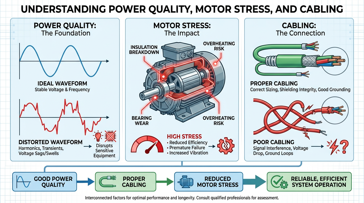
Control Engineering’s VFD best-practices article and Electrical Engineering Portal’s discussion of converter topologies both warn against ignoring power quality and motor stress when specifying drives. All PWM-based VFDs inject some harmonic distortion back into the supply. For many variable torque loads this is acceptable, but at larger sizes or in sensitive facilities you may need drives with active front ends, multi-pulse rectifiers, or external harmonic filters to meet distortion limits. Electrical Engineering Portal describes how combining multiple six-pulse converter bridges and using multi-secondary isolation transformers can create 12-, 18-, 24-, or 36-pulse rectifiers that significantly reduce harmonics.
On the motor side, high dv/dt switching can stress insulation and bearings, especially on longer cable runs. Multiple sources, including Electrical Engineering Portal and ISA contributors, recommend using motor-rated cables with proper shielding, grounding, and sometimes output filters to mitigate these effects. ISA’s list of design and installation best practices for VFD systems specifically calls out using jacketed and shielded cables, keeping VFD power cables in trays separate from instrumentation cables, and considering inverter chokes, isolation transformers, and ceramic bearing insulation where appropriate.
Invertek’s installation guide adds an EMC perspective, noting that drives with built-in EMI filters are usually a better choice than trying to retrofit compliance later, and that screened or armored motor cables grounded at both ends, along with careful cable routing and separation of power and control wiring, are crucial to meeting electromagnetic compatibility requirements.
For variable torque applications in particular, long runs to remote pumps or cooling towers are common. That is where the medium-voltage guidance from EMA about using higher-level output topologies and, when necessary, sine-wave filters becomes especially important.
Commissioning and Loop Tuning with VFDs on Pumps and Fans
Once the hardware is installed and basic parameters are in place, the last piece of the selection puzzle is how the VFD will interact with the control system. The ISA “Ask the Automation Pros” panel offers several hard-won lessons here.
One recurring mistake they describe is using both a VFD and a control valve in separate control loops acting directly on the same process variable, such as level or flow. The result is that the loops “fight” each other. A better arrangement, when both a drive and a valve must exist, is to use the VFD as a valve position controller: adjust pump speed to keep the valve within an optimal opening band, typically around 60–70%, so the valve retains authority while the VFD trims energy use. Even then, the panelists stress that the valve and VFD controllers should have distinct dynamics, with the VFD responding more slowly and based on filtered valve position, so it does not chase every small movement.
At the same time, several practitioners in that ISA discussion argue that if energy efficiency is the primary reason for adding a VFD, and hydraulics permit, pure VFD control without a throttling valve is often the cleanest and most efficient solution. In those designs, with the valve either absent or normally wide open, great care must be taken to understand system hydraulics, static head, and required minimum flows so that the VFD alone can meet the control requirements without damaging the pump.
Loop tuning with VFDs also has its own traps. ISA Fellow Michel Ruel describes how drive limits, such as current limits and acceleration/deceleration ramps, can make the loop appear sluggish for large setpoint changes because the drive is clipping the requested action. If the PID is tuned on the basis of these large-signal dynamics, it may seem fine during big moves but become overly aggressive and oscillatory when the process is near setpoint, where the drive is no longer limited and the apparent process time constant is much smaller. His advice is to tune primarily for small changes and to ensure that drive limit parameters are set in a way that supports, rather than undermines, the intended control performance.
On high static-head pump systems, Greg McMillan’s observations on slip and rangeability come back into play. When static head dominates, both valves and VFDs see their effective rangeability degrade, and the minimum controllable flow becomes dictated more by hydraulics noise and disturbances than by drive capability. For extreme cases, he mentions a proposed but not widely proven strategy of combining a normally wide-open throttling valve with a VFD in split-range, having the valve begin to throttle only after the VFD reaches its minimum speed. Such schemes require careful scheduling of tuning parameters and possibly advanced features like external reset feedback to avoid excessive cycling around the split point.

FAQ: Practical Questions on VFDs for Variable Torque Loads
How low can I safely run a VFD-driven fan or pump?
A selection guide discussed by DoSupply cautions against running motors below roughly 20% of rated maximum speed for extended periods without auxiliary cooling, because self-cooling is usually inadequate and overheating can result. Many variable torque applications do not need to go that low, but if your control strategy calls for deep turndown, you should verify the motor’s cooling arrangement and, as ISA contributors emphasize, consider the impact of static head and slip on the minimum controllable flow.
Do I really need a “pump and fan” drive, or will a general-purpose VFD work?
Invertek and several other manufacturers note that while general-purpose drives can often be configured for variable torque loads, using a pump and fan-class drive simplifies life. These drives are rated and preconfigured for the lower overload and specific functions common to fans and pumps, such as cascade control, sleep modes, and pump protection. For positive displacement pumps or mixed services where high low-speed torque is needed, an industrial or constant-torque drive remains the better choice.
When should I move from simple V/f control to vector control on a pump or fan?
Motion Industries’ overview of control methods suggests that V/f control is adequate and cost-effective for many variable torque applications, especially where tight speed regulation is not critical. If your process demands tighter pressure or flow control, rapid response to disturbances, or wide speed range under varying load, then vector control is worth considering. A Rexel USA article shows that sensorless vector control can provide substantial torque boosting without oversizing the drive, but it requires accurate motor data and successful auto-tuning. For everyday HVAC fans and lightly loaded centrifugal pumps, the added complexity of vector control is often unnecessary.
Closing Thoughts from a Systems Integrator
A VFD on a variable torque load is not just a box that makes motors spin slower; it is a power converter, a control element, and a long-term maintenance commitment. When you match the drive family, current rating, control method, and application features to the real behavior of your pumps and fans, the payback is real: quieter systems, smoother control, and energy bills that finally track what the sales brochure promised. Take the time to start with the load, respect the hydraulics, and configure the drive as carefully as you would a good control loop, and your VFDs will behave like the reliable project partners they were supposed to be.
References
- https://blog.isa.org/ask-the-automation-pros-what-is-the-best-vfd-design-and-installation-plan
- http://www.vfds.org/specifying-sizing-vfd-to-enhance-productivity-642922.html
- https://emainc.net/avoid-these-mistakes-when-selecting-a-medium-voltage-variable-frequency-drive/
- https://electrical-engineering-portal.com/selecting-proper-variable-frequency-drive-vfd-motor-applications
- https://www.gohz.com/vfd-selection-guide?srsltid=AfmBOorOPg5pzXou4zETiPjOF7vZlf3ZOscBzz5FDI2TMWQdtDmpNdpn
- https://www.controleng.com/variable-frequency-drive-advice-best-practices-for-engineers/
- https://www.csemag.com/how-to-select-a-vfd/
- https://darwinmotion.com/blogs/7-considerations-for-selecting-a-variable-frequency-drive
- https://www.flowtechinc.com/sizing-vfds-hvac-applications-based-national-electrical-code/
- https://www.linkedin.com/pulse/best-practices-installing-maintaining-variable-frequency-bsthc
Keep your system in play!
Top Media Coverage
Categories


Related Products
-
 3300 XL 11 mm Proximity ProbesManufacturer: Bently Nevada
 -
 8mm Eddy Current SensorManufacturer: Epro
 -
MetricProximity Probe HousingAssembliesManufacturer: Bently Nevada
-
3300 XL 8 mm Proximity ProbesManufacturer: Bently Nevada
-
32mm Eddy Current SensorManufacturer: Epro
-
Digital Output ModuleManufacturer: ICS Triplex
-
CONTROL BOARDManufacturer: ABB
-
3300 XL 8 mm Proximity ProbesManufacturer: Bently Nevada
-
 POWER SUPPLY MODULEManufacturer: Hitachi
 -
5 mm and 8 mm Standard Mount ProbeManufacturer: Bently Nevada

Related articles Browse All
-
 amikong NewsSchneider Electric HMIGTO5310: A Powerful Touchscreen Panel for Industrial Automation2025-08-11 16:24:25Overview of the Schneider Electric HMIGTO5310 The Schneider Electric HMIGTO5310 is a high-performance Magelis GTO touchscreen panel designed for industrial automation and infrastructure applications. With a 10.4" TFT LCD display and 640 x 480 VGA resolution, this HMI delivers crisp, clear visu...
 -
 BlogImplementing Vision Systems for Industrial Robots: Enhancing Precision and Automation2025-08-12 11:26:54Industrial robots gain powerful new abilities through vision systems. These systems give robots the sense of sight, so they can understand and react to what is around them. So, robots can perform complex tasks with greater accuracy and flexibility. Automation in manufacturing reaches a new level of ...
 -
 BlogOptimizing PM Schedules Data-Driven Approaches to Preventative Maintenance2025-08-21 18:08:33Moving away from fixed maintenance schedules is a significant operational shift. Companies now use data to guide their maintenance efforts. This change leads to greater efficiency and equipment reliability. The goal is to perform the right task at the right time, based on real information, not just ...


- Q&A
- Policies How to order Part status information Shipping Method Return Policy Warranty Policy Payment Terms
- Asset Recovery
- We Buy Your Equipment. Industry Cases Amikong News Technical Resources Why choose us
- ADDRESS
-
 32D UNITS,GUOMAO BUILDING,NO 388 HUBIN SOUTH ROAD,SIMING DISTRICT,XIAMEN
Leave Your Comment