
-
Please try to be as accurate as possible with your search.
-
We can quote you on 1000s of specialist parts, even if they are not listed on our website.
-
We can't find any results for “”.
Servo Drives with Regenerative Braking in 400 V Systems: A Specification-Level Guide
Servo drives have quietly become one of the biggest energy users – and potential energy savers – in modern plants. When you move from low-voltage 48 V platforms to 400 V class systems tied to your facility mains, the stakes go up sharply. Every deceleration on a high‑inertia axis can either come back as useful power on the DC bus or come back to haunt you as overvoltage trips, overheated cabinets, or prematurely cooked braking resistors.
From years of integrating multi‑axis servo systems, I have learned that regenerative braking is not a checkbox feature. It is a design discipline that has to appear explicitly in your 400 V specification: in how you size the supply, how you design the DC bus, how you choose the drive topology, and how you validate the whole thing on the test bench.
This article walks through how regenerative braking works in servo drives, what changes when you are in a 400 V environment, and how to turn that understanding into practical, specification‑grade requirements.
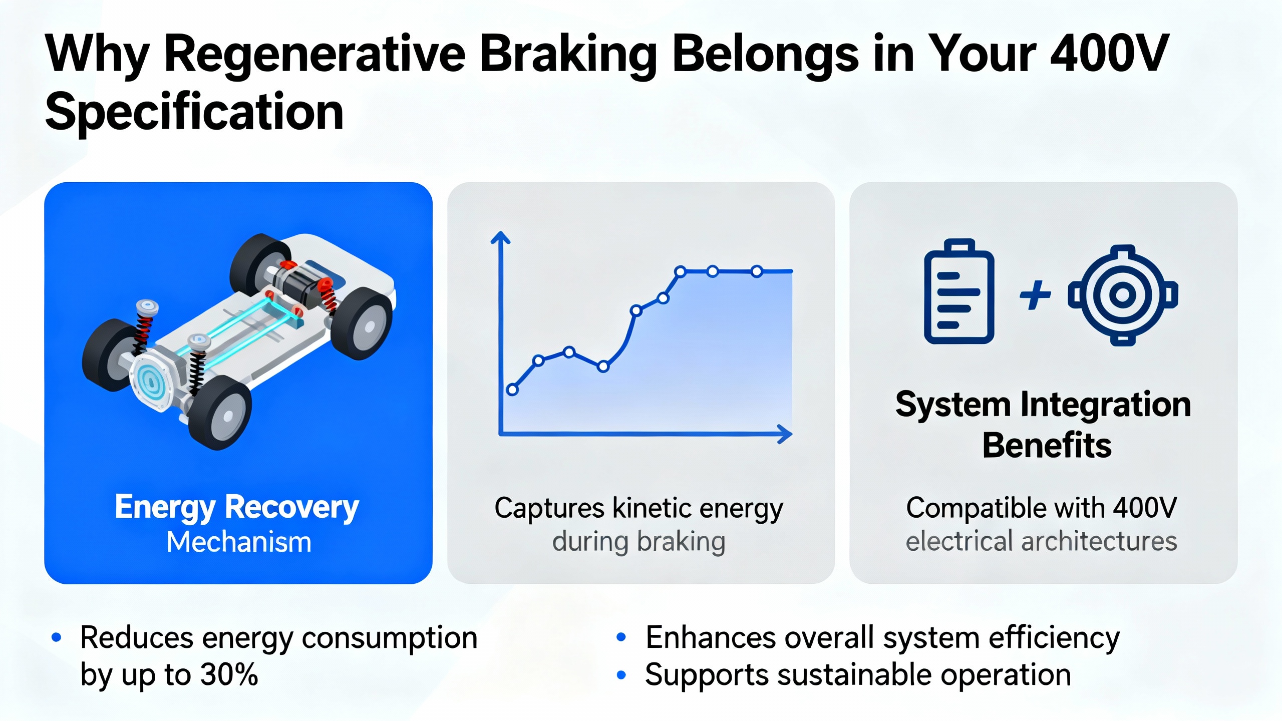
Why Regenerative Braking Belongs in Your 400 V Specification
Regenerative braking simply means using the motor as a generator during deceleration, feeding energy back into an electrical store instead of burning it off as heat. Electric vehicle research summarized by automotive and energy organizations shows that regenerative braking can recover a meaningful fraction of braking energy. One EV manufacturer reports that, depending on conditions, regenerative braking can extend range by roughly 10 to 20 percent, and other engineering summaries collected on ScienceDirect report that rail systems can recover over a third of their traction energy through regeneration. In some tramway installations with reversible substations, careful voltage control has pushed recovery to over 99 percent of the braking energy seen at the traction network.
Laboratory test data from power‑electronics suppliers such as Programmable Power indicates that, in urban driving, regenerative braking efficiency often falls around 60 to 70 percent, dropping to about 20 to 30 percent in highway conditions with fewer stops, and sitting around 30 to 50 percent in mixed conditions. Hybrid vehicle case studies, such as those discussed in manufacturer documentation for the Ford Maverick Hybrid, show that under favorable conditions it is possible to recover well over 90 percent of the available braking energy on individual events.
These numbers come from vehicles and trains, not servo axes. However, the physics is the same. Whenever you have frequent accelerate/decelerate cycles, high inertia, and predictable motion profiles, regenerative braking can reclaim a substantial share of energy that would otherwise be wasted. In an industrial 400 V system that runs around the clock, even modest percentages add up in your electricity bill and in your thermal design.
Just as important, planning for regeneration makes your system more robust. Documentation from Synapticon on servo‑drive power supplies highlights that uncontrolled regenerated energy can drive the DC bus above safe limits, introduce harmonics, and damage components. In high‑inertia or gravity‑affected systems, that is exactly how you end up with nuisance overvoltage trips and unexplained drive failures. A clear 400 V spec for regenerative behavior is therefore both an energy and a reliability requirement.
How Regenerative Braking Works in Servo Drives
Motor and Drive as a Generator
Electrically, the servo motor does not care whether you are driving it or being driven by it. In motoring mode, the drive applies a voltage across the motor windings and current flows in such a way that torque and speed follow your command. In generating mode, the load and inertia drive the rotor faster than the commanded torque would dictate, and the motor’s back electromotive force (BackEMF) pushes current back toward the DC bus.
Motor control literature, such as steady‑state analyses published by Performance Motion Devices, models a permanent‑magnet motor as a BackEMF source in series with resistance and inductance. The effective drive voltage Veff follows the familiar relationship:
Veff = R * i + L * di/dt + Vemf
In motoring mode, Veff helps the BackEMF push current into the motor. In regenerative braking, the situation reverses. The BackEMF dominates, the drive’s effective voltage is set so that it opposes the BackEMF, and the current direction is such that energy flows from the motor back into the DC source. In a battery‑based system this current charges the battery; in a 400 V servo system, it charges the DC bus and ultimately flows either to other axes, to an energy storage element, to a braking resistor, or back toward the grid through a regenerative front end.
The same analysis shows that steady‑state regeneration occurs only in certain combinations of torque and speed where the BackEMF exceeds the effective voltage in the right polarity. Control design matters: if your deceleration commands or current limits never push the system into those quadrants for more than a few milliseconds, you will not see meaningful regeneration, even if the datasheet claims the drive is fully regenerative.
DC Bus, Chopper, and Active Front End
Every 400 V servo system built on modern drives has an internal DC bus. In non‑regenerative drives, that DC bus is usually fed by a simple rectifier and smoothed with capacitors. When you apply braking, the motor pushes current onto that bus and the voltage rises. If nothing is done, the voltage will exceed the continuous maximum rating of the drive, which Synapticon and other vendors distinguish from a brief peak rating that may be allowed for less than a second.
To keep the DC bus within limits, there are three main ways energy is handled.
In drives with only a braking chopper, the drive monitors the DC‑bus voltage and, once a threshold is reached, switches in a power resistor. The regenerated energy is burned off as heat in that resistor. Synapticon’s documentation on servo power supplies notes that this is often required in high‑inertia, low‑friction, or vertical axes where gravity contributes energy during deceleration and the bus can otherwise rise above drive limits.
In drives with a shared DC bus across multiple axes, regenerated energy from one axis can be consumed by others that are accelerating or holding torque. Proper sizing of the total DC‑bus capacitance is critical here. Synapticon points out that DC‑link capacitance is the sum of cabling, drive, and power‑supply capacitors. If it is too small, ripple and harmonics increase and faults become more likely. If it is sized appropriately, it filters ripple and can absorb a portion of the regenerated energy, reducing both power consumption and stress on the supply. Their 48 V SOMANET platform, for example, uses a rule of thumb of roughly 0.5 uF of DC‑link capacitance per watt of drive power and suggests about 470 uF for one node, unless the power supply already brings enough capacitance. While those numbers are specific to a low‑voltage product, the principle scales: more power and stronger regeneration require proportionally more energy storage on the DC bus.
In regenerative drives with an active front end, the drive contains an active supply unit capable of bi‑directional power flow. As described in ABB’s material on regenerative variable speed drives, this lets the drive push braking energy back into the plant supply instead of dumping it into resistors. That same active interface can improve power quality by minimizing harmonics and stabilizing voltage, which helps keep your broader electrical system healthier.
In practice, 400 V servo installations frequently use a combination of these approaches: a shared DC bus to exchange energy between axes, an active front end to return average excess energy to the grid, and a braking resistor sized as a safety valve for cases where the bus would otherwise overshoot.
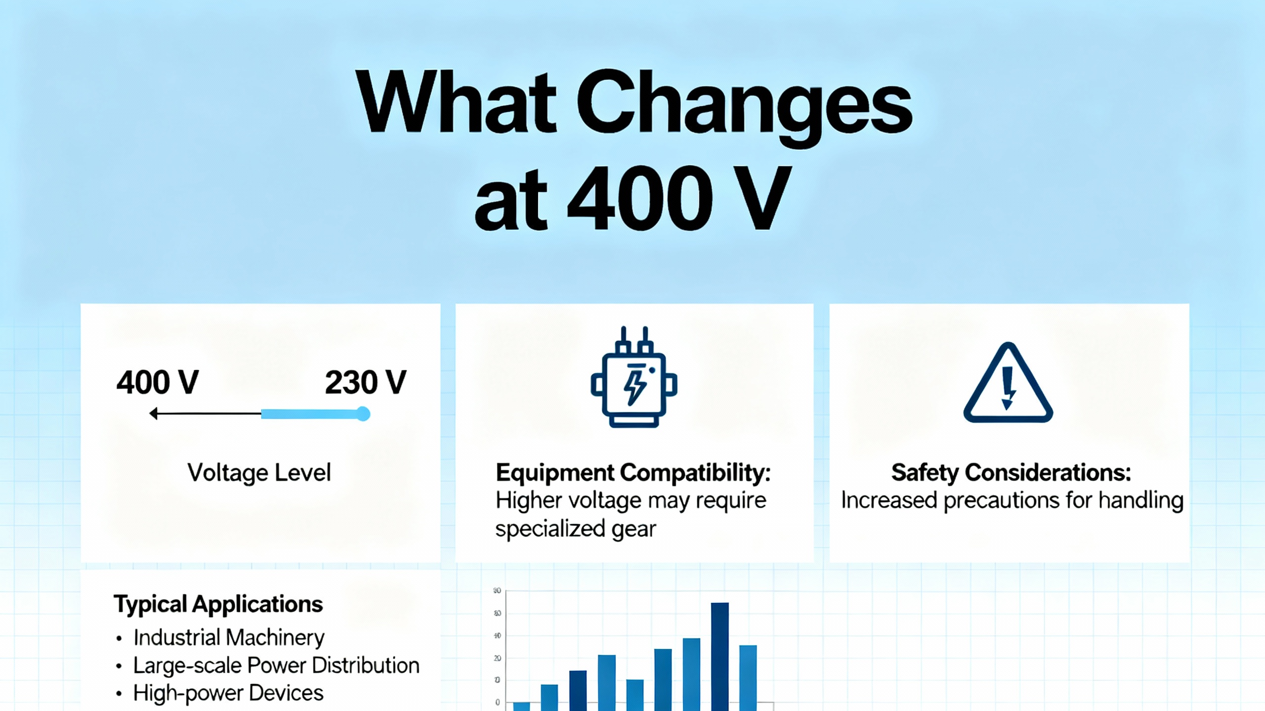
What Changes at 400 V
Moving from low‑voltage (12 to 48 V) servo drives to 400 V class systems changes the consequences of your design decisions rather than the fundamentals.
First, the energy per event is much higher. A high‑inertia axis driven from a 400 V bus stores significant kinetic energy. If you rely purely on braking resistors for every deceleration, you are effectively turning your control cabinet into a space heater. ABB notes that conventional braking with external resistors not only wastes energy but also demands extra cooling capacity. At 400 V, that translates into larger cabinets, more fans, and higher maintenance.
Second, voltage transients are more dangerous. The same Synapticon guidelines that talk about staying below 55 V continuous and 60 V for less than one second on a 48 V platform have direct analogs on 400 V drives, where the ratio between nominal, continuous maximum, and peak maximum must be respected. Allowing a regenerative event to push a 400 V DC bus beyond its peak rating for more than a fraction of a second is a fast way to trigger overvoltage faults or stress components.
Third, at 400 V you are tied to the facility power system. That means your regenerative front ends and shared buses interact with transformers, other variable speed drives, and sensitive loads. ABB emphasizes that regenerative drives, when properly designed, improve power quality by reducing harmonics and stabilizing voltage for neighboring equipment. The flip side is that a poorly specified or misapplied regenerative system can inject noise or backfeed into supplies that are not designed to accept it. Your 400 V specification has to say explicitly whether energy will be pushed back toward the mains and under what conditions, so that the plant power engineer can validate compatibility.
Finally, safety at 400 V is unforgiving. Synapticon’s recommendation on low‑voltage systems to treat most servo application supplies as PELV rather than SELV once connected to earth is a reminder that real machines rarely match ideal lab isolation. In 400 V designs, protective earthing, clear protective extra‑low voltage boundaries, and safe discharge of DC‑bus capacitors during service all become central to the specification.
Electrical Requirements to Put in a 400 V Regen Servo Spec
When I am asked to help write a servo‑drive section for a 400 V machine specification, I make sure several electrical topics are addressed in plain language so that purchasing, safety, controls, and power engineers are all aligned.
The first topic is the supply and regeneration topology. The spec should state whether the servo system is allowed to feed energy back to the plant supply or whether regenerated energy must be handled entirely within the drive cabinet. If feeding back is allowed, the spec should call for drives with an integrated regenerative supply unit similar to the active front ends described by ABB. If feeding back is not acceptable, the spec should require braking choppers and resistors sized to absorb worst‑case braking energy without exceeding their thermal limits, with clear duty‑cycle assumptions.
The second topic is DC‑bus voltage limits and energy storage. Vendors should be required to declare the nominal DC‑bus voltage, continuous maximum bus voltage, and permitted peak voltage and time. Your spec should state that regenerative events must not rely on spending significant time above the continuous maximum and that the system must handle the worst‑case deceleration profile without bus overvoltage trips. The spec can also call out that DC‑link capacitance must be sized to keep ripple within the drive manufacturer’s recommendations and to absorb a defined fraction of regenerative energy. It is entirely reasonable to reference vendor sizing rules, such as the 0.5 uF per watt rule that Synapticon documents for one of its nodes, with the caveat that the drive supplier must confirm appropriate values for the 400 V platform being proposed.
A third electrical topic is braking resistor and chopper design. The spec should describe the types of axes that will generate large regenerative pulses, such as long horizontal gantries decelerating heavy tooling or vertical axes where loads tend to pull the motor during braking. For those axes, the drive vendor should provide calculations for resistor ohmic value, peak power, and energy capacity based on the defined motion profile. Synapticon’s example of a SCARA robot, where realistic motion reduced required supply power from a naive 4 kW to around 2.4 kW including margin, illustrates why real motion profiles and duty cycles must drive these calculations in 400 V systems as well.
Finally, the spec needs to address multi‑axis DC‑bus sharing. In a 400 V system, common DC buses are almost always beneficial for regenerative braking because they let one axis’ braking feed another axis’ acceleration. Synapticon’s guidance on sizing the supply based on the subset of axes that can be simultaneously near their peak power is directly applicable here. The spec should define which axes share a bus, what simultaneous loading patterns are plausible, and how regenerated energy will be distributed across the system.
A concise way to capture these design choices during a review is to walk through a simple comparison table like this:
| Approach | Where Energy Goes | Typical Use Case | Main Benefit | Main Drawback |
|---|---|---|---|---|
| Braking resistor only | Heat in cabinet resistor | Simple retrofits, supply cannot accept backfeed | Simple, predictable, low impact on mains | Wasted energy, extra heat and cooling |
| Shared DC bus | Other axes and bus capacitors | Multi‑axis robots, gantries, transfer lines | Better internal energy reuse | Needs careful bus sizing and fault coordination |
| Active regenerative front end | Back into plant power system | Lines with frequent braking, energy focus | Lower net energy use, better power quality | Higher upfront cost, requires mains integration |
| DC‑bus energy storage modules | Local capacitors or ESS | Systems with poor overlap between axes | Captures energy even when others are idle | Added components, sizing and safety complexity |
The numbers stay out of the table and go into vendor calculations and data sheets, but this structure ensures everyone understands the options.
Servo Motors, Brakes, and Their Role in Regenerative Braking
Regenerative braking is primarily an electrical and control phenomenon, but motor and brake selection determine whether your mechanical system cooperates.
Servo motor selection guidance from motion‑control vendors such as Advanced Motion Controls and others consistently emphasizes defining the motion profile first. You need to know the positions, speeds, accelerations, and cycle times; from there you determine continuous torque, peak torque, and speed range. That same profile also defines the regenerative energy you must manage, because every rapid deceleration of a high‑inertia load pushes energy back into the DC bus.
Inertia matching also matters. When the load inertia is very high relative to the motor’s rotor inertia, the energy stored during motion is correspondingly high. Manufacturers commonly recommend keeping the inertia ratio within a range such as roughly five to ten to one, or taking extra care with tuning and gearing when you go beyond that. From a regenerative perspective, a very high inertia ratio means more stored energy to push onto the DC bus every time you stop, which makes careful braking design and adequate DC‑bus energy handling essential.
Servo motor brakes add a layer of safety but are not a substitute for regenerative braking. Engineering notes from servo brake specialists such as KEB and from servo‑drive vendors point out that these brakes are usually spring‑applied, electrically released devices mounted on the motor shaft. Their primary job is to hold position safely when power is removed, especially on vertical or inclined axes, not to absorb the full kinetic energy of a fast motion. KEB describes how applying DC voltage to the brake coil releases the armature and lets the shaft rotate; removing power lets springs clamp friction surfaces and stop the shaft. These brakes are specified by holding torque and allowed duty cycle, not by their ability to absorb repeated high‑energy stops.
In a 400 V regenerative system, the servo drive and DC bus should handle the dynamic braking through controlled deceleration and energy recovery. The mechanical brake should be engaged once the axis is at rest or at a low speed, or in a power‑loss emergency, to hold the load. Your specification should make that division of responsibility explicit, and brake sizing should be based on static holding torque with a safety margin rather than on absorbing the entire regenerative energy of the motion profile.
Control Strategies: Balancing Energy, Stability, and Mechanical Comfort
Having the right hardware is only half the story. How your servo system commands braking torque determines whether you actually capture energy without abusing the mechanics.
In the electric‑vehicle world, researchers have shown that intelligent control strategies can significantly improve regeneration while maintaining stability and comfort. A study published through PubMed Central describes a control approach that uses game‑theory optimization to balance three objectives: energy recovery, braking stability, and passenger comfort. The authors report that, compared with baseline strategies, their controller improved energy recovery by around 13 to 18 percent in standard driving cycles, kept speed tracking error under about 3 percent, and limited jerk to within a narrow band, which improved ride comfort.
Rail‑traction studies compiled on ScienceDirect describe similar multi‑objective thinking. Engineers optimize braking trajectories and train timetables to increase the overlap between braking and accelerating trains, thereby using more of the regenerative energy internally and reducing stress on substations. Some optimization cases show that, under idealized conditions, up to roughly 96 percent of the initial kinetic energy can be theoretically recovered by carefully shaping braking curves, even though practical savings are smaller due to driver behavior and operational disturbances.
For 400 V servo systems, the same principles apply conceptually. Your control strategy must trade off energy recovery, mechanical stress, product quality, and safety. Aggressive, jerky deceleration may maximize instantaneous regeneration but create unacceptable vibration, product movement, or machine wear. Overly gentle braking may be kind to mechanics but wastes regenerative opportunities and extends cycle time.
From a specification perspective, it is wise to state constraints on deceleration rates and jerk, along with requirements that regenerative braking be prioritized within those constraints. You can also specify that the servo controller should favor electrical braking and use mechanical brakes only for holding or as a last resort in emergencies. That aligns with practices in EVs, where regenerative braking is blended with friction brakes and limited based on system constraints such as battery capability and traction.
Testing and Validating Regenerative Performance at 400 V
A regenerative specification is only as good as the test plan behind it. Power‑electronics suppliers such as Programmable Power describe how programmable DC power supplies, bidirectional power supplies, and regenerative electronic loads are used to test regenerative braking systems under controlled conditions.
In a 400 V servo context, similar tools and methods are applicable. A bidirectional programmable supply on the DC bus lets you emulate the behavior of the plant mains, observe how the drive pushes energy back under different braking scenarios, and check that overvoltage and overcurrent protections behave as intended. Dynamic load simulation on the motor side lets you mimic worst‑case deceleration, emergency stops, and high‑inertia moves without tying up the actual machine.
Programmable supplies with real‑time monitoring allow you to measure voltage, current, and power during braking events and calculate actual energy recovered versus energy dissipated in braking resistors. Programmable Power presents example figures where light braking recovers roughly 10 to 20 percent of available energy, moderate braking recovers about 30 to 50 percent, and hard braking recovers around 60 to 70 percent. Again, these are drawn from vehicle testing, but they give you realistic targets for lab evaluation of drive behavior.
Safety validation is also critical. Programmable sources with built‑in overvoltage and overcurrent protections, such as those described in the Mi‑BEAM series literature, can be used to check that the servo drives shut down safely when presented with fault scenarios and that they do not attempt to push more energy back into the supply than it can accept. For production, a streamlined version of these tests can be turned into an end‑of‑line procedure to ensure each cabinet meets the regenerative performance and safety requirements in your spec.
Energy and Business Impact in 400 V Servo Installations
Most plants do not invest in regenerative servo systems purely for elegance; they do it for energy and lifecycle economics. The experience from EVs, rail systems, and regenerative drive vendors gives a frame of reference.
Engineering reviews collected via ScienceDirect show that urban rail systems with frequent stops can significantly reduce total traction energy consumption by combining regenerative braking, timetable optimization, and, where appropriate, reversible substations or energy storage. Some projects report traction energy savings in the range of about 11 to 23 percent after implementing reversible substations and optimized operations, even when initial predictions were lower. Another study cited in that literature estimates that upgrading substations to reversible thyristor‑controlled rectifiers could pay back within roughly three years through energy savings.
ABB’s qualitative reporting on regenerative drives in industrial applications highlights business outcomes such as lower electricity bills, less cooling infrastructure, more compact installations, and higher uptime due to better power quality. They stress that integrating regenerative functionality directly into the drive reduces external hardware, simplifies design, and cuts maintenance effort.
For a 400 V servo system, the actual energy savings will depend on your duty cycle, inertia, motion profiles, and how well you design the timetable of moves across axes. A lightly‑loaded axis that moves slowly once every few minutes will not justify a sophisticated regenerative scheme. A high‑inertia packaging machine or multi‑axis robot in a three‑shift operation likely will. The specification should therefore tie regenerative features to the axes and motion sequences where the potential is highest, and the business case should be built around those usage patterns rather than a generic percentage.
Short FAQ
Do I still need a braking resistor if my 400 V servo drive is regenerative?
In most real 400 V installations, the answer is yes. An active regenerative front end can handle average energy flow back to the mains, but you still need a local braking path for unusual events such as supply disturbances, simultaneous deceleration of many axes, or cases where the mains cannot accept additional power momentarily. Synapticon’s guidance on high‑inertia and gravity‑affected axes, combined with practical experience, supports treating the braking resistor as a safety valve even in regenerative systems.
How do I avoid DC‑bus overvoltage trips when axes regenerate at the same time?
The solution is a combination of realistic power‑supply sizing, adequate DC‑bus capacitance, proper braking resistor sizing, and motion coordination. As Synapticon’s SCARA example illustrates, sizing the supply based on realistic simultaneous motion, rather than on every axis at full power, gives you headroom. Rail‑system studies on ScienceDirect show that coordinating braking and acceleration events across vehicles increases the use of regenerative energy and reduces stress on substations; the same principle applies when you schedule axis motion in a 400 V servo line.
Is regenerative braking always worth specifying on 400 V servo drives?
Not always, but it is often worth a serious look. For axes with frequent high‑speed moves, significant inertia, or gravity‑assisted motion, the amount of recoverable energy and the potential to reduce cabinet heating usually justify regenerative capabilities. For slow, intermittently used axes, simple braking resistors may be sufficient. A good 400 V specification makes this distinction explicit, requiring regenerative functionality where the duty cycle warrants it and allowing simpler solutions where it does not.
In the end, specifying regenerative braking in a 400 V servo system is less about chasing a headline efficiency number and more about building a system that is electrically stable, mechanically kind, and economically sensible. When those pieces come together, regeneration stops being a buzzword and becomes part of a machine you can sign your name under with confidence.
References
- https://pmc.ncbi.nlm.nih.gov/articles/PMC11080741/
- https://www.limonrobot.com/tips-for-selecting-and-implementing-servo-drives.html
- https://www.a-m-c.com/servo-motor-buying-guide/
- https://www.alphamotorinc.com/about/regenerative-braking-a-key-advantage-of-evs
- https://darwinmotion.com/blogs/how-regenerative-drive-can-improve-inverters-and-servo-motors
- https://www.kpower.com/blog/3426.html
- https://www.linkedin.com/posts/advanced-motion-controls_advancedmotioncontrol-amc-motioncontrol-activity-7339049134206668800-pQN6
- https://ondrive.ca/regenerative-braking-and-servo-motion-systems-smarter-energy-for-smarter-machines/
- https://pctx.us/motor-drive-selection/
- https://www.plantengineering.com/how-motor-controls-impact-everything-from-energy-efficiency-to-costs/
Keep your system in play!
Top Media Coverage
Categories


Related articles Browse All
-
 amikong NewsSchneider Electric HMIGTO5310: A Powerful Touchscreen Panel for Industrial Automation2025-08-11 16:24:25Overview of the Schneider Electric HMIGTO5310 The Schneider Electric HMIGTO5310 is a high-performance Magelis GTO touchscreen panel designed for industrial automation and infrastructure applications. With a 10.4" TFT LCD display and 640 x 480 VGA resolution, this HMI delivers crisp, clear visu...
 -
 BlogImplementing Vision Systems for Industrial Robots: Enhancing Precision and Automation2025-08-12 11:26:54Industrial robots gain powerful new abilities through vision systems. These systems give robots the sense of sight, so they can understand and react to what is around them. So, robots can perform complex tasks with greater accuracy and flexibility. Automation in manufacturing reaches a new level of ...
 -
 BlogOptimizing PM Schedules Data-Driven Approaches to Preventative Maintenance2025-08-21 18:08:33Moving away from fixed maintenance schedules is a significant operational shift. Companies now use data to guide their maintenance efforts. This change leads to greater efficiency and equipment reliability. The goal is to perform the right task at the right time, based on real information, not just ...


- Q&A
- Policies How to order Part status information Shipping Method Return Policy Warranty Policy Payment Terms
- Asset Recovery
- We Buy Your Equipment. Industry Cases Amikong News Technical Resources Why choose us
- ADDRESS
-
 32D UNITS,GUOMAO BUILDING,NO 388 HUBIN SOUTH ROAD,SIMING DISTRICT,XIAMEN
Leave Your Comment