
-
Please try to be as accurate as possible with your search.
-
We can quote you on 1000s of specialist parts, even if they are not listed on our website.
-
We can't find any results for “”.
Siemens 3RW44 Soft Starter Datasheet: Electrical Specifications and Features
If you work around large motors long enough, you learn two things very quickly. First, the electrical system rarely forgives sloppy starting methods. Second, the datasheet is not a formality; it is your survival guide. The Siemens SIRIUS 3RW44 soft starter is a good example. It is a very capable device, but only if you understand what its electrical specifications really mean in the field and not just on paper.
In this article, I will walk through the key electrical specifications and features of the 3RW44 family as they appear in Siemens documentation, and how they translate into real-world behavior. The perspective is that of a systems integrator who has commissioned and troubleshot many of these units on pumps, fans, compressors, and conveyors, including some painful lessons on generators and control power supplies.
What the 3RW44 Soft Starter Is – And What It Is Not
The Siemens SIRIUS 3RW44 is an advanced electronic soft starter for three‑phase induction motors. According to the Siemens 3RW44 operating instructions and SIRIUS catalog information, it uses phase‑controlled thyristors in each phase to ramp motor voltage and limit inrush current. Instead of slamming the motor directly across the line, the 3RW44 brings it up to speed with a controlled, adjustable acceleration and, if needed, a controlled deceleration.
The primary job of any soft starter is to cut starting current and torque compared with direct‑on‑line (DOL) starting. Standard engineering practice, echoed in Siemens and general motor‑starter literature, is that a DOL start pulls about six to eight times the motor’s rated current. With a properly configured soft starter, you can usually bring that down to roughly two to four times rated current. That is still a heavy load on the system, but it is dramatically less brutal on cables, contactors, breakers, and the supply network.
It is just as important to be clear about what the 3RW44 is not. It does not change frequency and it does not provide continuous speed control. It operates at the line frequency, and its job begins and ends with starting and stopping. If your process needs adjustable speed, a variable‑frequency drive (VFD) is the correct tool. If what you need is a clean start and a clean stop for a fixed‑speed motor, especially in the several‑hundred‑kilowatt class, the 3RW44 is a very strong candidate.
Typical applications, as described in the Siemens documentation and reflected in everyday practice, include large pumps, fans, compressors, conveyors, mixers, and similar industrial loads. In pumps, the focus is often on eliminating water hammer. In conveyors and mixers, it is about keeping shafts, gearboxes, and couplings alive for more than one maintenance cycle.
Core Electrical Functions of the 3RW44
From an electrical standpoint, the 3RW44 offers several core functions that you will see reflected in the datasheet and parameter set. These are the functions that shape both current and torque during start and stop, and they are the ones you must understand to select and set the device correctly.
The starting point is the voltage or current ramp‑up. The 3RW44 uses its thyristors to gradually increase the voltage at the motor terminals. In a typical motor application, you choose an initial voltage or current limit, then set a ramp time that fits the driven load. High‑inertia fans and dense‑fluid pumps often need a longer ramp; smaller, lightly loaded machines can tolerate a shorter ramp without excessive current.
Next is the current limit start. Instead of letting inrush land where it may, you can constrain starting current to a target band. General Siemens and soft‑starter guidance suggests that the current limit is typically adjusted somewhere in the range of two to four times the motor’s rated current, depending on line stiffness and load. It is important to remember that this is not a magic knob; if you set the current limit too low for a high‑torque load, the motor may never reach speed and the soft starter will trip on stall or overload.
For loads that require a bit more breakaway torque, the 3RW44 provides a kick‑start function. This briefly applies a higher initial torque before dropping back to the controlled ramp. That can be useful for sticky positive‑displacement pumps or conveyors that tend to settle under load at standstill.
On the stopping side, the 3RW44 supports soft stop profiles, including specialized pump‑stop behavior. Instead of just dropping the contactor and letting water hammer shake your piping, the soft stop function ramps down torque to give the hydraulic column time to slow down. Siemens documentation highlights this as a primary application benefit for pumping systems.
A major practical feature is the integrated bypass contactor. During the ramp, the thyristors carry the motor current. Once the motor is at speed, an internal bypass contactor closes and carries the load, while the thyristors are taken out of the main current path. This is a standard Siemens concept and is emphasized in their soft‑starter literature because it sharply reduces heat dissipation and power loss in steady‑state operation. In practice, a properly bypassed 3RW44 behaves very much like a DOL starter during normal running, which simplifies panel cooling and improves efficiency.
Finally, the 3RW44 incorporates comprehensive motor and system protection. The operating manual describes overload protection aligned to IEC/EN 60947‑4‑2, locked‑rotor and stall detection, phase‑failure and phase‑imbalance monitoring, underload detection, and options for thermistor inputs. In many installations, this allows the soft starter itself to act as the primary motor protection relay, provided it is correctly coordinated with upstream short‑circuit protection.
Key Datasheet Parameters and What They Really Mean
The datasheet for a 3RW44 type, such as the 3RW4444‑6BC35, is dense. It lists voltages, currents, power ratings, duty classes, and many other values. It is tempting to skim for the motor horsepower and move on. That is how systems end up in trouble. The parameters below deserve focused attention.
Line Voltage and Motor Power Range
Siemens catalog information for the SIRIUS 3RW portfolio describes coverage for standard industrial three‑phase motors over a line‑voltage range of roughly 200 to 690 volts at 50 or 60 hertz, extending up into the several‑hundred‑kilowatt class. The 3RW44 family sits at the higher‑performance end of that portfolio. It is designed for sizable motors and demanding applications.
On the datasheet, you will typically see motor power ratings given at standard line voltages and frequencies. These values are guidance, not a substitute for checking motor nameplate current. Two motors with the same rated power at different efficiencies and power factors can draw different currents. Experienced integrators treat the kW/horsepower figures as a rough screening tool and then always validate against the rated current values.
When you are working on multi‑voltage systems or retrofits, pay close attention to the line‑voltage range for the specific 3RW44 variant. Attempting to run at the edge or beyond that range, or mismatching a line designed for one voltage with a starter configured for another, can result in nuisance trips at best and premature equipment aging at worst.
Rated Operational Current and Starting Current
The rated operational current is the anchor of any soft‑starter selection. The Siemens manual and catalog tables provide the permissible motor power for each device size, but selection is fundamentally done by motor rated current, taking the application duty into account.
Standard soft‑starter practice, supported by Siemens technical literature and other engineering references, indicates that a DOL start typically pulls about six to eight times the motor’s rated current. With a 3RW44 set up as a current‑limit starter, that multiplier can usually be brought down to about two to four times rated current.
One documented field scenario gives a useful sense of scale. In a commercial shrimp farm, a 230 kilowatt Siemens motor at 380 volts had a nameplate full‑load current of about 415 amperes, started through a 3RW44 soft starter. The generator feeding the system was a 750 kilovolt‑ampere unit rated at 1,140 amperes. Discussions around that installation, reported by engineers in the field, referenced starting currents on the order of several hundred amperes above full load, roughly in the range you would expect for a current‑limited start at around two times rated. The system still experienced issues at the moment of bypass due to generator and control‑power interactions, which underlines that current limit alone does not guarantee a smooth start if the supply is weak or poorly regulated.
The lesson is simple. Use the datasheet current ratings as your baseline, understand that starting current with a 3RW44 will still be a multiple of motor rated current, and always consider the stiffness of your supply—utility, transformer, or generator—when you choose your current‑limit and ramp‑time parameters.
Control Voltage and Control Power Requirements
The main power path tends to get most of the attention, but in practice many 3RW44 problems come from the control supply. The product data for variants like the 3RW4444‑6BC35 note a control voltage of 115 volts AC. That value is not a suggestion; the electronics and the bypass contactor coil are designed around it, with only a modest tolerance window.
Real‑world experiences reported by practitioners, including one detailed account of 3RW40 and 3RW44 installations on 480 volt systems, show that these soft starters are sensitive to control‑voltage overvoltage. In that case, utility mains sometimes rose to about 515 volts. The control power derived from that line could climb above roughly 125 volts AC. With the soft starter energized but the motor off, the unit would sit with its red device‑failure indicator lit and refuse to start.
Since overvoltage and insufficient VA in the control circuit are both possible, the Siemens manual places real emphasis on sizing the control power transformer (CPT) correctly. The bypass contactor coil, together with the electronics, demands a certain minimum VA that must be available even during transients. In one commissioning case with a large motor, an undersized CPT allowed the device to ramp the motor to speed, then sagged when the bypass contactor was energized. The coil did not pull in fully, the thyristors stopped conducting, current dropped, voltage recovered, and the contactor finally snapped shut. The result was an unintended across‑the‑line start on a large motor, with all the associated high current and torque.
The takeaway from these experiences is clear. When you read the control‑voltage and control‑power specifications on a 3RW44 datasheet, do not treat them as secondary details. Choose a control transformer that comfortably exceeds the specified VA, consider voltage conditions both at light load and at full load, and verify control‑voltage behavior during bypass in your commissioning tests.
Integrated Bypass and Power Loss
The 3RW44’s integrated bypass contactor is highlighted in Siemens documentation for good reason. During ramp, current flows through the thyristors, which dissipate heat. Once the motor reaches speed, the bypass closes and carries the load like a conventional contactor, while the semiconductors drop out of the main current path.
This design has two important electrical consequences. First, the steady‑state power loss of a 3RW44‑controlled motor is only slightly higher than that of a straightforward contactor‑based starter. From a thermal design perspective, this means your panel’s heat load is dominated by the motor and any drives, not by the soft starter during normal running. Second, the bypass contactor itself becomes a critical part of the starting sequence. Any delay or failure of that contactor will disrupt the controlled start and can produce an unintended full‑voltage transition, as the commissioning example earlier shows.
When reviewing datasheet values for power loss and permissible ambient temperature, keep the role of the bypass in mind. The thermal data typically assume specified clearances and vertical mounting. Failing to honor those mechanical conditions, or blocking ventilation paths in a crowded panel, can push the device beyond its intended thermal envelope during repeated starts.
Protection Functions
The 3RW44 is not just a starting device; it is also a protection and monitoring platform. The operating manual describes a comprehensive set of protective functions, including electronic overload protection that can be matched to the motor’s thermal class, phase‑failure and phase‑asymmetry detection, locked‑rotor and stall protection, underload detection, and support for thermistor inputs in motors equipped with temperature sensors.
The practical implication is that in many cases, you can avoid a separate thermal overload relay if you use the 3RW44’s built‑in functions correctly and coordinate them with upstream short‑circuit protective devices. Siemens guidance emphasizes the need to coordinate according to IEC Type 1 or Type 2 coordination concepts. That means the combination of soft starter and protective device must behave in a predictable way for short‑circuit events: either allowing some damage that requires replacement, or permitting only minor effects that can be reset without component replacement.
In critical applications, many integrators still add dedicated protection relays upstream for short‑circuit and ground‑fault protection, but rely on the 3RW44 for motor‑thermal protection, stall detection, and process‑related protective functions such as underload for dry‑running pumps.
Thermal Limits and Starting Duty
Soft starters see the hardest thermal stress during start. Siemens catalog data for the SIRIUS 3RW range include permissible starting frequencies per hour and derating curves versus ambient temperature and mounting conditions. The exact values are device‑specific, but the principle is always the same: the more frequently you start a motor, the more conservative you must be with current limit, ramp time, and device size.
When reading the datasheet, pay attention to any notes on heavy‑duty versus normal‑duty ratings. A 3RW44 that is adequate for a conveyor that starts a few times per hour may not be adequate for a pump that is expected to cycle frequently during level control. This is especially relevant on generator‑fed systems where voltage dips and recovery times complicate the picture.
Features Beyond the Numbers
Electrical specifications tell you what the 3RW44 can handle. Its functional features tell you how easily you can make it do what you want.
Control, Parameterization, and Communication
The 3RW44 provides a local keypad and display for parameterization, commissioning, and diagnostics. The Siemens operating manual describes a menu‑driven interface with access to motor nameplate data, ramp settings, current limits, protection thresholds, and diagnostic information such as fault and event logs.
For larger installations or where you want centralized engineering, Siemens offers SIRIUS Soft Starter ES software, now available in a version that integrates with the TIA Portal environment. According to Siemens’ product documentation for Soft Starter ES, you can connect to 3RW44 units via communication interfaces such as PROFIBUS or PROFINET, read and write parameters, compare current device settings with project values, and pull operating and fault data for analysis. For teams maintaining multiple soft starters, this kind of tooling is not a luxury; it is how you keep configurations consistent and traceable.
Many 3RW44 variants support communication modules for common industrial networks, enabling integration into higher‑level automation systems. That makes it practical to monitor start currents, number of starts, and fault patterns from your PLC or SCADA system and to react before a nuisance trip becomes a production outage.
Soft Stop and Pump‑Specific Profiles
Although most attention is on starting, the 3RW44’s stopping features are just as valuable in pump and conveyor applications. Siemens literature on soft starters and general motor‑starter practice both emphasize soft stop for pumping systems to prevent water hammer. Instead of closing a contactor and letting a check valve slam shut, the soft starter ramps down torque to ease the hydraulic column to a stop.
In conveyors and long mechanical trains, soft stop can prevent the torsional shocks that occur when a fully loaded system is suddenly de‑energized. Over the long term, that means less wear on couplings, belts, and gear teeth.
Configuring these profiles correctly depends on your process. From the electrical side, you are simply controlling how long and how far the current is maintained. From the mechanical side, the effect is dramatic. It is one of the reasons many operators who might have accepted DOL starting on small motors still specify soft starters for larger pumps and mechanical systems.

Practical Selection and Application Guidance
Selecting a 3RW44 is not complicated, but it is unforgiving if you skip steps. The datasheet is your checklist.
Start With the Motor and the Supply
Begin with the motor nameplate: rated power, voltage, frequency, and, most importantly, rated current. Then look at the supply: utility, transformer, or generator, along with its short‑circuit capacity and voltage stability.
Using Siemens SIRIUS catalog tables, choose a 3RW44 whose rated operational current meets or exceeds the motor’s nameplate current for the relevant duty class. If the application is heavy‑duty, high‑inertia, or demands frequent starts, you may need to step up one frame size beyond what the normal‑duty table suggests.
On weak supplies, especially generators, treat the datasheet values for permissible voltage deviation seriously. The shrimp‑farm case mentioned earlier shows what happens when a soft starter and generator are not matched correctly. The generator in that project, rated at 750 kilovolt‑amperes and 1,140 amperes, should have had plenty of capacity on paper for a 230 kilowatt motor with a 415 ampere nameplate current. Yet the system repeatedly failed during the transition to bypass, with the control supply experiencing brief excursions beyond its allowed tolerance.
The lesson is that generator voltage regulation, transient response, and control‑power design are as important as simple kVA sizing. When in doubt, involve a generator specialist and verify starting behavior with real measurements during commissioning.
Coordinate Upstream Protection
The 3RW44 datasheet will refer to recommended fuse or circuit‑breaker types and sizes, and Siemens guidance emphasizes coordination according to IEC 60947. To put that into practical terms, your upstream short‑circuit protection must clear faults fast enough and cleanly enough that the 3RW44 and the motor behave as intended.
In real installations, carefully chosen molded‑case breakers or fuses have prevented serious damage when unexpected events occurred. In one field case, a carefully sized Siemens motor‑protection breaker consistently cleared unintended across‑the‑line starts that resulted from a control‑power issue during bypass. Without that proper coordination, the mechanical system could have suffered severe damage.
When reading the datasheet, treat the recommended protective device data as design requirements, not suggestions. Verify that your available short‑circuit current does not exceed the tested coordination level, and that the breaker or fuse curves align with both motor and soft‑starter characteristics.
Think About Panel Integration and IP Rating
The 3RW44 device itself, in variants such as the 3RW4444‑6BC35, is supplied with an IP00 enclosure rating. That means no inherent protection against contact or ingress. Siemens installation recommendations call for vertical mounting with specified clearances, and the device must be installed inside a suitable enclosure or panel that provides the required degree of protection and cooling.
When you plan your panel layout, keep the thermal data from the datasheet in view. Grouping several large 3RW44 units tightly together without proper spacing, or blocking airflow with wiring ducts, can push device temperatures beyond Siemens’ specified operating range, especially if you have frequent starts.
Commissioning Details That Save You Troubleshooting Later
The 3RW44 operating manual recommends starting parameterization with accurate motor nameplate data. In practice, this step is often rushed, especially in retrofit projects. Taking the time to enter correct voltage, current, and power values, and then setting ramp times, current limits, and protection thresholds based on both datasheet guidance and the mechanical load, pays off in reduced nuisance trips and clearer diagnostics.
Based on field experience, there are a few additional checks worth building into your commissioning routine. Measure the control voltage at the 3RW44 terminals during idle, during ramp, and at the moment of bypass. Verify that it stays within the specified tolerance for your device variant. Confirm that the control power transformer has adequate VA capacity and does not sag when the bypass contactor is energized. Finally, observe the current profile during start, either via built‑in diagnostics or external measurement, to confirm that the current‑limit behavior matches what you expect from your settings.
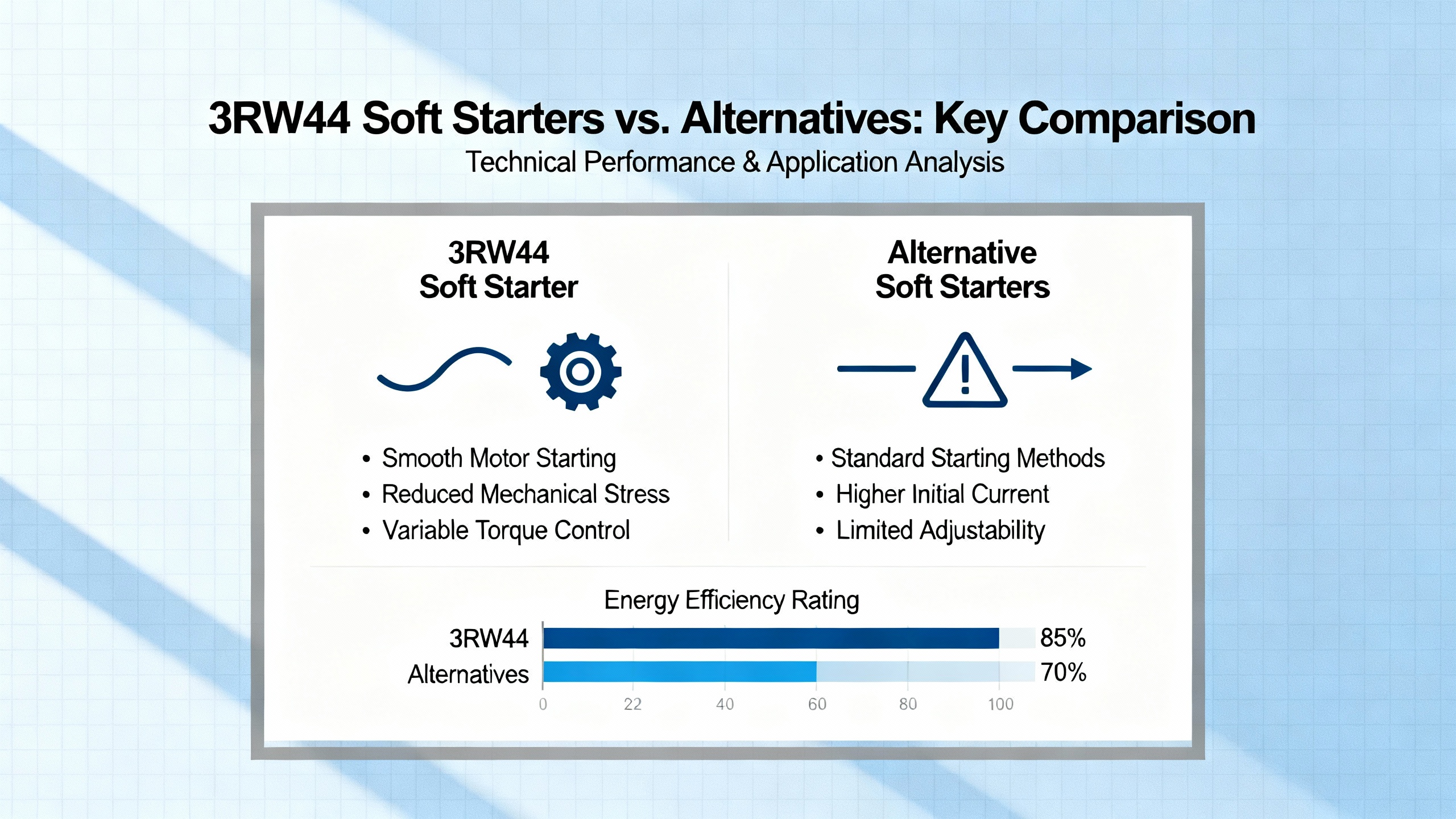
3RW44 Soft Starters Versus Alternatives
When you are in the design phase, you are not just choosing a device; you are choosing a strategy. Siemens themselves publish guidance comparing electronic soft starters such as the 3RW series with autotransformer starters and VFDs, and that guidance matches what many integrators see in the field.
The soft‑starter versus DOL comparison is straightforward. DOL starts are acceptable for small motors, robust mechanical systems, and strong supply networks, but they impose the full six to eight times starting current and high torque shock. The 3RW44, with its controlled current and torque, reduces both electrical and mechanical stress, but adds complexity and electronics that must be protected from harsh environments and poor control power.
Against autotransformer starters, electronic soft starters such as the 3RW44 offer finer control. Autotransformer starters apply one or more fixed reduced‑voltage steps, for example 65 percent of line voltage, which can bring line current down to roughly forty percent of the DOL value and reduce starting torque to about forty to forty‑five percent. However, the transitions between these steps and the final full‑voltage connection still produce mechanical and electrical transients.
The 3RW44, by contrast, lets you shape the ramp and current limit continuously and adds soft stop, integrated protection, and communication diagnostics. It does introduce semiconductor switching and some harmonic content during ramp, but during steady‑state operation the bypass contactor carries the load, keeping losses low.
Compared with VFDs, the 3RW44 is simpler and generally more cost‑effective when you only need smooth starting and stopping. A VFD provides full speed control and high torque at low speed, which is essential in some processes, but it introduces continuous harmonics, often requires filters, and can be more complex to integrate and maintain. For constant‑speed pumps and fans where the process does not require variable speed, a 3RW44 is often the more pragmatic choice.
A compact comparison of the three approaches helps clarify the tradeoffs.
| Aspect | 3RW44 Soft Starter | Autotransformer Starter | Variable‑Frequency Drive |
|---|---|---|---|
| Starting current | Typically about 2–4× motor rated current | Fixed step reduction, about 2.5–3.5× rated | Can be near 1–1.5× rated |
| Mechanical stress | Smooth ramp, low shock | Step changes, moderate shock | Very smooth, best control |
| Speed control | None (fixed frequency) | None | Full speed control |
| Harmonics during operation | Only during ramp | Negligible | Continuous harmonics |
| Protection and diagnostics | Integrated, advanced | Limited, external relays often required | Integrated, advanced |
| Complexity and cost | Moderate | Low to moderate, bulky hardware | Highest, most complex |
FAQ
How much can a 3RW44 soft starter reduce starting current?
Based on Siemens soft‑starter guidance and standard induction‑motor practice, a direct‑on‑line start typically draws roughly six to eight times the motor’s rated current. With a 3RW44 configured as a current‑limit starter, you can usually bring that down to around two to four times rated current, assuming the supply is reasonably stiff and the mechanical load is not extreme. The exact reduction depends on your current‑limit setting, ramp time, and how much torque the driven load needs to accelerate.
Can I use a 3RW44 soft starter on a generator‑fed system?
Yes, 3RW44 soft starters are used on generator supplies, but you must treat generator characteristics as design inputs, not assumptions. The shrimp‑farm example with a 230 kilowatt motor, a 750 kilovolt‑ampere generator, and a 3RW44 soft starter shows that even when the generator appears large on paper, poor voltage regulation or control‑supply design can cause starting failures. Always involve generator specialists, verify that voltage dips and overshoots stay within the soft‑starter tolerance, and test actual start behavior under realistic conditions.
Is the 3RW44 enough motor protection, or do I still need external relays?
The 3RW44 includes extensive motor protection functions, including electronic overload protection, phase‑failure detection, stall and locked‑rotor protection, and underload monitoring. In many standard applications, this is sufficient when properly configured and coordinated with upstream short‑circuit protection. In critical or unusual duty cycles—frequent starts, very long cables, high fault levels—many engineers still add dedicated protection relays for short‑circuit, ground‑fault, or special thermal requirements. The deciding factor is not whether the 3RW44 has protection; it is whether the overall protection concept meets your risk and compliance requirements.
When should I choose a VFD instead of a 3RW44?
If your process requires continuous speed control, energy optimization through variable speed, or very high torque at low speed, a VFD is the appropriate solution. The 3RW44 excels at improving the start and stop of fixed‑speed motors while keeping steady‑state operation efficient and simple. Once you need to modulate speed as part of the process, the 3RW44 is no longer the right tool, and a drive becomes the primary motor‑control device.
Bringing a large motor online is one of the moments when your design either shows its strength or exposes its weak points. The Siemens 3RW44 soft starter is a powerful tool in that moment, but only if you respect what its datasheet is telling you about currents, voltages, protection, and control power. In my experience, projects that treat those numbers as design constraints rather than afterthoughts are the ones that start smoothly on day one and keep running that way for years.
References
- https://www.nrc.gov/docs/ML2109/ML21091A019.pdf
- https://cms.tacoma.gov/Purchasing/FormalBids/TW22-0112F.pdf
- https://www.researchgate.net/figure/The-hardware-used-by-Siemens-soft-starter-3RW44-Series-a-corresponding-schematic_fig7_334131976
- https://studylib.net/doc/18371032/motor-starters--soft-starters-and-load-feeders
- https://www.standardelectricsupply.com/Siemens-3RW4444-6BC34-SIRIUS-Soft-Starter?srsltid=AfmBOootpfyxjzk4lY8ujlIoJcHbUcFvbLSEeCRzPZUjQpXGZluOrGNE
- https://www.farnell.com/datasheets/1685504.pdf
- https://my.goagilix.com/products/sie3rw4444-6bc35
- https://www.sogears.com/blog/siemens-soft-starter-models
- https://www.eng-tips.com/threads/siemens-sirius-soft-starter-3rw44-failure.278084/
- https://cr4.globalspec.com/thread/58062/Generator-Amps-Needed-Siemens-Soft-Starter-Sirius-3RW44-to-Start-230-kw-Motor
Keep your system in play!
Top Media Coverage
Categories


Related articles Browse All
-
 amikong NewsSchneider Electric HMIGTO5310: A Powerful Touchscreen Panel for Industrial Automation2025-08-11 16:24:25Overview of the Schneider Electric HMIGTO5310 The Schneider Electric HMIGTO5310 is a high-performance Magelis GTO touchscreen panel designed for industrial automation and infrastructure applications. With a 10.4" TFT LCD display and 640 x 480 VGA resolution, this HMI delivers crisp, clear visu...
 -
 BlogImplementing Vision Systems for Industrial Robots: Enhancing Precision and Automation2025-08-12 11:26:54Industrial robots gain powerful new abilities through vision systems. These systems give robots the sense of sight, so they can understand and react to what is around them. So, robots can perform complex tasks with greater accuracy and flexibility. Automation in manufacturing reaches a new level of ...
 -
 BlogOptimizing PM Schedules Data-Driven Approaches to Preventative Maintenance2025-08-21 18:08:33Moving away from fixed maintenance schedules is a significant operational shift. Companies now use data to guide their maintenance efforts. This change leads to greater efficiency and equipment reliability. The goal is to perform the right task at the right time, based on real information, not just ...


- Q&A
- Policies How to order Part status information Shipping Method Return Policy Warranty Policy Payment Terms
- Asset Recovery
- We Buy Your Equipment. Industry Cases Amikong News Technical Resources Why choose us
- ADDRESS
-
 32D UNITS,GUOMAO BUILDING,NO 388 HUBIN SOUTH ROAD,SIMING DISTRICT,XIAMEN
Leave Your Comment