
-
Please try to be as accurate as possible with your search.
-
We can quote you on 1000s of specialist parts, even if they are not listed on our website.
-
We can't find any results for “”.
Specifying PWM Output Modules For Reliable Motor Speed Control
Why The PWM Module Matters More Than The Motor Datasheet
When a project team asks me why their new line is full of motors that “don’t respond the way the datasheet promised,” nine times out of ten the root cause is not the motor. It is the PWM output module and how it was specified.
Modern speed control is almost always pulse width modulation. A Control.com technical article describes the core idea clearly: instead of lowering supply voltage, you switch the motor’s rated voltage on and off rapidly and vary the on-time percentage. A 12 V drive at 50% duty behaves like roughly 6 V on average, but the motor still sees full 12 V during each pulse. That lets you keep torque and avoid wasting power in rheostats or series resistors that simply burn energy as heat.
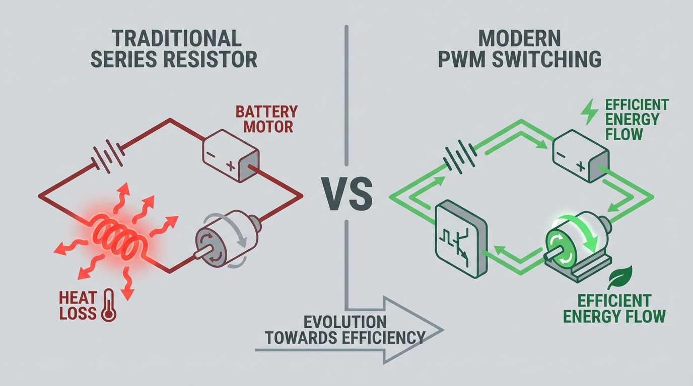
Whether the PWM waveform comes from a PLC card, a dedicated PWM module, or a microcontroller with an enhanced PWM peripheral, the details of that waveform determine how smooth the motor runs, how hot the drive gets, and how long the system survives in production. As Texas Instruments training material on enhanced PWM (ePWM) points out, modern PWM peripherals are sophisticated timing engines with complementary outputs, dead-band insertion, and synchronization. If you under-specify this block, everything downstream has to work harder.
In this article I will walk through how I specify PWM output modules for motor speed control as a systems integrator. The goal is not to sell a particular brand, but to explain which parameters actually matter, what ranges are realistic based on published data, and where you need to be conservative if you want a system that is still running five years from now.
Refresher: What A Motor Really Sees From PWM
Duty Cycle As “Effective Voltage”
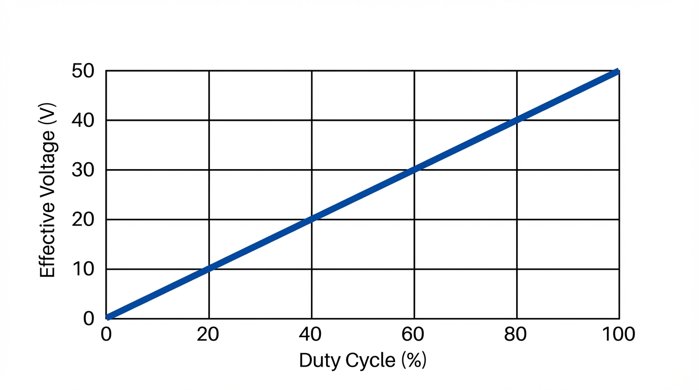
Pulse width modulation starts with two parameters: duty cycle and frequency. The duty cycle is the fraction of each PWM period during which the signal is high. A stepper motor article on EE Power gives a textbook example: if the signal is on for 2 seconds and off for 8 seconds in a 10 second period, the duty cycle is 20%. In that window the device is inactive 80% of the time, so the average power is low.
For DC motors, the arithmetic is the same, just much faster. Several sources, including Control.com and an educational article hosted by AI Future School, highlight the relationship: the average voltage equals duty cycle multiplied by the supply voltage. At 60% duty on a 12 V bus, the motor effectively sees about 7.2 V. WPILib documentation for educational robots explains it the same way using a 12 V motor: a 50% duty PWM drive feels like roughly 6 V.
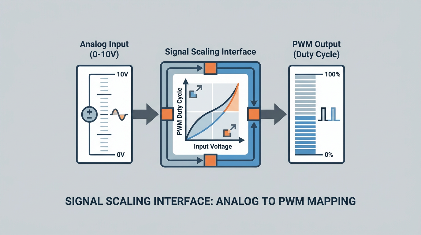
From a control standpoint this means the PWM output module is your digital-to-analog converter. Whether you command it with an analog 0–10 V input, a 4–20 mA loop, or a high-level numeric value from a controller, all of those inputs end up as a duty cycle between 0% and 100%. In practical systems I want that mapping to be monotonic, repeatable, and, where possible, linear over the operating range.
Carrier Frequency And Motor Response
Frequency is how many PWM cycles you produce per second. It drives behavior in two different domains: mechanical response and electrical stress.
Control.com notes that slow loads such as heaters and some motors will tolerate PWM frequencies in the tens to hundreds of hertz, while LEDs and other solid-state loads often need frequencies in the tens of kilohertz to keep flicker and mechanical chatter away. Tektronix’s application note on PWM motor drives shows that industrial variable frequency drives often use carrier frequencies roughly from 2 kHz to 10 kHz, with some newer drives pushing above about 18 kHz to move noise out of the audible range.
Guides for robotics and hobby DC motors, such as material from ThinkRobotics and Same Sky Devices, place typical DC motor PWM frequencies in the neighborhood of about 1 kHz to 20 kHz. Electronics forum discussions and power electronics texts add the key trade-off: higher frequency improves current regulation, reduces torque ripple, and shrinks any passive filters, but it raises switching losses and device heating. For high power or higher voltage, power devices tend to be limited to lower switching frequencies to keep losses under control.
There is no single “correct” frequency. A reasonable process, echoed in engineering Q&A discussions on PWM frequency selection, is to start from application constraints such as audible noise targets, desired current ripple (a common starting point is keeping winding current ripple under roughly 10% of nominal current), and device ratings, then narrow to a candidate band and validate by test.
Motor Inertia And The “Too Slow” Problem
Control.com’s DC motor article stresses another practical point: the motor’s mechanical inertia acts as a low-pass filter. At the PWM timescale the rotor keeps spinning through the off-time of each pulse, so the torque feels like the average over several cycles rather than a series of hard starts and stops. This is exactly why a 256 Hz PWM frequency in the classic 555-based DC motor controller described by Electronics-Tutorials can still yield smooth motion. With the selected RC values, that circuit varies duty cycle from about 8.3% to about 91.7% at a roughly constant 256 Hz, and the motor still runs without obvious stepping.
Drop the frequency too far, though, and you will see problems. The same Control.com article warns that if frequency is too low, DC motors will begin to surge as the mechanical system starts to follow individual pulses rather than the average. In the field I treat “motor appears to breathe or jerk at steady command” as a strong hint that the PWM carrier is lower than it should be or that the power stage and mechanical load do not have enough inertia or inductance to smooth it.
Core Specification Parameters For A PWM Output Module
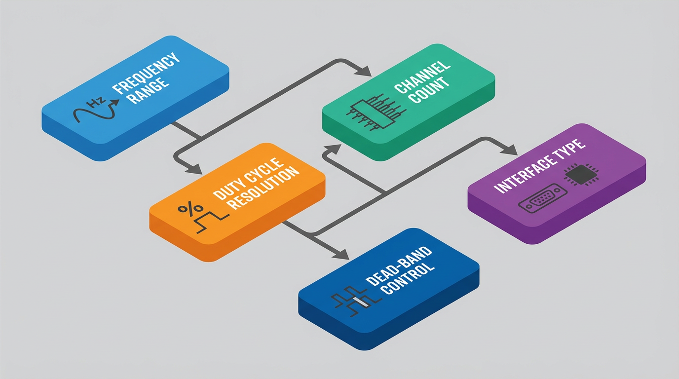
When I sit down with a datasheet for a PWM output card or module, I care less about marketing terms and more about a handful of hard parameters. These parameters show up directly in the tutorials and application notes from Control.com, Maple Systems, Texas Instruments, Microchip-related teaching material, and others.
Here is a compact view of the essentials.
| Parameter | What It Means For Motor Control | Examples And Practical Expectations |
|---|---|---|
| Output signal voltage level | Logic-level voltage and type produced by the PWM module, typically used to drive a solid-state relay or gate driver | Articles on PLC PWM note typical ranges around 3.3–12 V logic that drive transistors or solid-state relays, not the motor |
| Maximum frequency range | Configurable PWM carrier frequency band | Tutorials cite motor PWM use from a few hundred hertz to about 20 kHz for DC motors and 2–10 kHz carriers for industrial VFDs |
| Duty cycle range and resolution | Minimum and maximum duty cycle and how finely it can be stepped | Educational material shows 0–100% duty with 8-bit steps (0–255) on Arduino-style outputs and about 4096 steps in some FPGA PWM implementations |
| Channel count and grouping | How many independent PWM outputs exist and whether they share timing resources | A Maple Systems PWM module example has 12 channels in three frequency groups; a TM4C microcontroller exposes up to 16 PWM outputs through two modules |
| Alignment and mode | Whether pulses are left-aligned, right-aligned, or center-aligned | University lab notes on TM4C devices recommend center-aligned symmetric PWM for AC and brushless drives and left-aligned for general purpose loads |
| Complementary outputs and dead-band | Ability to generate high/low gate signals with adjustable non-overlap for half-bridges | Texas Instruments ePWM and Tiva PWM modules provide hardware dead-band so half-bridge legs avoid shoot-through conduction |
| Output type (relay vs solid-state) | Whether the card uses mechanical relays or solid-state devices | Control.com explicitly warns that PLC relay outputs lack the speed and lifetime to support PWM and should not be used |
| Command interface | How you tell the module what duty cycle and frequency to produce | Sources describe modules accepting 0–10 V or 4–20 mA analog inputs, fieldbus registers, or numeric codes mapped to 0–100% duty |
| Protection behaviors | Built-in handling of out-of-range or disabled commands | WPILib’s PWM interface, for example, reserves a raw value that forces the output low to disable the signal for safety |
Different implementations emphasize different rows. A motion-control microcontroller such as TI’s MSP432E4 will focus on resolution, synchronization, and dead-band. A stand-alone PLC PWM module such as the Maple Systems IO-SD0032PPWM focuses on channel count, frequency grouping, and easy ladder integration. My job is to match those capabilities to what the motor and power stage actually need.
Choosing PWM Frequency For Motor Speed Control
The Fundamental Trade-Off
Several references converge on the same story for frequency selection. Power electronics discussions summarized in engineering forums and a Monolithic Power Systems tutorial on PWM techniques describe PWM frequency as a trade-off among efficiency, component size, and control performance. Higher frequency shrinks inductors and capacitors and improves dynamic response, but switching losses climb roughly in proportion to frequency, especially at higher voltages and powers.
In motor drives you have an extra factor: the motor windings themselves act as inductors. That means you usually do not have to push frequency as high as a small DC-DC converter to get acceptable current ripple. An engineering Q&A captured in the materials notes that a reasonable starting point is to design for winding current ripple under about 10% of nominal current. You select a PWM frequency, check ripple against that target with the known inductance, and adjust.
At the same time, system-level considerations like audible noise and EMI matter. A summary of common practice for “optimal PWM frequency” points out that many motor applications pick frequencies just above the upper audible limit, often in the ballpark of 16–25 kHz for smaller motors, to avoid whining. Large industrial drives often settle lower, around 4–20 kHz, to keep device losses manageable while still mitigating noise.
Application-Class Examples
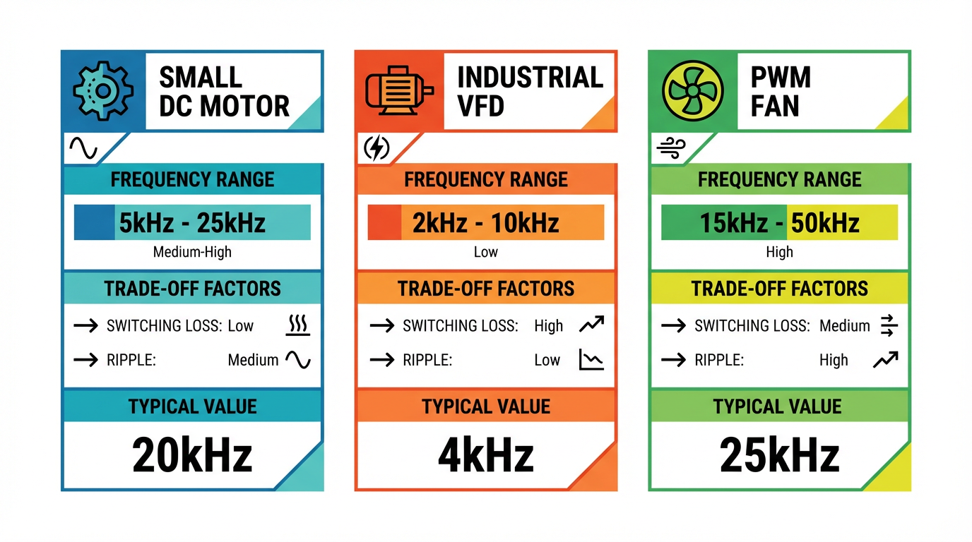
In small DC motor control with PLC hardware, Maple Systems’ tutorial walks through a configuration that uses a fixed 500 Hz PWM frequency for a 12–24 V DC motor. Duty cycle is adjusted through several stages to ramp the speed up and down, but the frequency is fixed across all channels in a frequency group. For moderate power DC motors in industrial panels, a few hundred hertz to a few kilohertz is often acceptable when the mechanical system is geared and coupled through significant inertia.
PWM-controlled fans and blowers are often treated differently. Same Sky Devices notes that most fan applications use PWM around 20–25 kHz and allow 0–100% duty cycle. The higher frequency keeps acoustic noise down, and fan datasheets explicitly call out recommended drive frequencies to guarantee lifetime and avoid resonances.
For AC induction motors on VFDs, Tektronix’s application note on power analysis of PWM motor drives shows typical carrier frequencies in the 2–10 kHz range, with some modern units operating above about 18 kHz. In those systems the controller must vary both the fundamental output frequency (to set motor speed) and the PWM carrier frequency, but the user rarely sees the raw PWM; you just set desired speed and perhaps a “carrier frequency” parameter.
Across all of these, the consistent engineering advice is that there is no universal optimal frequency.
You pick a candidate band based on device capability, mechanical requirements, and acceptable losses, then measure temperature, noise, and control response on the actual machine before you sign off.
Duty Cycle Range, Resolution, And Command Interface
Why Resolution Matters
Once frequency is in the right ballpark, the next question is how finely you can adjust duty cycle. Low-cost microcontrollers exposed through Arduino-style boards typically offer 8-bit resolution, mapping numerical values from 0 to 255 into 0–100% duty cycle. The ThinkRobotics motor control tutorial uses this range directly: analogWrite with a value of 0 produces 0% duty, 255 produces full duty, and values in between act as proportional speed commands.
Educational documentation for the roboRIO FPGA used in WPILib-controlled robots describes finer resolution. That PWM module supports a period of 5, 10, or 20 ms and 4096 discrete pulse-width steps at 1 microsecond resolution. That gives nearly 12 bits of effective resolution over the period for actuators that interpret pulse width directly, such as RC-style motor controllers and servos.
University lab material for the TM4C microcontroller family explains how their PWM modules use 16-bit timers and comparators to generate waveforms. Each generator block has its own counter and compare registers, so you can set periods and duty cycles with fine granularity while the hardware takes care of toggling outputs at the right counts.
For most industrial motor speed applications, anything at or above roughly 8–10 bits of resolution (about 256 to 1024 steps) is usually smooth enough. That rule of thumb appears in engineering notes on PWM frequency selection, where resolution is estimated based on the timer clock and desired frequency. As resolution drops, you start to see noticeable speed jumps when you change commands by a single step, especially at low speeds. When I evaluate a PWM output module specification, I look both at the nominal bit width and at what resolution is left at the chosen frequency, since some modules trade resolution for speed.
Scaling And Interfaces
Different devices expose the PWM command interface differently. Control.com describes PWM controllers that accept an analog 0–10 V or 4–20 mA signal and internally scale that to a duty cycle between 0% and 100%. Maple Systems’ example shows a PLC writing desired duty cycle, ramp time, and frequency into specific module buffer memories using MOV and TO instructions. WPILib, as another example, lets the user write a normalized value between about -1.0 and 1.0 while the library maps that into appropriate pulse widths for whichever controller model is attached.
The lesson for specification is simple. Make sure the PWM module accepts the type of signal your control system can generate easily, and confirm how scaling works. If the control loop outputs “0.0 to 1.0” but the module expects integer duty counts or percentages, you need clear documentation on how that mapping is implemented. Otherwise, what looks like a small percentage tweak in the controller might correspond to a much larger change in motor torque.
Hardware Topology And Protection: Avoiding The Classic Mistakes
The PWM Module Does Not Drive The Motor
One of the more expensive mistakes I have seen on shop floors is wiring a motor directly to a PLC or small PWM module. Maple Systems’ documentation is explicit: the IO-SD0032PPWM terminal block cannot drive the DC motor directly. Instead, the PWM output goes into a dedicated DC motor drive module, which actually switches the motor supply. Control.com makes a similar point when it describes using PWM outputs to drive solid-state relays that in turn switch motor power.
The Arrow Electronics application note on DC motor speed control with PWM reinforces this architecture. Their Raspberry Pi Pico example uses the Pico’s PWM output to drive the gate of an N-channel MOSFET. The motor connects between supply and MOSFET drain, with the source at ground. A 100 ohm resistor on the gate and a 10 kilohm pull-down keep the gate well behaved, and the motor has a flyback diode across it to absorb inductive energy when the MOSFET switches off.
In other words, the PWM output module is a signal-level device.
The motor current flows in a separate circuit through a driver stage designed to handle inductive loads, surge currents, and proper isolation. Any specification that implies the PWM channel can take motor current directly is a red flag.
Flyback Paths, EMI, And Switching Losses
Inductive loads fight changes in current. When you abruptly turn off current through a motor, you get a voltage spike that can easily exceed the transistor’s rating unless you give that current somewhere safe to go. The Electronics-Tutorials motor-speed article makes this explicit in its 555-based PWM design. A flyback diode placed across the motor is required to protect the transistor from the inductive voltage spike.
Same Sky Devices’ overview of PWM disadvantages adds more items to the risk list: switching spikes, electromagnetic interference, harmonic distortion, and electrical noise. Tektronix’s PWM drive application note shows that harmonic and carrier-frequency currents can cause extra heating and negative-sequence magnetic fields that reduce usable torque. These are not theoretical academic concerns. I have personally seen a small microcontroller board rendered unusable when a motor driver shield was powered at 12 V without adequate decoupling capacitors, a failure that matches the cautionary story in Arrow’s application note about an L293D driver damaging a Raspberry Pi Pico.
When I specify a PWM output module, I therefore check that the documentation covers compatible driver topologies and protection components. Even if the module itself is only providing logic-level pulses, its datasheet should mention things like maximum output slew rate, recommended cabling practices, and isolation. Then, in the power stage design, I insist on proper flyback paths, decoupling, and thermal management.
Relay Outputs Are Not PWM Outputs
The Control.com article on PWM in PLCs makes a blunt but necessary statement: relay outputs do not have the speed or mechanical life to support PWM. If a PLC vendor says an output can be configured as PWM but the hardware is a mechanical relay, treat that feature as a configuration artifact, not a real option. For sustained speed control you want transistor or solid-state outputs, or a dedicated PWM module designed to switch at kilohertz rates indefinitely.
Matching PWM Output Specs To Motor Type
Simple DC Motors In Automation
For conveyors, indexing drives, and small actuators using brushed DC motors, the Maple Systems example is a good representation of how to do it right with a PWM module. Their design uses a separate DC motor drive module powered from a dedicated 24 V supply. The PLC’s PWM module provides the speed reference as a duty cycle at a constant 500 Hz. Ladder logic sets up stages with different target duty cycles, and each stage ramps over about 5 seconds, giving the motor time to accelerate or decelerate smoothly over a 10 second window before the next change.
This approach highlights a few specification points. Frequency is fixed within a frequency group on the module, so you need to ensure that fixed value is acceptable for all motors on that group. The DC motor drive module has its own current limits and protections, so you must match its ratings to the motor rather than relying on the PWM card. And the PLC must have enough resolution in its command registers to adjust duty cycle in reasonably fine increments.
Brushless And Stepper Motors
Stepper motor control literature from EE Power compares simple PWM current control to more advanced sinusoidal control. PWM is used to regulate current in the motor windings by varying pulse width, while sinusoidal control shapes the current more closely to a sine wave, improving smoothness and efficiency at higher speeds. In many modern drives, a microcontroller or dedicated controller chip generates PWM based on feedback, and the power stage amplifies that into the motor.
University lab notes on PWM in embedded systems describe symmetric center-aligned PWM as a preferred choice for three-phase AC induction and brushless DC motors because it reduces current harmonics and maintains better phase alignment. Asymmetric left-aligned PWM is more common for general-purpose loads and certain stepper arrangements. If your application involves BLDC or stepper motors, it is worth specifying PWM hardware that supports the alignment mode and synchronization features your drive algorithms require, or simply using an integrated drive that hides those details.
Three-Phase AC Motors On VFDs
For large fans, pumps, and process drives, most plants use fully integrated PWM variable frequency drives rather than raw PWM output modules. Tektronix’s application note clarifies what those drives are doing internally. They rectify three-phase AC to a DC bus, then use an inverter with three switch pairs to generate three-phase PWM outputs whose average line-to-line voltages are nearly sinusoidal. The control electronics generate three low-frequency sinusoidal references, 120 degrees apart, that modulate carrier pulses at a few kilohertz.
Although you typically do not see the raw PWM when specifying a VFD, the same concerns apply. Carrier frequency affects motor heating and audible noise. Harmonic performance affects torque and efficiency. When I tie a PLC into a VFD, the PWM is inside the VFD, but I still care that the VFD’s internal PWM hardware is robust, and that the control interface between PLC and VFD accurately represents the desired speed or torque.
Verifying A PWM Output Module In The Field
However clean the datasheet looks, I never consider a PWM specification complete until it is validated on real hardware. Measurement guidance from Tektronix and practical examples from Maple Systems and Arrow illustrate the process.
On first power-up, I connect an oscilloscope or a combined power analyzer and scope to the PWM output at the driver input. With the motor disconnected or lightly loaded, I command a series of duty cycles and verify that the pulses correspond to the expected on-time at the chosen frequency. If the module claims 0–100% duty, I check whether it really reaches both extremes or if there is a built-in dead band at the ends.
Next I add the motor and its driver, watching the gate or control node as well as motor current. The goal is to confirm that the driver is interpreting the PWM correctly and that current waveforms are reasonable, without extreme spikes or oscillations. Tektronix’s PWM measurement mode, for example, separates total RMS and fundamental components to show how much harmonic current is present. Even with simpler tools, you can see whether torque ripple and audible noise match expectations.
Finally, I exercise acceleration and deceleration sequences. Maple Systems’ example uses 5 second ramps between different duty setpoints. In my own projects I often start with a similar ramp profile and adjust based on mechanical response. The PWM module has to react with deterministic timing; if duty updates are jittery or quantized too coarsely, the motor will tell you.
Putting It Together: A Practical Specification Mindset
When you view a PWM output module through the lens of real motor performance, the specification starts to look less like a checkbox list and more like a risk management exercise.
You need confidence that the module can generate the right waveform, at the right frequency and resolution, synchronized across channels when necessary. You need a clear strategy for how that waveform reaches the motor, whether via a dedicated DC motor drive module, an H-bridge driver, or a full VFD. You need to understand the trade-offs inherent in your chosen PWM frequency and how they will show up as heat, noise, or torque ripple. And you need to know how to measure these things in the field, using scopes and power analyzers that are capable of dealing with PWM waveforms rather than being fooled by their harmonics.
The good news is that the building blocks are well understood. Application notes from Control.com, Maple Systems, Texas Instruments, Monolithic Power Systems, Tektronix, Same Sky Devices, and others describe both the underlying theory and the practical pitfalls. In my experience, teams get into trouble not because PWM is exotic, but because small gaps in the PWM module specification multiply as the project moves from drawing to panel to plant floor.
If you treat the PWM output module as a first-class component in your motor control design, verify its behavior early with real measurements, and respect the interaction between duty cycle, frequency, and the power stage, you end up with a drive system that behaves predictably. That is what you want as a project partner: motors that start, stop, and track setpoints the same way on Monday morning as they did during the factory acceptance test.
References
- https://docs.wpilib.org/en/stable/docs/software/hardware-apis/motors/pwm-controllers.html
- https://www.researchgate.net/publication/224600301_Comparison_between_different_PWM_control_methods_for_different_Z-source_inverter_topologies
- https://www.airsupplylab.com/ti-tiva-series/tiva_lesson-13-pulse-width-modulation-pwm.html
- https://www.electronics-tutorials.ws/blog/pulse-width-modulation.html
- https://gagner-toomey.com/master-pwm-controllers-setup-optimization-and-key-comparisons/
- https://www.sameskydevices.com/blog/pulse-width-modulation-pwm-how-it-works-and-why-its-essential-in-electronics?srsltid=AfmBOoo7-Fwt3_rYxv44qYu3JQ2X-PSVeLT8Ly8g24YmhHvjcpSZ2be2
- https://www.wevolver.com/article/what-is-a-pwm-signal-fundamentals-and-practical-applications-for-engineers
- https://labs.dese.iisc.ac.in/embeddedlab/pwm/
- https://www.ai-futureschool.com/en/electronics/how-pwm-modulators-control-motor-speed.php
- https://forum.allaboutcircuits.com/threads/how-to-choose-the-optimal-pwm-frequency.193649/
Keep your system in play!
Top Media Coverage
Categories


Related articles Browse All
-
 amikong NewsSchneider Electric HMIGTO5310: A Powerful Touchscreen Panel for Industrial Automation2025-08-11 16:24:25Overview of the Schneider Electric HMIGTO5310 The Schneider Electric HMIGTO5310 is a high-performance Magelis GTO touchscreen panel designed for industrial automation and infrastructure applications. With a 10.4" TFT LCD display and 640 x 480 VGA resolution, this HMI delivers crisp, clear visu...
 -
 BlogImplementing Vision Systems for Industrial Robots: Enhancing Precision and Automation2025-08-12 11:26:54Industrial robots gain powerful new abilities through vision systems. These systems give robots the sense of sight, so they can understand and react to what is around them. So, robots can perform complex tasks with greater accuracy and flexibility. Automation in manufacturing reaches a new level of ...
 -
 BlogOptimizing PM Schedules Data-Driven Approaches to Preventative Maintenance2025-08-21 18:08:33Moving away from fixed maintenance schedules is a significant operational shift. Companies now use data to guide their maintenance efforts. This change leads to greater efficiency and equipment reliability. The goal is to perform the right task at the right time, based on real information, not just ...


- Q&A
- Policies How to order Part status information Shipping Method Return Policy Warranty Policy Payment Terms
- Asset Recovery
- We Buy Your Equipment. Industry Cases Amikong News Technical Resources Why choose us
- ADDRESS
-
 32D UNITS,GUOMAO BUILDING,NO 388 HUBIN SOUTH ROAD,SIMING DISTRICT,XIAMEN
Leave Your Comment