
-
Please try to be as accurate as possible with your search.
-
We can quote you on 1000s of specialist parts, even if they are not listed on our website.
-
We can't find any results for “”.
Torque Mode Servo Drives for Force Control Applications
When you stop caring about how far the axis moves and start caring about how hard it pushes, you are in force‑control territory. That is where torque mode on a servo drive stops being an advanced feature and becomes a core requirement.
I have helped commission enough press‑fit stations, tension stands, and torque tools to see the same pattern: projects run smoothly when the team understands what torque mode actually does in the drive and where its risks are. When they do not, you get inconsistent force, mysterious runaway events, and a lot of finger‑pointing between controls and mechanical teams.
This article walks through torque‑mode servo control from a systems integrator’s point of view, grounded in what manufacturers like AutomationDirect, ADVANCED Motion Controls, Festo, and others describe in their technical notes. The focus is very specific: how to use torque mode as a practical foundation for force control, and when you are better off staying in velocity or position mode instead.
From Position To Force: Why Torque Mode Exists
A servo system can precisely control position, speed, and torque. The question is which of those three you treat as the primary command.
In most industrial automation, we command position or speed. Packaging lines, CNC machines, robots, and conveyors care about “move here in this time” or “run at this speed.” The servo’s torque loop works in the background to make those things happen, but nobody commands torque directly.
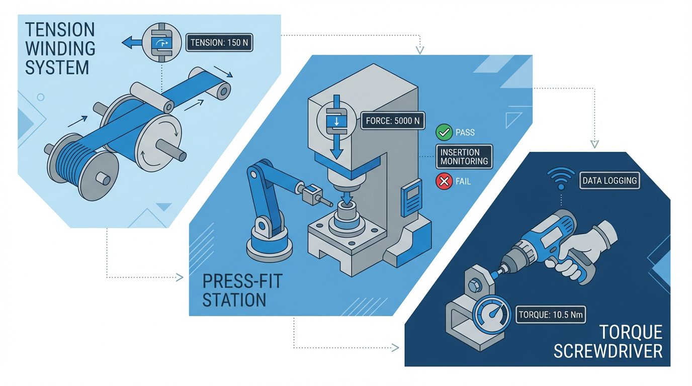
Force control flips that around. In tension control, press‑fit, nut‑running, load testing, and many robotics tasks, the mechanical requirement is “apply this force or torque, and let position or speed float as needed.” MotionControlTips describes classic examples: winding systems that must maintain web tension as roll diameter changes, and injection molding where a constant clamping force is more important than exact clamp position. The same logic applies to capping machines, torque screwdrivers, and press‑fit cells where breaking a part is more expensive than being off a few thousandths of an inch.
Because motor torque is directly proportional to phase current, torque mode in the drive is the natural way to turn the servo into a controlled force source. You command torque; the drive tightly regulates current to match that torque; and the resulting force at the tooling is defined by your mechanics and transmission ratio.
How A Servo Drive Thinks: Cascaded Control Loops
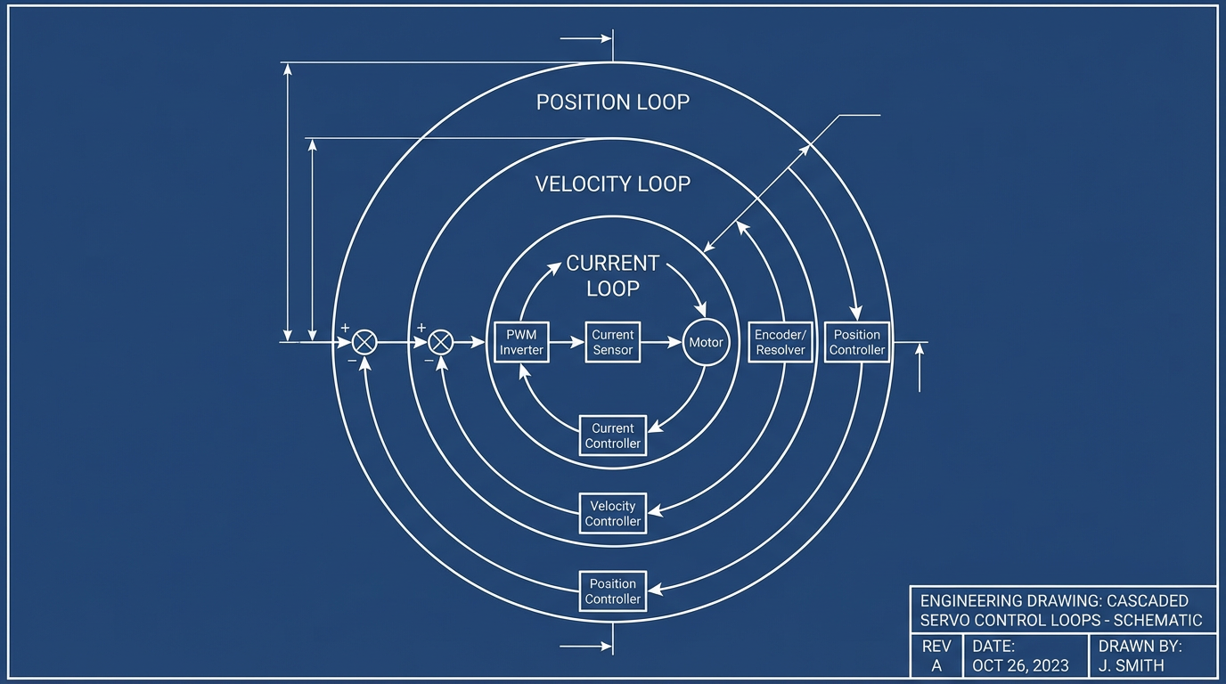
To understand torque mode, you need the control‑loop stack inside the drive.
Technical articles from AutomationDirect and MotionControlTips describe servo control as a set of cascaded feedback loops. The innermost loop regulates current (and therefore torque). Around that sits the velocity loop, and around that sits the position loop when you are doing position control.
In all modes, the current loop is active. MotionControlTips explains that torque mode is effectively “current mode”: the drive measures phase current, infers actual torque, compares it to the commanded torque, and adjusts the output using a proportional–integral controller. This loop is always tuned for fast response because it underpins every other mode.
In velocity mode, the drive adds a speed loop around the current loop. It measures speed via encoder or resolver feedback, compares it to a commanded speed, and determines how much torque (current) is needed to correct the error. The current loop then enforces that torque.
Position mode adds the outermost loop. The controller or drive compares actual position to the commanded position, computes an error, and uses the inner velocity and current loops to drive the axis into place without overshoot or instability.
Festo and AutomationDirect both emphasize that modern servo drives often embed quite a bit of motion logic inside the drive itself: registration functions, electronic camming, flying shear profiles, and even on‑the‑fly switching between speed and torque modes in tension applications.
That flexibility is powerful, but it does not change the basic structure of the cascaded loops.
Torque mode simply exposes the innermost variable directly to your motion controller.
Inside Torque Mode: The Drive As A Torque Amplifier
A useful way to think about torque mode comes from an experienced engineer in a Control.com discussion: in torque mode the drive behaves like a torque amplifier.
Both torque and speed modes often share the same analog command interface. In the example discussed on Control.com, a ±10 V signal from the host controller feeds the drive. In speed mode, that voltage corresponds to a target velocity. In torque mode, the exact same voltage corresponds instead to target torque. A 5 V command is typically about half of the available torque or speed, depending on the mode.
In torque mode, the drive closes only the internal torque loop and handles commutation. It regulates current so the motor produces the requested torque. Everything beyond that is your problem. The external controller must close the velocity and position loops, using encoder feedback and its own algorithms.
That gives the host controller maximum authority. You can implement custom force‑vs‑position curves, adaptive tuning, or application‑specific behaviors that no generic drive firmware will ever ship with. This is why experienced motion engineers prefer torque mode when the host controller can update velocity and position fast enough.
The tradeoff is that the burden moves into your control system.

You now own the higher‑level loops and their stability. If your PLC or motion controller is not designed for tight, fast velocity control, torque mode can actually reduce performance and safety rather than improve it.
Torque, Velocity, And Position Modes Compared
The MotionControlTips explanation of torque and velocity modes, combined with the Control.com account of analog command behavior, leads to a simple comparison that matters for force control work.
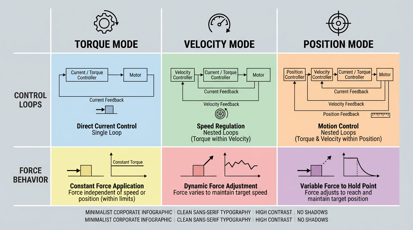
| Mode | Primary variable the drive controls | Which loops are inside the drive | How force behaves | Typical uses mentioned in the literature |
|---|---|---|---|---|
| Torque mode | Torque (current) | Current loop only | Directly commanded; speed and position are side effects | Winding tension, injection molding clamp force, torque tools, load testing, web handling |
| Velocity mode | Speed | Current and velocity loops | Adjusted automatically to hold speed against load variations | Conveyors, fluid or adhesive dispensing, grinding and polishing, many CNC processes |
| Position mode | Position | Current, velocity, and position | Whatever is needed to achieve commanded position and profile | Indexing tables, pick‑and‑place, most general multi‑axis motion |
For force‑critical applications, torque mode is appealing because the relationship between command and torque is explicit.
Velocity and position modes are better when you care about keeping speed or position on target and force is secondary, as in grinding where constant surface speed is key.
Where Torque Mode Shines In Force Control
The published examples of torque‑mode applications line up very well with what works in the field.
MotionControlTips points to winding and injection molding as classic torque‑mode use cases. In winding and web handling, you want constant tension even as roll diameter and inertia change. Torque mode lets you command a torque that maps to a consistent web tension, while position and speed can float as diameter evolves. The torque loop handles rapid disturbance rejection; your controller only needs to adjust the torque command as geometry changes.
In injection molding, the clamp mechanism must deliver a stable clamping force during the hold phase. Here again, absolute clamp position is far less important than force. Torque mode lets the controller maintain that force even if the mold or machine structure flexes slightly.
The Control.com discussion extends the list to nut runners, load testing, and general web‑handling systems. In nut‑running or capping, the control objective is a torque limit: tighten until you hit a defined torque, then stop or switch modes. A drive that accepts a torque command and can clamp torque quickly makes that straightforward. Press‑fit and forming operations follow the same pattern: push to a torque threshold, or enforce a torque‑versus‑displacement profile rather than a hard position.

Articles from ADVANCED Motion Controls and RealPars highlight another angle: servo drives with sophisticated torque control and encoder feedback are excellent for pressing, holding, pushing, and twisting motions where too much torque can crush parts and too little torque leads to slippage or defective assembly. Digital servo drives can expose torque parameters that let you clamp the allowable torque window precisely. In torque mode, that torque command is not a secondary limit; it is the main reference.
CSK and ITG Motor descriptions of high‑torque servo motors reinforce this point from the hardware side. These motors are designed to deliver significantly higher torque than standard servos while maintaining precise closed‑loop control of position, speed, and torque. That combination is exactly what you want when you are running heavy press‑fit or clamping applications continuously and still need sub‑millimeter placement accuracy.
For high‑end machinery, torque motors as described by Heidenhain and Mosrac go further by eliminating gearboxes, belts, and other transmission elements. They couple the load directly to the motor rotor and are sized primarily on torque, not power. That direct‑drive architecture removes backlash and compliance, which gives torque‑mode control a cleaner relationship between commanded torque and actual force at the tool.
Pros And Cons Of Torque Mode For Force Control
Torque mode is not automatically the right answer just because “force control” appears in the requirements. There are real tradeoffs that come up again and again.
On the positive side, torque mode gives the host controller full authority. The Control.com engineer notes that this allows custom motion algorithms, dynamic tuning, and fine‑grained torque limiting that can respond to changing load conditions in real time. MotionControlTips emphasizes that in torque‑mode winding and clamping applications you can shape the torque response exactly to the process, without fighting a drive that is trying to prioritize speed.
Torque mode also makes certain safety and quality strategies easier to implement. RealPars and ADVANCED Motion Controls both describe how servo drives can raise faults when measured position or torque error exceeds a defined limit. When you own the torque command, you can treat those faults as hard interlocks: drop the torque request to zero, open a safety circuit, or engage a secondary brake when anything looks wrong.
On the negative side, torque mode is far less forgiving of mistakes in the upper‑level control system. The Control.com discussion points out a critical safety concern: if the host controller loses position or velocity feedback but continues to send a torque command, the motor can accelerate to full speed and stay there until the command or power is removed. In velocity mode, similar feedback loss will generally just leave the motor running at the last commanded speed, which is still dangerous but usually less explosive.
Torque mode also increases the tuning burden. Your host controller must close the velocity and position loops. If it does so at a slower update rate than the drive could achieve internally, you have traded away dynamic performance and robustness for no real benefit. That is why some older motion controllers and PLC servo cards only supported velocity‑mode drives; their internal velocity loops were not fast enough to justify torque mode.
Finally, torque mode makes force control behavior more sensitive to mechanical design faults. Backlash, compliance, and friction all show up as differences between commanded torque and resulting motion. Direct‑drive torque motors, high‑torque servos with rigid gearboxes, and well‑sized couplings all help, but they also raise hardware cost. ITG Motor, Heidenhain, Mosrac, and Kollmorgen all stress that proper servo and motor sizing, torque margins, and mechanical stiffness are essential for getting the promised accuracy and life out of torque‑centric systems.
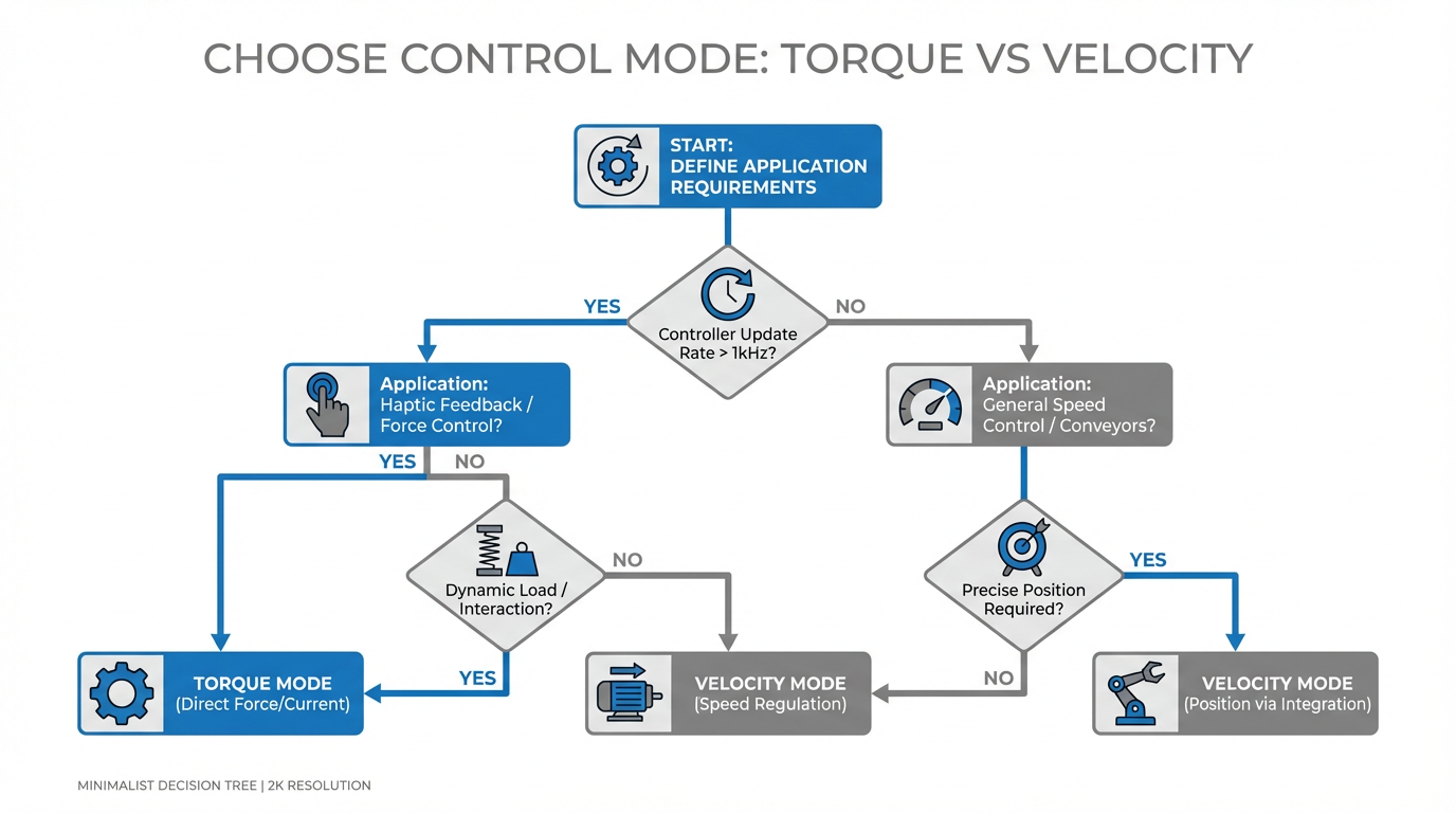
Choosing Between Torque And Velocity Mode For Force‑Sensitive Tasks
The rule of thumb repeated in engineering forums and summarized in the Control.com notes is straightforward: if the drive can close the velocity loop faster than your host controller, you generally prefer velocity mode; if your controller can update faster and you need fine torque behavior, torque mode becomes attractive.
MotionControlTips describes how velocity mode uses a speed loop wrapped around the torque loop. This loop keeps the motor at the commanded speed despite load changes. That is ideal for applications such as grinding or polishing where a constant surface speed is the main objective. Force still changes as the tool engages the work, but the drive automatically increases or decreases torque to hold speed. You can still use torque limits as secondary protection, but they are not the primary command.
In tension control, this turns into a practical choice. AutomationDirect notes that some tensioning applications switch between speed and torque modes on the fly. For example, when spooling a flexible saw blade, you might run in speed mode most of the time, then switch to torque mode during a critical section where tension matters more than surface speed. That hybrid approach leverages the strengths of each mode without overcomplicating the overall design.
For pure force‑driven processes, torque mode is usually worth the extra integration effort. Nut‑running, press‑fit, spring testing, friction characterization, and clamp‑force control all fall into this bucket. If you try to solve those in velocity mode, you end up doing indirect force control by modulating speed commands and torque limits, which is workable but less transparent and harder to reason about when something goes wrong.
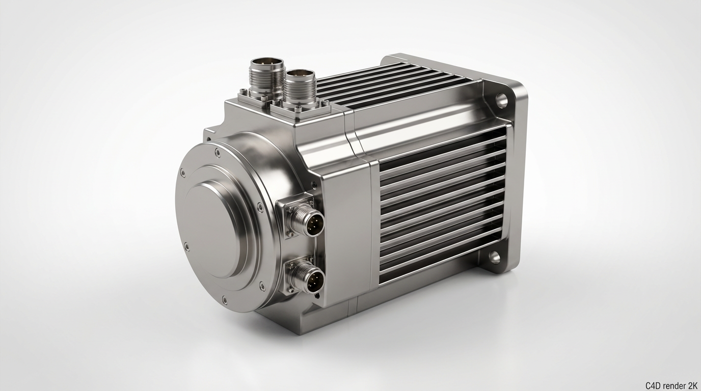
Motor And Drive Selection For Torque‑Mode Force Control
Once you commit to torque mode, the hardware selection has to support it. The research from AutomationDirect, ITG Motor, CSK, Heidenhain, Mosrac, Kollmorgen, and ADVANCED Motion Controls all converge on the same themes.
First, torque capacity dominates. ITG Motor explains that high‑torque servo motors are specifically designed to deliver significantly greater rotational force than standard units while maintaining precise closed‑loop control. That makes them ideal for heavy‑load applications such as large robots, CNC machines, and conveyor systems where the motor must both move and hold substantial loads.
Second, dynamic response matters. IIS Servo and Kollmorgen both highlight motors with high torque‑to‑inertia ratios. A higher torque‑to‑inertia ratio allows the motor to change speed rapidly with good control, which is critical when your torque command changes quickly, as in high‑speed press‑fit or tension applications with abrupt disturbances. Kollmorgen’s guidance stresses the combination of high torque density, low inertia, and low cogging for smooth, responsive motion.
Third, pay attention to the drive’s torque‑mode capabilities. ADVANCED Motion Controls notes that modern digital servo drives can expose torque parameters directly and even store motion indexes and sequences internally. AutomationDirect’s SureServo2 family offers high bandwidth velocity loops, advanced tuning tools, and built‑in features such as registration and electronic camming. For torque‑mode work, high current‑loop bandwidth and good diagnostic tools are more important than sophisticated position profiles. You want a drive that really behaves as a predictable torque amplifier.
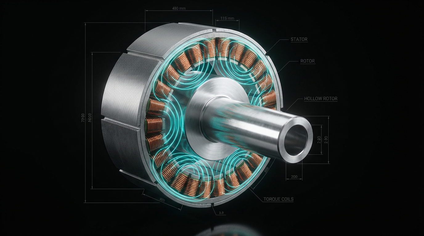
Fourth, consider direct‑drive torque motors where appropriate. Heidenhain describes torque motors as frameless, direct‑drive brushless synchronous motors with a high pole count and a large hollow shaft. They are selected on torque rather than power and are intended to run without gearboxes or belts. Mosrac’s examples show torque motors delivering high torque at modest speeds with minimal mechanical wear and outstanding smoothness. If your mechanical design can accommodate a torque motor, torque‑mode force control becomes cleaner because there is virtually no backlash or compliance between motor and load.
Finally, make encoder and feedback choices with force control in mind. Mosrac highlights high‑resolution magnetic absolute encoders with about 17‑bit resolution and tight accuracy, and AutomationDirect details options for high‑resolution encoders up to 24‑bit. In torque‑mode force control, you still need good position feedback for higher‑level algorithms, detecting slip, and enforcing travel limits even if position is not the primary command.
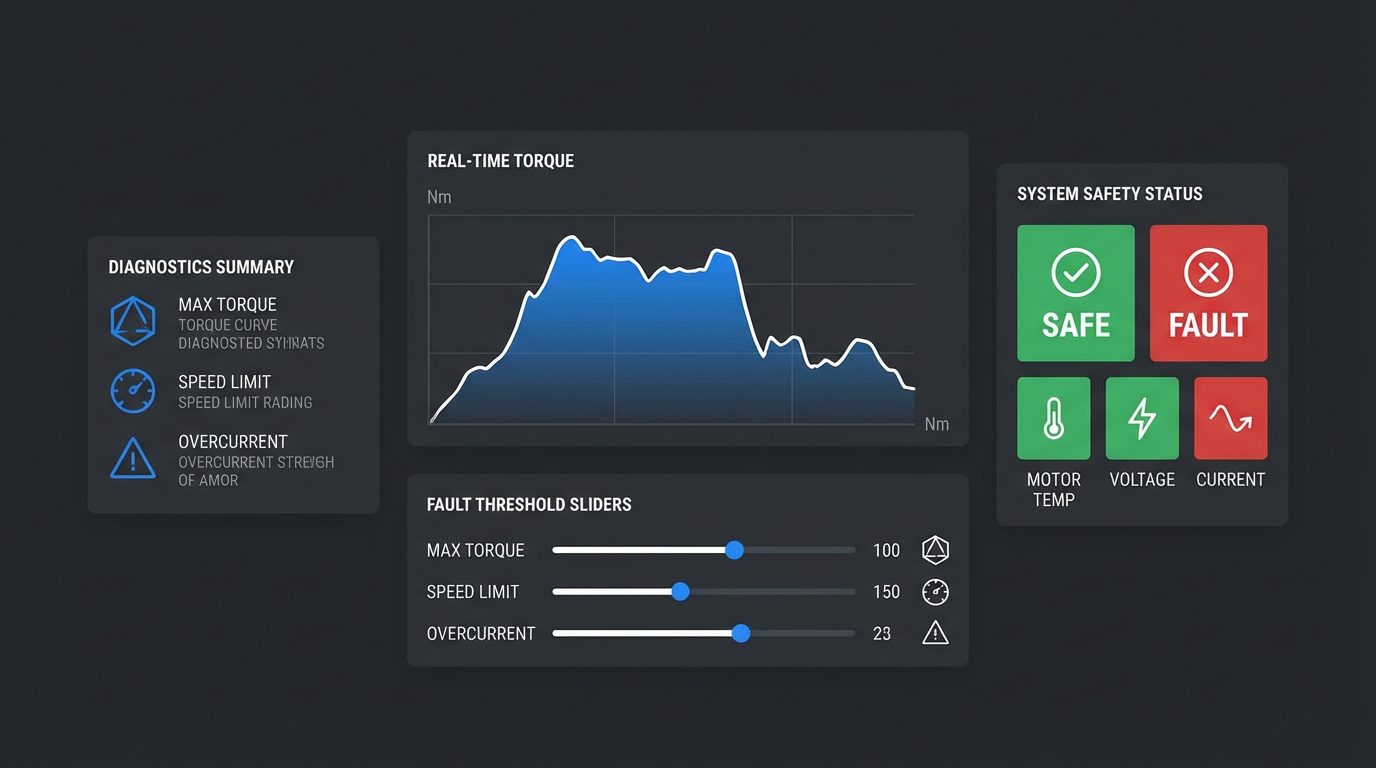
Safety, Tuning, And Diagnostics In Torque Mode
If you adopt torque mode without a safety strategy, you are asking for trouble. The Control.com account of runaway behavior is not theoretical; torque mode will happily accelerate an axis if it sees a nonzero torque command and no opposing load, regardless of whether your position display has gone dark.
Servo manufacturers have built multiple protective features into their products. AutomationDirect’s servo families include Safe Torque Off functions directly in the drive, so you can remove torque quickly during emergency stops without bulky external contactors. RealPars points out that servo drives can monitor position error and fault if the error exceeds a configurable threshold, preventing undetected missteps and uncontrolled motion. ADVANCED Motion Controls emphasizes the diagnostic power of digital drives, which can log status, expose internal variables, and run motion indexes autonomously for troubleshooting.
From a project perspective, the work is to wire and configure these features so they are effective in torque mode. That means using Safe Torque Off channels correctly, validating that position and torque error limits are realistic for your process, and proving that the system goes to a safe state when feedback is lost or a fault occurs. It also means respecting duty‑cycle limits. RealPars reminds us that servo motors can deliver several times rated torque for short intervals, but peak torque is limited to very low duty cycles and sustained overload will damage the motor.
Tuning is another area where torque mode demands more discipline. AutomationDirect describes several tuning options, from fully manual tuning to one‑touch automatic tuning and built‑in oscilloscopes to visualize loop response. RealPars notes that tuning a servo can be time‑consuming and that a poorly tuned servo can become unpredictable. In torque mode you are usually tuning at two levels: the drive’s inner loop (which is often preconfigured by the vendor) and the outer velocity and position loops in your controller. Using vendor auto‑tuning tools as a starting point and then refining gain values based on real‑world test moves tends to give the best outcome.
Diagnostics and connectivity also deserve attention. IIS Servo and RoboticsTomorrow both describe how modern servo drives provide rich real‑time data over industrial networks. That data typically includes torque, position error, temperature, and fault information. In a torque‑mode system, logging torque commands and actual torque, along with resulting motion, allows you to spot creeping friction, mechanical damage, or process drift before they become production‑stopping failures.
A Practical Commissioning Pattern For Torque‑Mode Force Control
In the field, the commissioning pattern that works looks very similar from project to project, even though the mechanics vary.
You begin by getting the motor and drive running in a safer mode, usually velocity or position mode, with conservative speed and torque limits. Using the drive’s auto‑tuning tools and oscilloscopes, you confirm that the basic loops are stable and that the encoder feedback is sound. This step is exactly what AutomationDirect and Festo recommend for general servo commissioning.
Next, you enable torque‑mode capability but start with very low torque commands. MotionControlTips’ description of cascaded loops helps here: even in torque mode, your host control can close a simple velocity loop so the axis does not free‑spin when you apply torque. You verify that commanding a small positive or negative torque produces the expected steady force and that torque readings match your expectations.
Once the basic behavior is confirmed, you bring in the process‑specific logic. If the application is tension control, you map torque commands to measured tension and adjust your gains until the system tracks setpoints without oscillation. In a press‑fit application, you program force‑versus‑position or force‑versus‑time profiles and confirm that the system reacts appropriately to hard stops and part tolerances. The examples from RealPars and ADVANCED Motion Controls about torque limits and fault thresholds are particularly relevant here; you want clear boundaries where the system transitions from control to safe shutdown.
Finally, you exercise edge cases. Simulate broken sensors, unplug feedback, push the axis against unexpected obstacles, and verify that Safe Torque Off, fault limits, and mechanical brakes all behave as designed. This is where torque mode’s risks show up early, in a controlled environment, instead of after production has started.
Short FAQ: Torque Mode And Force Control
Do I need a special drive to use torque mode for force control?
Technical sources such as MotionControlTips explain that many modern servo drives support torque, velocity, and position control modes using the same hardware. What matters is that the drive exposes a torque‑mode interface and has a well‑tuned current loop. Drives from vendors like AutomationDirect, Festo, ADVANCED Motion Controls, and others typically meet this requirement as long as you configure them correctly and provide a suitable host controller to close the outer loops.
Is torque mode always better than velocity mode for force‑sensitive applications?
No. MotionControlTips and the Control.com discussion both stress that the choice depends on what you primarily care about and on where the fastest, most robust velocity loop can run. If constant speed is the main requirement and force can be managed with limits and monitoring, velocity mode is simpler and often safer. Torque mode makes sense when the process genuinely depends on controlling torque itself, such as tension, clamping, or torque tools, and when your controller can support the necessary update rates and safety logic.
Can high‑torque servo motors or torque motors improve my force control?
Sources from ITG Motor, CSK, Heidenhain, and Mosrac show that high‑torque servo motors and direct‑drive torque motors are purpose‑built for delivering large torque with precise control. In force‑control applications that run near the limits of a standard servo or where backlash and compliance are a problem, these motors can significantly improve both control quality and reliability. They do raise hardware cost, so they are best justified in heavy‑duty or high‑precision equipment where uptime and quality matter more than initial price.
Force control work separates motion systems that merely move from those that can interact with the product intelligently. Torque‑mode servo drives, paired with well‑chosen motors and a disciplined control architecture, give you that capability. When you design and commission them carefully, they stop being a science project and become a reliable part of your toolbox for building robust, production‑ready machines.
References
- https://www.geeksforgeeks.org/electrical-engineering/applications-of-servo-motor/
- https://www.plctalk.net/forums/threads/velocity-versus-torque-mode.105967/
- https://www.a-m-c.com/servo-drive-top-benefits-motion-control-applications/
- https://library.automationdirect.com/what-is-industrial-servo-control/
- https://darwinmotion.com/blogs/servo-motor-applications-in-industry
- https://itg-motor.com/high-torque-servo-motors-definition-applications-and-key-benefits/
- https://www.motioncontroltips.com/whats-the-difference-between-torque-mode-and-velocity-mode-in-servo-control/
- https://perspectivasolutions.com/how-the-servo-works-in-industrial-automation/
- https://www.realpars.com/blog/servo-motors-advantages
- https://www.cnczone.com/forums/servo-motors-drives/66964-torque-mode-position-mode-speed-velocity-mode-new-post.html
Keep your system in play!
Top Media Coverage
Categories


Related articles Browse All
-
 amikong NewsSchneider Electric HMIGTO5310: A Powerful Touchscreen Panel for Industrial Automation2025-08-11 16:24:25Overview of the Schneider Electric HMIGTO5310 The Schneider Electric HMIGTO5310 is a high-performance Magelis GTO touchscreen panel designed for industrial automation and infrastructure applications. With a 10.4" TFT LCD display and 640 x 480 VGA resolution, this HMI delivers crisp, clear visu...
 -
 BlogImplementing Vision Systems for Industrial Robots: Enhancing Precision and Automation2025-08-12 11:26:54Industrial robots gain powerful new abilities through vision systems. These systems give robots the sense of sight, so they can understand and react to what is around them. So, robots can perform complex tasks with greater accuracy and flexibility. Automation in manufacturing reaches a new level of ...
 -
 BlogOptimizing PM Schedules Data-Driven Approaches to Preventative Maintenance2025-08-21 18:08:33Moving away from fixed maintenance schedules is a significant operational shift. Companies now use data to guide their maintenance efforts. This change leads to greater efficiency and equipment reliability. The goal is to perform the right task at the right time, based on real information, not just ...


- Q&A
- Policies How to order Part status information Shipping Method Return Policy Warranty Policy Payment Terms
- Asset Recovery
- We Buy Your Equipment. Industry Cases Amikong News Technical Resources Why choose us
- ADDRESS
-
 32D UNITS,GUOMAO BUILDING,NO 388 HUBIN SOUTH ROAD,SIMING DISTRICT,XIAMEN
Leave Your Comment