
-
Please try to be as accurate as possible with your search.
-
We can quote you on 1000s of specialist parts, even if they are not listed on our website.
-
We can't find any results for “”.
VFD Ground Fault Error Fix: Isolation and Resolution
As someone who has spent decades commissioning drives in plants where every hour of downtime is real money, I can say this with confidence: a VFD ground fault trip is not just a nuisance code. Sometimes it is your only early warning before you cook a motor, blow a cable, or discover a grounding mistake the hard way. The good news is that with a structured approach, you can separate real insulation failures from nuisance trips, fix the root cause, and harden the system so it does not come back.
This article walks through what a VFD ground fault really means, how to isolate whether the problem is in the motor, the cabling, the drive, or upstream protection, and how to design and maintain systems so ground faults become rare events rather than recurring line‑stoppers. The perspective here lines up with guidance from drive manufacturers and specialists such as EECO, Joliet Electric, Littelfuse, Bender, KEB, Control Engineering, and Pumps & Systems, but it is written from the standpoint of a systems integrator who has had to make these fixes stick in the field.
What a VFD Ground Fault Really Is
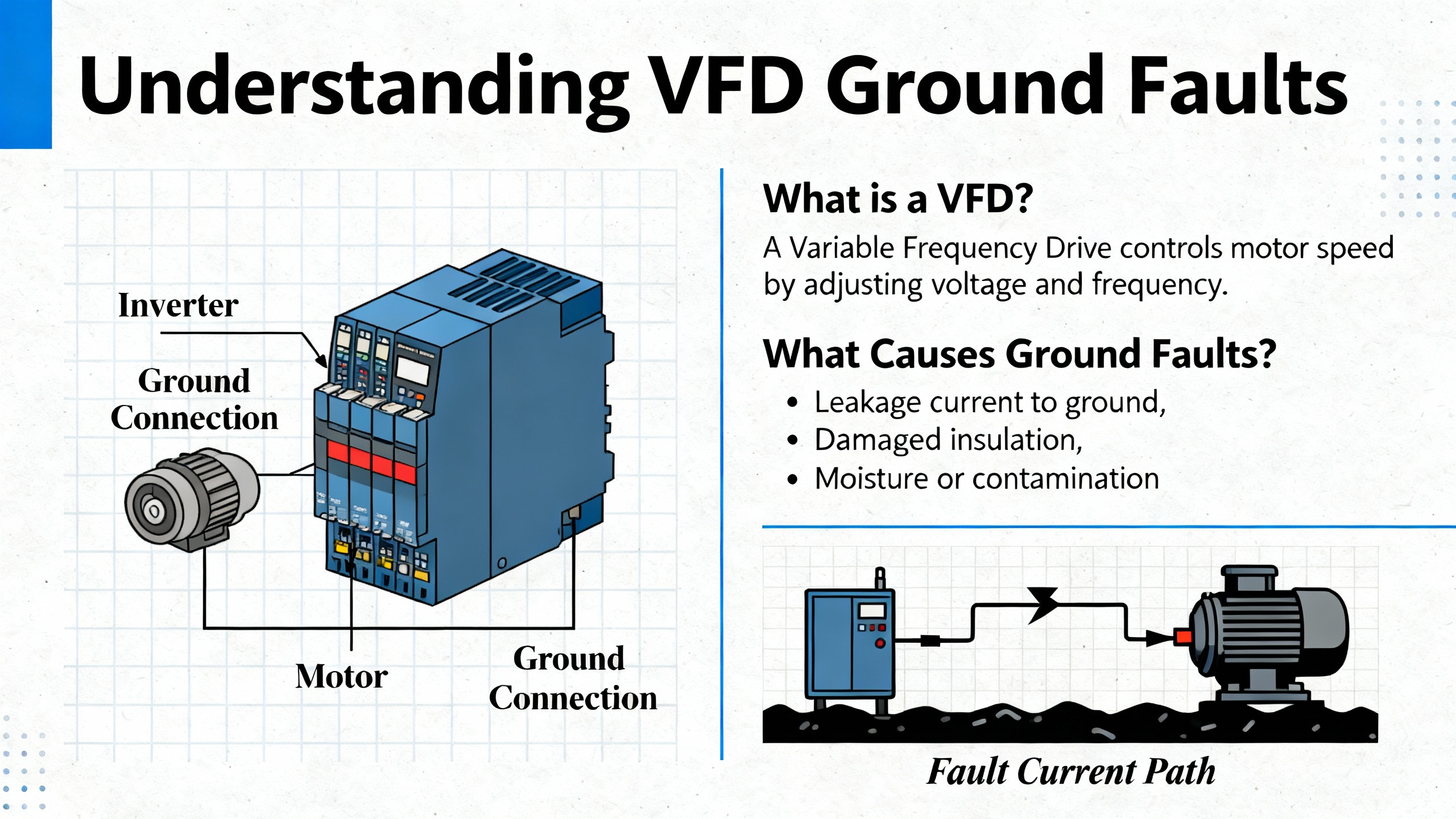
A variable frequency drive controls AC motor speed and torque by adjusting the frequency and voltage of its output. That conversion process brings a lot of benefits for energy efficiency and process control, but it also changes how ground faults behave.
EECO explains a ground fault in a VFD system as current “bleeding” to ground from any point in the motor circuit instead of returning through the intended conductor. The drive’s HMI may show a code such as “GF” or “ground fault” or “earth leakage” when it detects that imbalance. Joliet Electric notes that these ground fault trips are protection actions designed to shut the drive down before the power output section is damaged by faults in the motor cables or the motor itself.
Several important points follow from the way drives are built and from how vendors describe these trips. First, VFDs are not intended to be used as primary circuit protection devices. EECO emphasizes that a VFD offers only limited protection for its own components and that ground fault detection is just one internal protective function. Second, many drives do not trip on ground fault until the fault current is already a significant fraction of rated output current. Joliet Electric points out that typical drives trip only when ground fault current reaches roughly half of the rated output current. By the time you see that fault, a serious insulation breakdown in leads or windings has usually already occurred.
From a practical standpoint, a ground fault code from the drive should therefore be treated as evidence of a real electrical problem until you prove otherwise, not as an annoyance to be cleared and ignored.
Ground Fault vs Overcurrent and Other VFD Faults
Ground faults are just one class of VFD trip. Automation Electric describes others such as overvoltage, undervoltage, overcurrent, motor overload, and overtemperature, all of which point to different root causes. Ground fault or earth leakage codes are different because they indicate current taking a path to ground that was never intended. That can be through degraded motor insulation, damaged cable jackets, contamination in junction boxes, or internal failures in the drive’s sensing circuitry.
In contrast, overcurrent faults are triggered when current exceeds around two and a half times the drive’s rating, often due to rapid changes in load torque, mechanical binding, or electrical issues between phases. Overvoltage and undervoltage faults point toward supply quality problems or DC bus issues. Those matter, but they do not carry the same implication that a conductive path has formed where none should exist.
Understanding that distinction is useful when you prioritize troubleshooting. A ground fault trip deserves immediate inspection of insulation, cabling, and grounding paths before you consider returning the drive to service.
Grounding Basics You Cannot Get Wrong
In every serious ground fault investigation I have been involved in, the conversation comes back to grounding. The details are technical, but a few core concepts from long‑time practitioners and standards‑based guidance will keep you on safe ground.
A seasoned contributor on Control.com, drawing on decades of work under the US NEC and NFPA practice, makes a critical distinction between equipment ground and system ground. The equipment ground is the green or green‑yellow conductor that provides the low‑resistance path back to the source to clear ground faults. It is what ensures exposed metal parts do not sit at a dangerous potential during a fault. The system ground is the bond between neutral and earth at the service or transformer, intended mainly for reference and for dissipating transients.
A common and dangerous mistake is to treat a standalone ground rod driven into the floor and tied only to a machine as a substitute for the equipment grounding conductor. That rod is not an equipment ground. Using it in place of a proper equipment grounding conductor can leave the machine frame floating at hazardous voltage and can be fatal.
Pumps & Systems, discussing VFD grounding in pumping applications, reinforces that effective VFD grounding requires a low‑impedance protective earth network that directly bonds the drive frame and motor frame. Modern pulse‑width‑modulated drives generate high‑frequency common‑mode noise. Without a solid bond between drive and motor, the motor shaft voltage can rise above safe limits, accelerating bearing damage and placing stray voltages throughout the VFD circuit.
There is also a strict rule I do not allow anyone on my teams to break: noise mitigation must never involve lifting the equipment ground. The Control.com discussion is explicit on this. The green equipment grounding conductor must always run with the power conductors, including for VFD‑fed motors, and must never be disconnected in an attempt to “fix” interference or nuisance trips. If you defeat the ground, you remove the very path that needs to carry fault current safely away.
In control panels, experienced practitioners avoid daisy‑chaining grounds. Each PLC chassis, drive, and sensitive device gets its own dedicated equipment grounding conductor back to the cabinet’s ground bus, and that cabinet is bonded to the plant equipment ground with a robust conductor. That approach reduces potential differences between devices, improving both safety and noise behavior.
For protection against ground faults, you also have to consider devices like ground‑fault relays, ground‑fault circuit interrupters, and residual current devices. Littelfuse notes that conventional 50 or 60 Hz personnel‑protection devices and basic GFCIs are designed for near‑sinusoidal currents and can struggle with the non‑sinusoidal waveforms coming out of modern VFDs. Specialized ground‑fault relays built for drives use true RMS measurement and filtering to distinguish normal high‑frequency leakage from actual faults. That distinction becomes important when we talk about nuisance tripping.
True Ground Fault or Nuisance Trip?
Before you start pulling motors and megger‑testing every conductor in sight, it pays to decide whether you are dealing with a genuine ground fault or a protection device that is reacting to normal leakage currents from VFD operation.
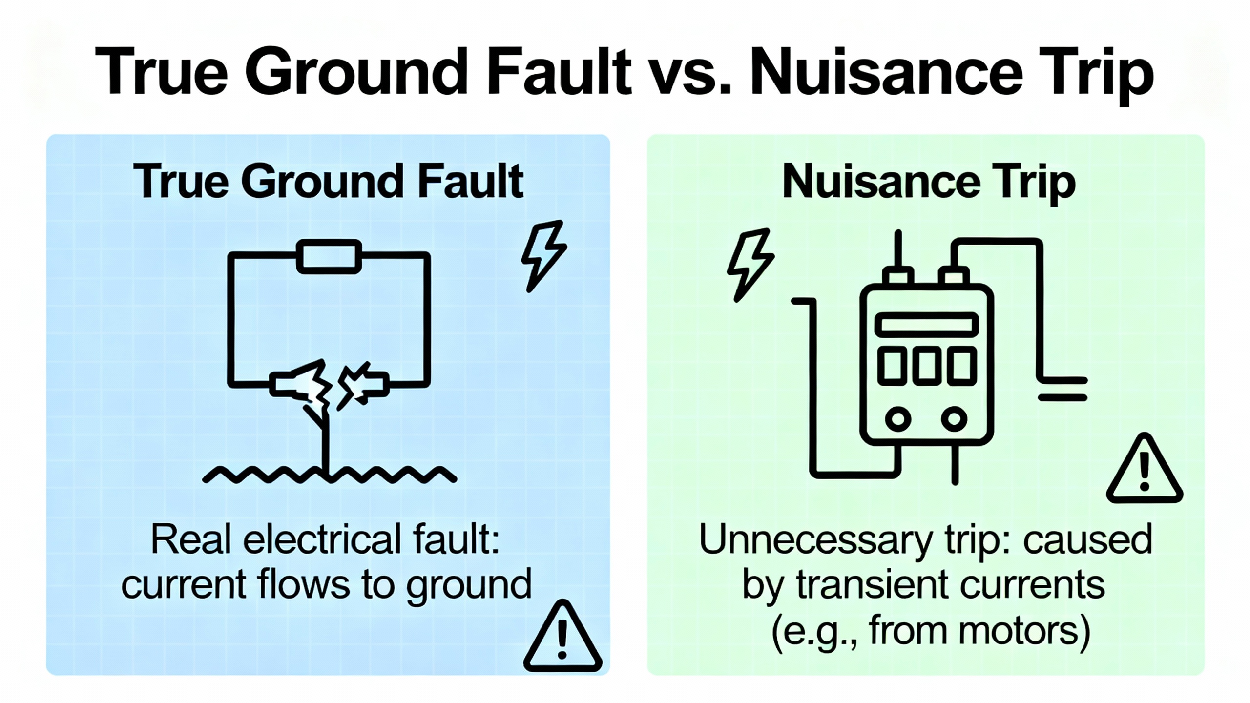
A ground fault in the classic sense is an unintended connection from a live conductor to ground. KEB describes the difference between low‑resistance faults, which produce very high currents that quickly trip breakers and fuses, and high‑resistance faults, which may let hazardous voltage sit on equipment while staying below overcurrent thresholds. Either way, the current is flowing where it should not, and the risk is real.
At the same time, KEB points out that not all ground currents indicate faults. In any real three‑phase system, there is capacitance between conductors and grounded structures. The high‑frequency switching in a VFD reduces the impedance of that capacitance and drives higher leakage currents to ground even when the system is perfectly healthy. When those VFD‑induced currents flow through an upstream GFCI or residual current device, the protective device may interpret them as a fault and trip, even though the motor, cable, and drive insulation are intact.
This is how you end up with nuisance trips where the VFD reports no ground fault internally, but upstream RCDs or GFCIs open whenever a group of drives accelerates. According to KEB’s discussion, EMC filters and capacitors inside the drives provide a low‑impedance return path for high‑frequency currents and reduce what leaks upstream, but every added filter also increases supply‑side leakage that flows through the RCD. In large multi‑drive installations, these leakages add together and can exceed the trip threshold of a conventional device.
So when you see a “ground fault” event, your first diagnostic step is to identify where it came from. If the VFD’s own fault log shows a ground fault or earth leakage code, you are dealing with the drive’s internal view of leakage on its output. If only the upstream RCD or GFCI trips while the drive itself shows no ground fault code, you may be facing a nuisance trip caused by cumulative leakage or by the frequency response of the protective device.
The isolation process for each case is different. For the rest of this article I will focus first on true faults reported by the drive, then come back to how you deal with nuisance tripping in RCDs and similar devices.
Stepwise Isolation: Motor, Cable, or Drive?
Once you have confirmed that the VFD itself is reporting a ground fault, the main question is simple: where is the fault path located? In practice, you need a disciplined sequence that avoids guesswork, protects people, and avoids further damage to equipment.
Preparation: De‑energize and Inspect
Automation Electric stresses that early warning signs such as excess heat, condensation, and erratic performance should not be ignored, because these often precede trips or failures. Before you start any testing, de‑energize the drive, follow your lockout and tagout procedures, and allow time for the DC bus capacitors to discharge.
With power verified off, open the drive and motor termination areas and perform a careful visual inspection. Automation Electric recommends looking for soot, burn marks, discoloration, or cracking on components. Any such evidence of overheating or damage is enough to justify replacing those parts before you go further. Check motor junction boxes and cable glands for moisture, contamination, or signs that insulation has been cooked by previous overloads.
First Diagnostic Split: Does the Fault Persist with the Motor Disconnected?
EECO and Joliet Electric both recommend essentially the same first test because it cleanly separates issues in the drive from those in the motor and cable.
With power off, completely disconnect the output leads from the drive to the motor. Make sure the loose cable ends are safely isolated. Then power up the drive with no motor connected and issue a run command under conditions similar to the ones that produced the original fault.
If no ground fault occurs with the output open, the evidence points toward the motor or the motor leads as the source. If the ground fault code appears even though the drive has no load connected, the problem is likely internal to the drive. EECO describes this as the point where you “go to the bullpen and get a replacement,” because an internal failure in the ground‑fault sensing or output stage is rarely economical to repair on site. Joliet Electric mentions that defective current transformers used to sense output current are one possible internal cause.
When the Motor or Cable Is Suspect
If disconnecting the motor clears the fault, you then need to decide whether the weakness lies in the cabling or in the motor windings themselves. Both EECO and Joliet Electric describe how faults can arise in each.
Cable‑related ground faults typically result from insulation damage. The EECO article lists several causes: insulation melting after an overcurrent event, physical damage during installation such as pulling cable that is not flexible enough and forcing it to bend sharply, and external damage such as animals chewing on the conductors. Joliet Electric adds that the fast dv/dt pulses from a VFD can, over time, raise voltages above the cable’s corona inception level, ionize air pockets, and progressively destroy insulation until a conductor finally shorts to ground.
Motor windings can fail in similar fashion. EECO points to voltage spikes, overheated windings, aged insulation, and conductive contamination inside the motor that bridges windings to the grounded frame. Joliet Electric explains that high‑frequency pulses and resonance between drive, cable, and motor can induce stray circulating currents and extra heat in the motor, accelerating insulation breakdown. When winding insulation degrades enough, the winding shorts to the grounded motor frame and the drive sees a ground fault.
From a practical troubleshooting standpoint, you should isolate the motor from the cable and test each separately. Disconnect the cable from the motor terminals. Using a suitable megohmmeter, test insulation resistance between each conductor and ground, and between conductors, for both cable and motor. EECO explicitly recommends a megohmmeter for checking whether wire insulation is the cause of the ground fault. Follow manufacturer limits for acceptable values and remember never to megger the drive itself. Drives contain sensitive electronics that are not intended for that kind of high‑voltage test.
When you find compromised insulation in a motor, EECO is clear that the motor will need to be rewound or completely replaced. There is no safe way to “patch” winding insulation in the field. Damaged cables should likewise be repaired or replaced rather than left in service. Joliet Electric underscores that, because many drives only trip on ground fault when the fault current is already a large fraction of the rated current, the underlying damage is usually severe by the time you see the trip.
Input‑Side Protection and Upstream Devices
While the VFD’s ground fault function is aimed at the output side, Joliet Electric reminds us that faults on the input side require external protection. Input‑side ground‑fault protection must be provided by upstream ground‑fault relays and appropriate fuses or breakers that can detect both AC and DC fault components. On solidly grounded systems, conventional overcurrent devices usually clear phase‑to‑ground faults, but Joliet Electric notes that fault currents can become very high, so high‑speed fuses are recommended to keep peak let‑through current within what the drive’s power section can tolerate.
On resistance‑grounded and ungrounded systems, the situation is more nuanced. Joliet Electric points out that the drive’s EMI filter is bonded to ground for noise control. In some system configurations, a system ground fault can create destructive loops through that filter, so manufacturers may require the filter to be disconnected. In that case, external ground‑fault relays contribute mainly to personnel safety and do not guarantee complete drive protection. It is another reason why understanding the grounding scheme of the facility is not optional when you troubleshoot ground faults.
Managing Nuisance Tripping with RCDs, GFCIs, and VFD Leakage
If your site uses residual current devices, GFCIs, or similar protective devices, a good ground fault strategy has to balance real‑fault sensitivity against tolerance for normal VFD leakage.
High‑resistance grounding, described in KEB’s analysis, uses a resistor between a transformer’s wye neutral and earth to limit ground‑fault current. That approach reduces arc‑flash energy and voltage dips during faults. Residual current devices, in turn, detect imbalances between conductors through a current transformer and trip when the net current to ground exceeds a threshold. In wet locations and near grounded metal enclosures, codes in the United States have required GFCI protection for decades to protect personnel from shock.
However, VFDs complicate the picture. KEB explains that high‑frequency leakage currents driven by the inverter output and by internal capacitors are normal in VFD applications and can be misinterpreted by RCDs as ground faults. Additionally, Littelfuse notes that conventional ground‑fault and GFCI devices designed for pure 50 or 60 Hz operation may not measure PWM currents correctly and can either fail to detect a fault or trip when they should not.
Several practical strategies emerge from their guidance. First, when nuisance tripping is an issue, KEB recommends grouping multiple drives behind a single appropriately sized EMC filter so that high‑frequency currents have a clear return path back to the drives rather than through the RCD. This can significantly reduce the cumulative leakage that flows through the RCD and can postpone or avoid nuisance trips. When the combined drive current exceeds a single filter’s rating, drives can be split into smaller groups, each with its own branch circuit, filter, and RCD.
Second, some drives provide the option to disable their internal input filters when leakage is a concern. KEB cites drive families that support this and notes that pairing such drives with “intelligent” residual current devices that use frequency‑dependent tripping curves allows the system to tolerate higher leakage at high frequency while still reacting quickly to dangerous low‑frequency ground faults. Devices from manufacturers such as Doepke are examples of this concept.
Third, Littelfuse emphasizes that when drives are involved, it is often better to use ground‑fault relays and sensors specifically rated for VFD applications. These devices use true RMS sensing and appropriate filtering so they can tell the difference between standing leakage and genuine faults, and Littelfuse recommends installing their sensors so that the current transformer encloses all phase conductors but not the protective earth conductor. Any imbalance then represents current returning on ground instead of the intended conductors, which is exactly what you want to detect.
The tradeoff is straightforward. Higher sensitivity and simple, low‑cost GFCIs offer strong personnel protection but may be unusable in systems with many VFDs because of nuisance trips. More specialized ground‑fault relays and filters cost more and require careful design, but they give you a higher level of discrimination between normal leakage and real faults and reduce unplanned downtime. In industrial installations, that trade tends to pay for itself quickly.
Design and Installation Practices to Prevent Ground Faults
Fixing a ground fault once is good. Designing and maintaining systems so you rarely see one is better. The research notes and field experience point toward a set of practices that significantly reduce the likelihood of recurring ground fault problems.
Proper Grounding and Bonding
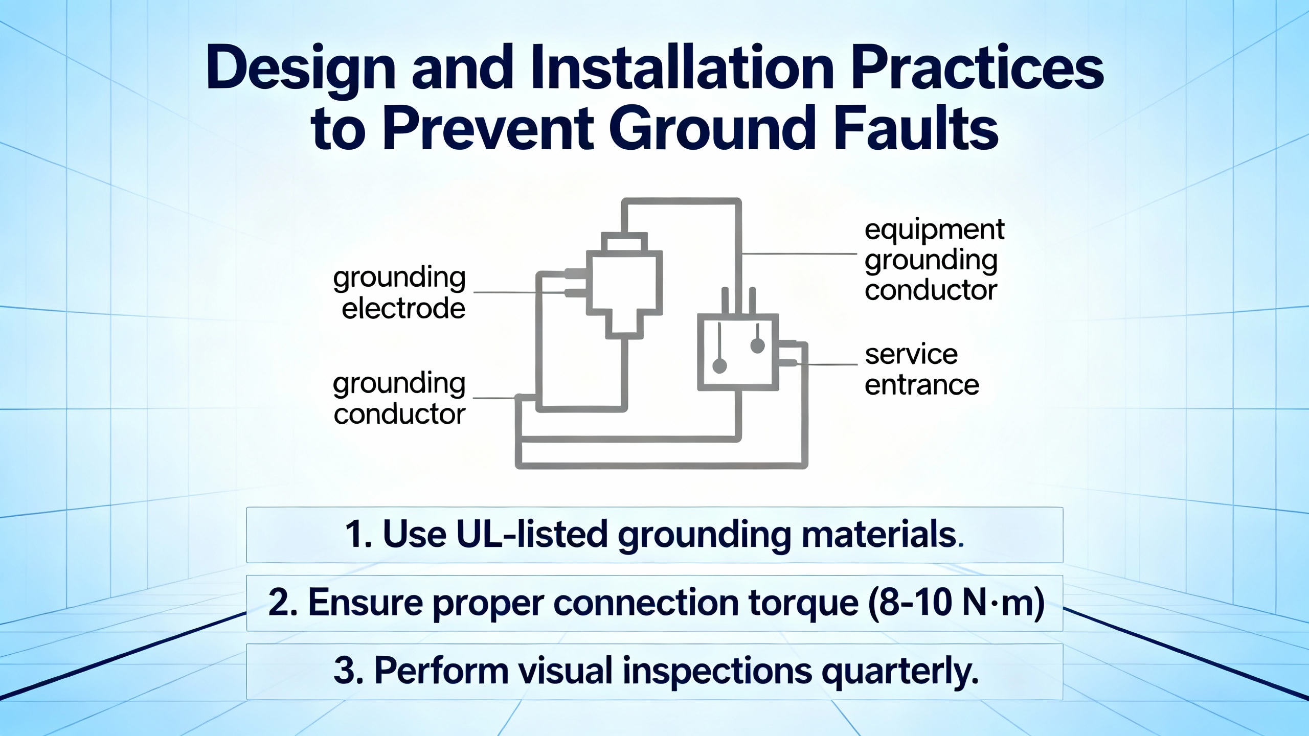
Pumps & Systems stresses the need for a dedicated low‑impedance protective earth network for VFDs, distinct from the “true earth” paths through building steel or water piping that exist primarily for safety fault clearing. For drives, you want a direct, low‑impedance bond between the drive frame and the motor frame so that common‑mode noise currents and any fault currents have a defined path back to the source.
The detailed grounding discussion on Control.com adds that each processor‑based chassis, drive, and rectifier should have its own equipment grounding conductor back to the panel ground bus, and that the cabinet itself should be well bonded to the plant ground grid. Neutral‑to‑ground bonds must be made once at the service entrance and not repeated in downstream panels, because multiple bonds create noise and shock risks. For shielding, the same practitioners warn that shielding schemes need to be coordinated with any ground‑fault protection devices so that shield connections do not bypass ground‑fault sensors or create nuisance trips.
Taken together, the message is that grounding is not an afterthought or a “best effort” detail. It is a designed subsystem that has to support both safety and noise performance, especially when VFDs are involved.
Cable Selection, Routing, and EMC
Several sources stress the importance of using cables and routing methods suitable for VFD duty. Joliet Electric notes that long cable runs and standard insulation can be vulnerable to the fast dv/dt edges and resonance in a drive–cable–motor system, which accelerates insulation breakdown. TSL Group’s guidance on VFD installation, although not limited to ground faults, explains that using standard power cable instead of VFD‑rated cable can result in electromagnetic interference, voltage reflection, and insulation breakdown, particularly on long runs or high‑frequency applications.
TSL Group recommends using shielded, VFD‑rated cable for motor connections, sized correctly for the drive current, and routing power and signal cables separately while keeping cable runs as short as possible. Control Engineering adds that VFD output cables benefit from screened construction with proper shield terminations and that input, output, and control wiring should be run in separate metallic conduits with careful attention to physical separation. These practices reduce both the electrical stress on insulation and the amount of radiated noise that can sneak into control circuits and protection devices.
Environmental Control and Thermal Management
Canroon’s discussion of VFD failures highlights how environment drives reliability. Most VFDs are designed to operate at full capacity up to a specified ambient temperature, often around 104°F, and running above that with poor ventilation leads to overheating, component damage, and control issues, including fault codes. Moisture and humidity cause shorts, corrosion, and overheating; dust and debris clog vents and insulate heat sinks.
TSL Group points out that many drives fail not because of misuse but because of poor environmental planning. Heat, dust, and corrosive atmospheres degrade performance or cause total failure. Their recommendations include selecting appropriate enclosure ratings, providing adequate ventilation, keeping vents unobstructed, and cleaning dust and debris from vents and fans regularly. These practices are directly relevant to ground fault prevention because moisture and contamination in cable terminations and motor junction boxes are classic paths to leakage and faults.
Protection Coordination and Device Selection
Littelfuse and Bender both emphasize that ground fault protection in industrial facilities must be designed, not improvised. In high‑stakes sectors such as oil and gas, Bender notes that ground faults can lead to equipment damage, power interruptions, and electrical shock hazards, any of which may be disastrous in those environments. Ground‑fault schemes in such facilities are engineered to maintain electrical reliability while ensuring personnel and asset safety.
For VFD installations, that means coordinating the drive’s internal protection with upstream fuses, breakers, and ground‑fault relays in a way that detects and clears faults quickly but does not shut down wide sections of the plant unnecessarily. Littelfuse recommends setting ground‑fault pickup levels above expected standing leakage but low enough to catch genuine faults, and coordinating time delays so that transients and normal capacitance charging currents do not cause trips. Input‑side devices should have adequate interrupt ratings and appropriate trip curves to protect both the drive and the system during high‑current events.
If you are working on resistance‑grounded or ungrounded systems, the guidance from Joliet Electric and others is that EMI filters and ground‑fault protection have to be evaluated together, because the filter’s connection to ground can create unwanted paths for system‑level faults. In some cases the manufacturer may require removing internal filters and relying on external relays for personnel protection, accepting that drive protection against all fault modes is not complete.
Maintenance and Monitoring
Preventive and predictive maintenance close the loop. Canroon and CM Industry Supply emphasize that many VFD faults can be avoided by regular inspection and cleaning, monitoring of fault logs, and timely replacement of aging components such as fans and capacitors. Control Engineering notes that monitoring performance metrics such as temperature, voltage, and current anomalies can reveal impending problems, allowing a predictive maintenance strategy instead of reactive firefighting.
With respect to ground faults, this means scheduling periodic insulation resistance tests for motors and critical cables, inspecting motor junction boxes for moisture and contamination, checking terminations for looseness or overheating, and logging every ground‑fault event with context such as load, speed, and operating conditions. These records often reveal patterns that point directly at the root cause long before catastrophic failure.
When to Repair, When to Replace
One of the difficult decisions in a ground fault investigation is whether to repair or replace the affected equipment. The notes from EECO and Joliet Electric provide a straightforward framework.
When motor windings are compromised and you confirm low insulation resistance to ground, the options are to rewind or replace the motor. EECO is clear that if the windings are compromised, the motor needs a rewind or complete replacement. Rewinding may be appropriate for larger or special‑purpose machines where the mechanical package is valuable; replacement may be more economical for standard frame motors.
For cables with insulation damage, there is little justification for piecemeal fixes in critical applications. Joliet Electric’s explanation of how PWM stress gradually destroys insulation makes it clear that once a cable has progressed to the point of a hard ground fault, similar degradation may exist in adjacent sections even if it has not yet failed. Replacing the run or at least the damaged sections is normally the prudent choice.
For drives that continue to show ground fault codes with their outputs disconnected, both EECO and Joliet Electric point toward internal sensor or power device failures. In most industrial settings, such drives are swapped out rather than repaired in the field. The key is to confirm that the replacement is installed with the grounding and cabling practices described earlier, so that the same sequence of stress does not damage the new unit.
Short FAQ
What is the drive actually detecting when it shows a ground fault? The drive is detecting current that is returning to the source through unintended paths to ground on its output side. According to EECO and Joliet Electric, that current may be flowing through damaged motor or cable insulation, contamination inside the motor or junction box, or internal failures in the drive’s current sensing circuitry. Many drives only trip when that leakage reaches a significant fraction of rated output current, which means real damage has usually already occurred.
Can I rely on the VFD alone for ground fault protection? No. EECO points out that VFDs provide only limited internal protection and are not designed to serve as the primary circuit protection device. Joliet Electric explains that the drive’s ground fault function covers the output side, but input‑side faults must be handled by external ground‑fault relays and properly rated fuses or breakers. Specialized ground‑fault relays from companies such as Littelfuse and Bender are often used to provide comprehensive protection at the system level.
Is it ever acceptable to disable ground fault protection to keep production running? The guidance across multiple sources is that bypassing ground fault protection is not acceptable. Joliet Electric, in particular, warns against bypassing or disabling ground fault protection just to continue operation, as this exposes the drive and connected equipment to catastrophic damage and increases safety hazards for personnel.
Why does my upstream GFCI or RCD trip when the VFD runs, even when the drive does not show a ground fault code? KEB explains that VFDs generate high‑frequency leakage currents through cable capacitance and EMC filters, and those currents can flow through upstream GFCIs or residual current devices. Conventional devices that are sensitive to small imbalances at all frequencies may interpret this normal leakage as a fault and trip. Solutions recommended by KEB and Littelfuse include using filters and grounding schemes that provide a defined high‑frequency return path back to the drives, grouping drives behind suitable EMC filters, and choosing RCDs or ground‑fault relays whose sensing and tripping curves are designed to work with VFD waveforms.
Closing
Ground fault trips on a VFD are one of those problems that separate quick reset‑and‑hope habits from disciplined engineering. The sources cited here and real‑world experience all converge on the same pattern: treat every ground fault trip as a serious event, isolate whether the issue is in the motor, cable, or drive, verify that your grounding and protection are engineered rather than improvised, and then fix the underlying weakness rather than the symptom. Done that way, a ground fault error becomes not a recurring headache but an opportunity to harden your system and demonstrate that you are the kind of project partner who leaves the plant in better shape than you found it.

References
- https://www.plctalk.net/threads/ground-fault-on-vfd.112626/
- https://www.pumpsandsystems.com/best-practices-vfd-grounding
- https://automationelectric.com/how-to-troubleshoot-problems-with-a-vfd/
- https://www.canroon.com/Industry-Insights/How-to-Avoid-Common-Frequency-Regulation-Failures-in-VFDs
- https://cmindustrysupply.com/blogs/preventing-vfd-faults-and-failures-a-comprehensive-guide
- https://www.controleng.com/preventing-vfd-faults-and-failures/
- https://eecoonline.com/inspire/what-is-a-ground-fault-in-a-vfd
- https://www.justanswer.com/hvac/3zwrg-having-problems-vfd-showing-ground-fault-problems.html
- https://www.littelfuse.com/assetdocs/ground-fault-protection-with-vfds?assetguid=2242ad15-3bf5-4fd5-9db6-dadaa83afa55
- https://smartd.tech/vfd-leakage-current-ground-fault-protection/
Keep your system in play!
Top Media Coverage
Categories


Related articles Browse All
-
 amikong NewsSchneider Electric HMIGTO5310: A Powerful Touchscreen Panel for Industrial Automation2025-08-11 16:24:25Overview of the Schneider Electric HMIGTO5310 The Schneider Electric HMIGTO5310 is a high-performance Magelis GTO touchscreen panel designed for industrial automation and infrastructure applications. With a 10.4" TFT LCD display and 640 x 480 VGA resolution, this HMI delivers crisp, clear visu...
 -
 BlogImplementing Vision Systems for Industrial Robots: Enhancing Precision and Automation2025-08-12 11:26:54Industrial robots gain powerful new abilities through vision systems. These systems give robots the sense of sight, so they can understand and react to what is around them. So, robots can perform complex tasks with greater accuracy and flexibility. Automation in manufacturing reaches a new level of ...
 -
 BlogOptimizing PM Schedules Data-Driven Approaches to Preventative Maintenance2025-08-21 18:08:33Moving away from fixed maintenance schedules is a significant operational shift. Companies now use data to guide their maintenance efforts. This change leads to greater efficiency and equipment reliability. The goal is to perform the right task at the right time, based on real information, not just ...


- Q&A
- Policies How to order Part status information Shipping Method Return Policy Warranty Policy Payment Terms
- Asset Recovery
- We Buy Your Equipment. Industry Cases Amikong News Technical Resources Why choose us
- ADDRESS
-
 32D UNITS,GUOMAO BUILDING,NO 388 HUBIN SOUTH ROAD,SIMING DISTRICT,XIAMEN
Leave Your Comment