
-
Please try to be as accurate as possible with your search.
-
We can quote you on 1000s of specialist parts, even if they are not listed on our website.
-
We can't find any results for “”.
Allen-Bradley 1794-IE8 FLEX I/O Equivalent Modules: A Pragmatic Cross-Reference Guide
When someone calls me from a plant floor asking for an “equivalent” to an Allen-Bradley 1794-IE8, what they really mean is this: “Give me a drop‑in replacement that my PLC, wiring, electricians, safety team, and auditors will all accept without surprises.” That is a higher bar than just matching eight analog channels on a spec sheet.
This guide looks at the 1794-IE8 in context, using Rockwell Automation documentation and field-proven wiring and installation practices. The goal is to help you reason about equivalents and near-equivalents in a disciplined way, not to guess part numbers. I will stay grounded in published information from Rockwell Automation, official manuals, and trusted secondary sources such as Anadi Automation and Manuals Plus, and layer practical, project-level advice on top.
Where the 1794-IE8 Fits In Your Architecture
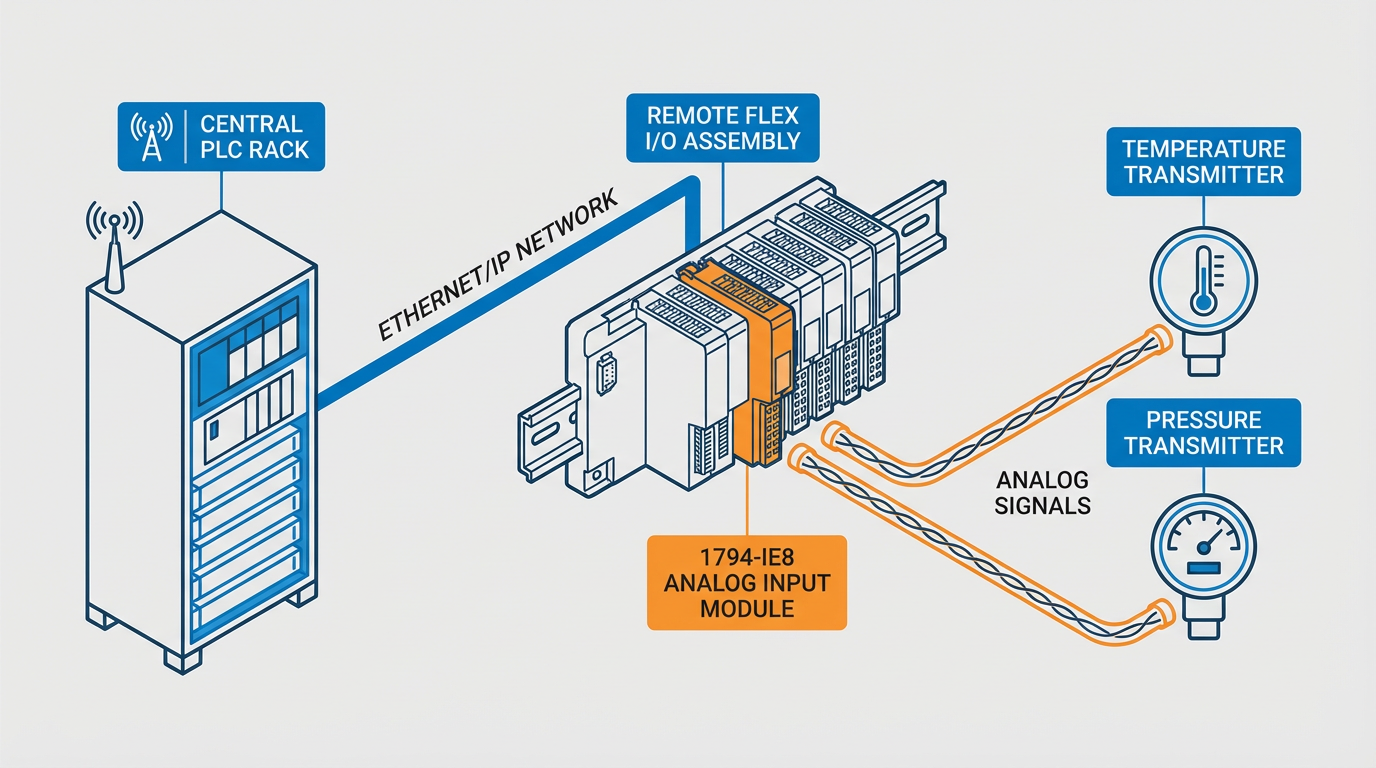
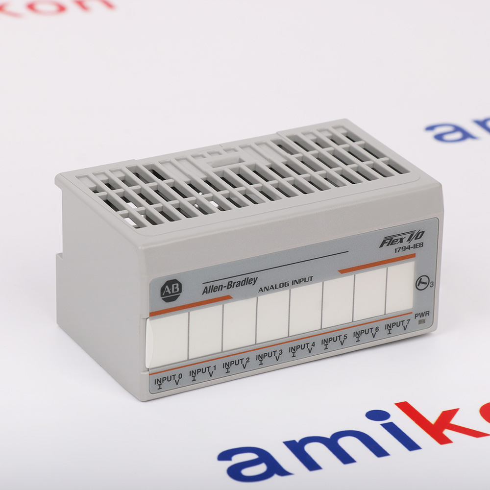
The 1794-IE8 is an eight-channel analog input module in the Allen-Bradley FLEX I/O family. FLEX I/O is Rockwell’s modular distributed I/O platform: terminal bases, I/O modules, and a network adapter share a DIN rail, so you can place I/O close to the process and avoid running large bundles of analog cable back to a central rack.
An analog input module like the 1794-IE8 takes continuous real‑world signals—current or voltage representing temperature, pressure, level, flow, or similar variables—and converts them into digital values your controller can use. Sources such as TCI Supply and DoSupply emphasize that the 1794-IE8 is built specifically for this role, with eight single‑ended, user‑configurable channels designed for industrial transmitters and instruments.
In practice, you see the 1794-IE8 wherever somebody wanted a compact multi-channel analog front end tied into ControlLogix, CompactLogix, or another Rockwell controller via a FLEX adapter on EtherNet/IP, ControlNet, or DeviceNet. Anadi Automation’s guide on the 1794-IE8 highlights typical applications such as monitoring temperature, pressure, voltage, and current with real‑time trending and historical logging on the PLC or historian side.
Before you can talk meaningfully about “equivalents,” you have to pin down what makes the 1794-IE8 what it is: its signal ranges, accuracy, update behavior, power and environmental limits, safety approvals, and mechanical integration into the FLEX ecosystem. That is what the next sections focus on.
Key 1794-IE8 Specifications You Must Match
Rockwell Automation technical data, echoed by distributors such as DoSupply and McNaughton‑McKay, give a clear picture of the 1794-IE8’s capabilities. When I evaluate an equivalent, these are the parameters I insist on matching or deliberately improving.
Electrical performance and signal handling
The 1794-IE8 provides eight single‑ended analog input channels. According to DoSupply’s data, each channel can be configured for current or voltage, with typical supported ranges including 0–20 mA and 4–20 mA current inputs, plus 0–10 V and ±10 V voltage inputs. That mix is exactly what most process transmitters, indicators, and controllers expect.
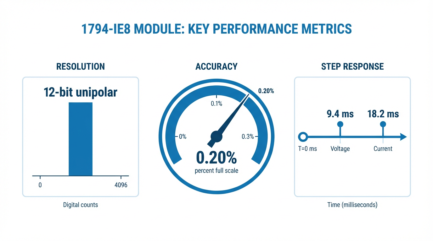
The module uses successive-approximation A/D conversion, with 12-bit resolution in unipolar mode and 11 bits plus sign in bipolar mode. For voltage inputs, resolution is around 2.56 mV per count in unipolar operation and 5.13 mV per count in bipolar mode. For current inputs, resolution is roughly 5.13 microamps per count. Data is stored as left‑justified 16‑bit two’s‑complement values, which is what Rockwell controllers expect and what your existing logic already assumes.
Conversion performance is also spelled out. DoSupply cites a conversion rate of about 256 microseconds on all channels, with a step response to 63 percent of final value on the order of 9.4 milliseconds for voltage inputs and 18.2 milliseconds for current signals. Accuracy at room temperature is about 0.20 percent of full scale, with a modest accuracy drift per degree of temperature change. For most process applications—flow, pressure, level, temperature—that combination of resolution, accuracy, and response is more than adequate.
When you hunt for an equivalent module, these are not minor details. If you drop to 10‑bit resolution, or accept much larger drift, or a far slower update rate, you can absolutely feel it in loop performance and in historian data quality.
Power, thermal, and mechanical profile
On the power side, Rockwell’s data and Manuals Plus are consistent: the 1794-IE8 expects an external DC supply at 24 V nominal, with an operating range roughly from 10.5 to 31.2 V DC. Supply current at 24 V is about 60 mA, and maximum module power dissipation is around 3 W, which translates to roughly 10.2 BTU per hour of heat. FLEXbus current draw is modest, around 15 mA.
Physically, DoSupply notes dimensions of about 3.7 by 2.1 by 3.18 inches, in an open-style enclosure that mounts on a FLEX terminal base such as 1794-TB2, 1794-TB3, 1794-TB3S, 1794-TB3T, or 1794-TB3TS. If you are targeting a truly “drop‑in” equivalent, both the power envelope and the mechanical interface matter. Undersizing the power supply or overlooking heat dissipation in a densely packed cabinet is an easy way to create intermittent failures that only show up on hot afternoons.
Environmental and safety envelope
For environmental and safety parameters, the authoritative source is Rockwell Automation’s 1794 analog module user manual (1794-UM002) as well as the formally mirrored content on Manuals Plus.
These documents make several important points. The 1794-IE8, along with its analog siblings, is designed for industrial environments with Pollution Degree 2 and Overvoltage Category II. It is intended for use at altitudes up to roughly 6,562 ft without derating. The unit itself is an open-type device and must be mounted indoors within a suitable enclosure that meets appropriate protection standards; Rockwell and Manuals Plus reference flame-retardant enclosures with ratings such as 5VA and ingress protection at or above IP54 for Zone 2 hazardous locations, aligned with standards like NEMA 250 and EN or IEC 60529.
Temperature ratings are also explicit. Rockwell technical data and distributors report an operating range extending down to about −4°F and up to 131°F, although some distributor listings emphasize a narrower 32°F to 131°F band consistent with typical control room environments. Storage temperatures are wider, down to −40°F and up to about 185°F.
Hazardous-location approvals are one area where equivalence really matters. Rockwell documentation shows that 1794-IE8, together with modules like 1794-OE4 and 1794-IE4XOE2, carries UKEX and ATEX Zone 2 approvals, IECEx, and North American Class I, Division 2 certifications. The 1794-IE8, for example, is labeled with protection type Ex ec IIC T4 Gc, and its companions are Ex nA IIC T4 Gc. In North America, Class I, Division 2, Groups A, B, C, and D are supported. The temperature code is typically T5 for the 1794-IE8 and T4 or T4A for related modules; for a given panel, you must always design to the most restrictive (lowest) T‑code among all components.
Any module you treat as an “equivalent” in a hazardous area has to carry matching or better approvals and compatible temperature codes, or you will undermine your zoning design and your compliance posture.
Summary table: what defines a meaningful equivalent
To frame the cross-reference discussion, here is a concise view of the 1794-IE8’s defining attributes and why they matter when you look for substitutes. All values are taken or derived from Rockwell Automation technical data and the distributor summaries already mentioned.
| Attribute | 1794-IE8 value or behavior | Why it must be matched or understood |
|---|---|---|
| Function | Eight-channel analog input for current and voltage | Core role; any equivalent must serve the same function |
| Channels | Eight single-ended inputs | Drives how many field devices each module can serve |
| Signal types and ranges | Typical 0–20 mA, 4–20 mA, 0–10 V, ±10 V | Determines compatibility with existing transmitters and instruments |
| Resolution | About 12 bits unipolar, 11 bits plus sign bipolar | Affects measurement granularity and noise floor |
| Accuracy at room temperature | About 0.20 percent of full scale | Drives loop performance and reporting quality |
| Update characteristics | About 256 microseconds conversion; step response in ms range | Impacts control loop responsiveness and trend fidelity |
| Supply and dissipation | 24 V DC nominal, around 60 mA; about 3 W and 10.2 BTU/hour | Impacts power budgeting and thermal design in the panel |
| Mechanical integration | FLEX I/O module on 1794 terminal base types | Determines whether it will physically plug into the existing base |
| Environmental limits | Operating roughly −4°F to 131°F, Pollution Degree 2 | Ensures reliability in the actual ambient conditions |
| Hazard approvals and T‑codes | Zone 2, Class I Div 2, Ex ec / Ex nA, T‑codes T5 or similar | Essential for legal use in classified areas |
Once you understand this envelope, you are ready to look at Rockwell’s own closely related modules and then at broader cross-reference strategies.
Close Rockwell FLEX I/O Relatives and Near-Equivalents
Within the FLEX I/O family, the most natural “equivalents” or companions to the 1794-IE8 are the analog modules that share its mechanical platform, installation rules, and safety approvals. Rockwell Automation’s 1794-UM002 manual, echoed by Manuals Plus, covers three Series B analog modules together: the 1794-IE8 (analog input), the 1794-OE4 (analog output), and the 1794-IE4XOE2 (combination input/output).
All three are physically similar, mount on the same style of FLEX terminal bases, share the same 24 V DC power philosophy, and carry comparable environmental and hazardous-location ratings. In other words, the family was designed to be mixed on the same DIN rail under the same adapter and the same certification umbrella.
For a cross-reference practitioner, that matters. If your project spec simply calls for “FLEX I/O analog module” without distinguishing direction, or if you are rebalancing I/O counts in an existing panel, you can treat these three as a coherent family and reallocate inputs and outputs between them without rethinking enclosure design, wiring practices, or hazardous-location approvals.
The 1794-IE4XOE2 in particular can sometimes be used as a functional alternative to a pure input module plus a separate output module when you have a small cluster of analog devices that require both directions. From a cross-reference point of view, it is not strictly an “equivalent” to a full eight-channel input module, but it is a near-equivalent at a node level when four inputs and two outputs do the job more economically.
Rockwell’s selection guide for FLEX I/O, summarized in separate research, normally lays out these options in comparison tables with key attributes like channel counts, signal types, nominal ranges, and certifications. When I sit down with that kind of document, I am looking for modules that share the same environmental and safety envelope and the same wiring base options, because those are the hardest parts to change once a panel is built and certified.

Wiring, Bases, and Noise: The Hidden Dimension of Equivalence
A module that looks equivalent on paper is not equivalent if it forces you to redo terminal bases, wiring, or grounding in a way that your team cannot manage on a live plant.
Rockwell’s analog manual and the mirrored Manuals Plus content go into wiring detail for the 1794-IE8, 1794-OE4, and 1794-IE4XOE2. They emphasize mounting each analog module on an appropriate FLEX terminal base, with the base’s keyswitch set to a specific position: position 3 for the 1794-IE8, 4 for the 1794-OE4, and 5 for the 1794-IE4XOE2. The Flexbus connector on the base must be fully extended so that neighboring bases and the adapter mate correctly.
On the wiring side, the recommendations are very clear. Use shielded signal cable such as Belden 8761 for analog signals. Wire each channel’s input and common to the designated terminals on rows A and B, or row C on certain terminal bases. On shielded bases like 1794-TB3T and 1794-TB3TS, use the dedicated earth-ground terminals for shield termination. Rockwell also advises powering analog and digital modules from separate power supplies where possible, and limiting DC power cable length to about 9.8 ft to reduce voltage drop and noise coupling. Many terminal bases internally common certain terminals: for example, terminals 16 through 33 often share DC common and 34 through 51 share +24 V DC, which simplifies daisy-chaining but must be understood when you are adding or replacing modules.
An “equivalent” module that does not align with this wiring model is not a drop‑in replacement in any meaningful sense. If you have to train technicians to wire shields differently, rely on different internal commons, or abandon the standard base types in favor of something else, you are designing a new system, not swapping like for like.
Safety, Approvals, and Special Conditions: Non-Negotiable Equivalence
The 1794-IE8’s safety posture is defined in detail by Rockwell Automation and echoed by Manuals Plus. The modules are intended for industrial applications and require installation, configuration, operation, and maintenance by suitably trained personnel only. Using them in a manner not specified by Rockwell can impair protective functions and safety compliance.
For hazardous locations, the modules carry explicit UKEX and ATEX Zone 2 approvals and IECEx certification, along with North American approvals for Class I, Division 2, Groups A, B, C, and D. Zone 2 is defined as an area where explosive gas, vapor, or mist atmospheres are unlikely to occur in normal operation, or are likely to occur only infrequently and for short periods of time. The protection types listed, such as Ex ec IIC T4 Gc for the 1794-IE8 and Ex nA IIC T4 Gc for the 1794-OE4 and 1794-IE4XOE2, reflect how the equipment is designed to avoid igniting such atmospheres.
Rockwell and Manuals Plus also spell out “special conditions for safe use.” The modules must be installed in Zone 2 certified enclosures with at least IP54 ingress protection, used only within their specified ratings, and protected with transient suppression that limits surges to no more than about 140 percent of the peak rated supply voltage. Only Rockwell Automation backplanes that are themselves certified for the relevant schemes should be used. External cable connections must be mechanically secured and must not be connected or disconnected while power is applied in hazardous areas, because arcing during insertion or removal can ignite a flammable atmosphere.
Any equivalent module in a hazardous location has to fit into that same framework: certified for the same zone or division, compatible with the same enclosure ratings and transient protection philosophy, and safe to use under the same operating practices. In my experience, trying to mix one uncertified or partially certified component into an otherwise clean Zone 2 or Class I, Division 2 design is a recipe for painful questions later from safety engineers and inspectors.

Building a Cross-Reference Beyond FLEX I/O
In many projects, the real cross-reference challenge is not choosing between FLEX I/O modules; it is deciding what to do when a plant standard changes, a new line uses a different platform, or a legacy system is being migrated. You may, for example, want an equivalent to the 1794-IE8 in a different distributed I/O ecosystem, or you may want to consolidate vendors while keeping field wiring and loop behavior essentially intact.
In the absence of named competitor modules in the sources we are using, the responsible approach is to describe a method rather than speculate on specific part numbers. In practice, I use a three-layer check: functional equivalence, safety and environmental equivalence, and system/software equivalence.
Functionally, you want to match or exceed the 1794-IE8’s capability: eight analog channels, support for the same current and voltage ranges, comparable or better resolution and accuracy, similar update and response characteristics, and at least the same overload resilience. If you are feeding the same 4–20 mA transmitters into a different module, you want the process variable to look the same to the controller and the historian.
On the safety and environmental side, you must match or improve the operating temperature envelope, enclosure type, and hazardous-location approvals. The FLEX modules are designed to live comfortably in industrial panels, including panels in Zone 2 or Class I, Division 2 areas with suitable enclosures, so anything you call equivalent has to hold its own in that setting.
Finally, system and software equivalence often gets overlooked. The FLEX 1794-IE8 integrates seamlessly into Allen-Bradley PLC architectures with FLEX adapters and Rockwell software. Rockwell’s Product Compatibility and Download Center, which is their authoritative matrix for FactoryTalk and related platforms, is a good example of how seriously the company treats compatibility of firmware, operating systems, HMIs, databases, and middleware. When you replace or cross-reference an I/O module, you inevitably touch controller configuration, HMI data points, alarming, and historians.
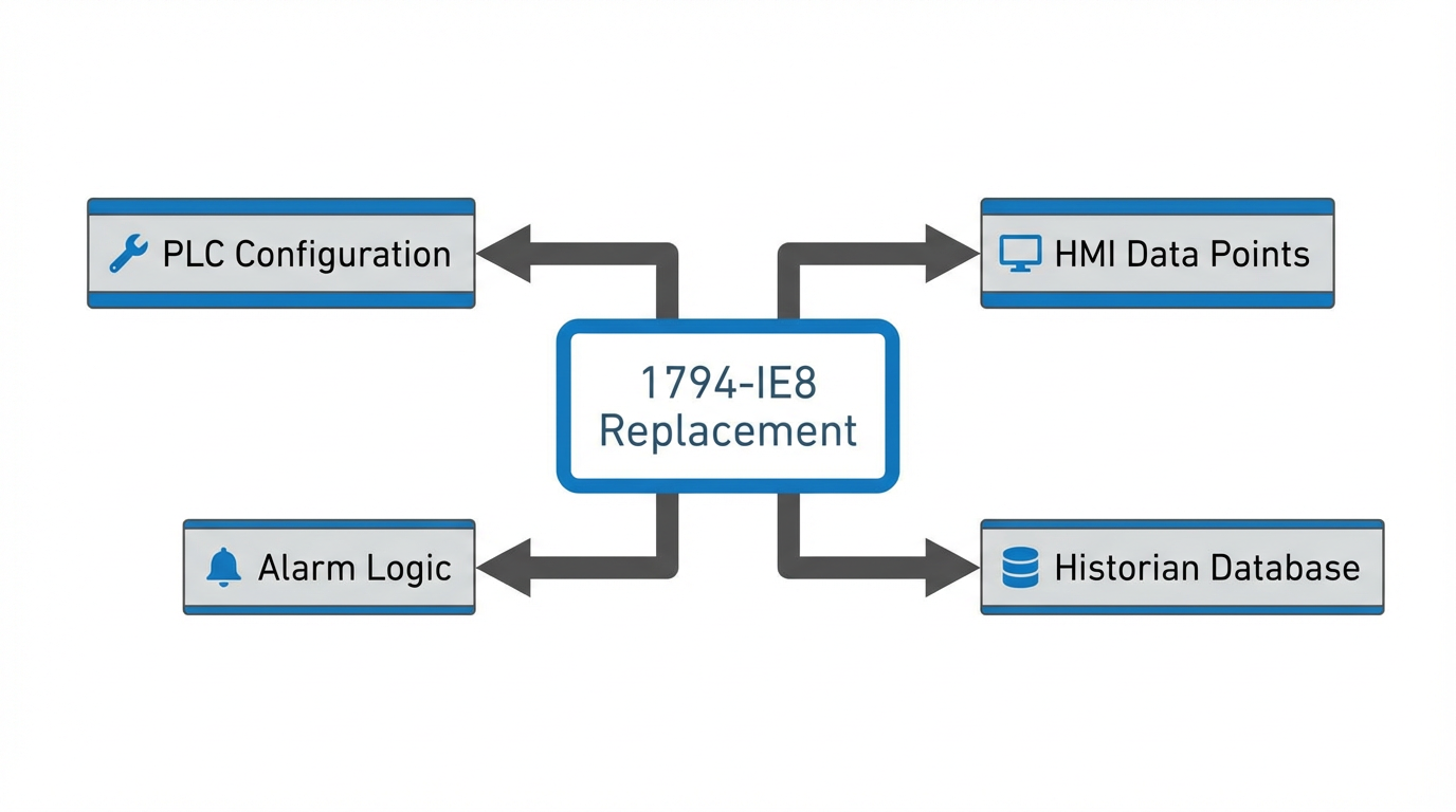
You want to be just as disciplined at the system level as Rockwell is in that PCDC matrix.
Pros and Cons of Cross-Replacing a 1794-IE8
After you do a cold-eyed review of the technical data, the question becomes: should you cross-reference at all, or stay with the original module?
Staying with the 1794-IE8 inside the FLEX ecosystem has obvious advantages. You get guaranteed mechanical and electrical compatibility with the existing terminal bases and adapters, and you stay within the hazard and environmental envelope Rockwell has documented. Your maintenance team keeps a consistent spares strategy, your training materials stay valid, and your PLC code usually only needs minor adjustments when modules are added or replaced, not when you swap in a new platform.
On the other hand, there are circumstances where a functional equivalent in a different platform is worth considering, such as a plant that is standardizing on a newer distributed I/O system or consolidating vendors. In those cases, the 1794-IE8 becomes your benchmark: any new module must match the signal ranges, accuracy, response, and approvals described earlier. You also have to budget time and effort to revise PLC logic, HMI points, diagnostics, and maintenance procedures, because none of that will be truly “equivalent” out of the box.
From a risk perspective, the strongest argument for cross-replacing the 1794-IE8 is usually lifecycle and supply security, not minor performance gains. When you do move away from it, make sure the project is treated as an engineered migration, not as a parts substitution.
Practical Advice from the Field
Based on the Rockwell and third‑party documentation summarized earlier, and many projects where FLEX I/O has been the backbone of a distributed system, there are several habits that consistently pay off when you are evaluating 1794-IE8 equivalents.
Always start from the official Rockwell Automation documentation for the 1794-IE8 and its analog siblings, particularly the installation and user manual and the technical data sheets. Treat that as your specification baseline. Distributor summaries from organizations like DoSupply, TCI Supply, and Manuals Plus are valuable, but they should confirm and clarify, not replace, the primary documentation.
Document your analog channels thoroughly before making changes. That means capturing the signal type, range, wiring terminal numbers on the FLEX bases, shield terminations, and any special scaling or calibration applied in the controller. Anadi Automation’s guidance on configuring the 1794-IE8—choosing the correct range, applying engineering-unit scaling, and performing calibration—reinforces how important this configuration detail is to accurate measurement.
When you introduce a candidate equivalent, either within FLEX I/O or in another platform, walk through each of the key specification rows described earlier and explicitly confirm the match. If you cannot match a parameter exactly, make a conscious decision about whether the difference is acceptable and document the rationale.
Finally, do not neglect power, grounding, and ESD practices. Rockwell’s guidance on using a zinc-plated, chromate-passivated steel DIN rail for grounding, securing the rail approximately every 7.8 inches, discharging static before handling modules, and avoiding contact with connectors, has been written in blood and downtime over decades of field experience. If an “equivalent” module requires significantly different grounding or ESD handling, factor that into your risk assessment.
FAQ
What is the simplest way to think about an “equivalent” to a 1794-IE8?
In practical terms, an equivalent must accept the same analog current and voltage ranges, provide at least the same resolution and accuracy, withstand the same environment and hazardous-location classification, and integrate mechanically and electrically with your existing wiring and enclosures. If any of those are compromised, you are not dealing with a true equivalent; you are redesigning part of the system.
Are 1794-OE4 and 1794-IE4XOE2 replacements for a 1794-IE8?
They are close relatives rather than direct replacements. The 1794-OE4 is an analog output module and the 1794-IE4XOE2 combines analog inputs and outputs, whereas the 1794-IE8 is pure analog input with eight channels. All three share the same FLEX mechanical platform, environmental ratings, and hazardous-location approvals, so they are easy to mix on the same rail, but they serve different I/O roles.
How critical are the hazardous-location approvals when crossing to another module?
If your panel is in a Zone 2 or Class I, Division 2 area, the approvals are non‑negotiable. The 1794-IE8 and its analog siblings are approved for those environments under specific protection types and temperature codes, and Rockwell imposes special conditions for safe use, including enclosure ratings and transient protection limits. Any equivalent must carry comparable approvals and fit the same safe-use pattern, or you risk undermining the entire hazardous-area classification.
As a systems integrator, I treat the 1794-IE8 not just as a part number, but as a well-defined set of electrical, mechanical, safety, and system behaviors. When you do the same, your cross-reference choices stop being guesswork and become disciplined engineering decisions that keep projects on schedule and plants running safely.
References
- https://www.plctalk.net/forums/threads/1794-flex-io-modules-not-showing-up.76124/
- https://www.artisantg.com/info/AB_1794_Series_Datasheet.pdf?srsltid=AfmBOopEW0q6fiytVWbCTHcIO_r3y3knPmF5Q4vSmuH-JlfAbwK6YgJo
- https://www.ebay.com/itm/335732074994
- https://manuals.plus/allen-bradley/1794-ie8-flex-i-o-input-analog-modules-manual
- https://www.mc-mc.com/Product/allen-bradley-1794-ie8
- https://www.reynoldsonline.com/Product/allen-bradley-1794-ie8
- https://compatibility.rockwellautomation.com/Pages/HandlePrint.aspx?type=1¶ms=56537,56708,56501,56575,56005,55896,52170,53700,55969,56577,56578,56457,55861,56474,56340
- https://docs.rs-online.com/99bb/0900766b8002d91b.pdf
- https://tcisupply.com/allen-bradley-1794-ie8-flex-i-o-analog-input-module/?srsltid=AfmBOorXBaaXNlqJQ8NIvKEs-UTogCW8GGf4yo6bGFZnKo_MC-SDHPx7
- https://anadiautomation202.wixsite.com/1769-if4xof2/post/a-comprehensive-guide-to-the-allen-bradley-1794-ie8-analog-input-module
Keep your system in play!
Top Media Coverage
Categories


Related Products
-
 Bently Nevada Proximitor Probe Extension CableManufacturer: Bently Nevada
 -
 Flex XT 8 Point Analog Input ModuleManufacturer: Allen-Bradley
 -
USB Interface CableManufacturer: Allen-Bradley
-
 Extension CableManufacturer: Bently Nevada
 -
V11-G-BK1,5M-PUR-U-V11-G Accessories (Cables Connectors)Manufacturer: Pepperl + Fuchs
-
Safety Relay 230VAC 50/60HZ 1NO/1NCManufacturer: Pilz
-
Analog Input Module - HARTManufacturer: Allen-Bradley
-
SLC 500 DeviceNet Scanner ModuleManufacturer: Allen-Bradley
-
 Flex 8 Point Analog Input ModuleManufacturer: Allen-Bradley
 -
V11-G-BK10M-PUR-U-V11-G Accessories (Cables Connectors)Manufacturer: Pepperl + Fuchs

Related articles Browse All
-
 amikong NewsSchneider Electric HMIGTO5310: A Powerful Touchscreen Panel for Industrial Automation2025-08-11 16:24:25Overview of the Schneider Electric HMIGTO5310 The Schneider Electric HMIGTO5310 is a high-performance Magelis GTO touchscreen panel designed for industrial automation and infrastructure applications. With a 10.4" TFT LCD display and 640 x 480 VGA resolution, this HMI delivers crisp, clear visu...
 -
 BlogImplementing Vision Systems for Industrial Robots: Enhancing Precision and Automation2025-08-12 11:26:54Industrial robots gain powerful new abilities through vision systems. These systems give robots the sense of sight, so they can understand and react to what is around them. So, robots can perform complex tasks with greater accuracy and flexibility. Automation in manufacturing reaches a new level of ...
 -
 BlogOptimizing PM Schedules Data-Driven Approaches to Preventative Maintenance2025-08-21 18:08:33Moving away from fixed maintenance schedules is a significant operational shift. Companies now use data to guide their maintenance efforts. This change leads to greater efficiency and equipment reliability. The goal is to perform the right task at the right time, based on real information, not just ...


- Q&A
- Policies How to order Part status information Shipping Method Return Policy Warranty Policy Payment Terms
- Asset Recovery
- We Buy Your Equipment. Industry Cases Amikong News Technical Resources Why choose us
- ADDRESS
-
 32D UNITS,GUOMAO BUILDING,NO 388 HUBIN SOUTH ROAD,SIMING DISTRICT,XIAMEN
Leave Your Comment