
-
Please try to be as accurate as possible with your search.
-
We can quote you on 1000s of specialist parts, even if they are not listed on our website.
-
We can't find any results for “”.
How to Select a Servo Drive for Dynamic Motion Control Requirements
When you push a machine into truly dynamic motion—fast indexing, sharp corners, coordinated multi‑axis moves—the servo drive stops being a commodity box and becomes the heart of the system. As a systems integrator who has lived through my share of chattering axes, tripped drives, and hot motors, I can say that most servo drive problems trace back to selection decisions made on day one, not to “mysterious” behavior in the field.
This article walks through how to select a servo drive specifically for demanding, dynamic motion applications. It draws on guidance from manufacturers such as Advanced Motion Controls, Kollmorgen, Festo, Anaheim Automation, ABB, and others, and it is structured the way we think about real projects on the plant floor, not the way catalog pages are organized.
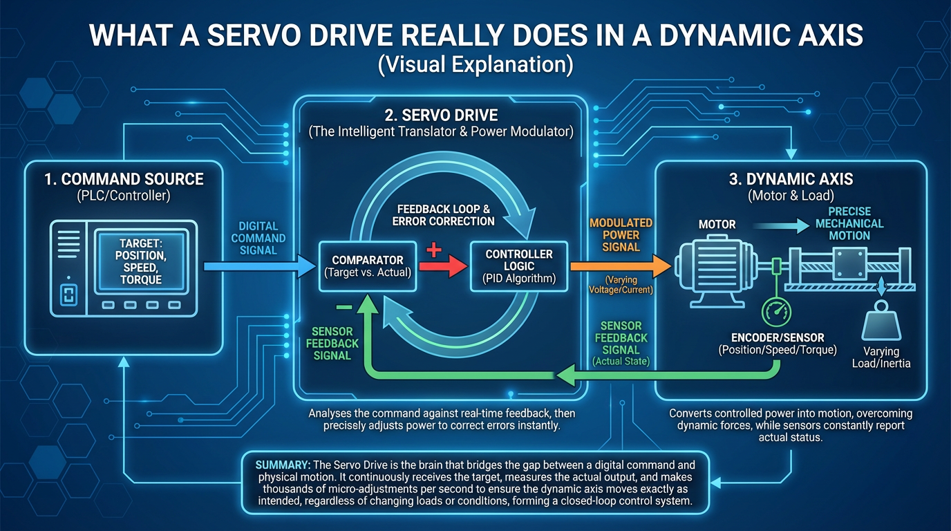
What a Servo Drive Really Does in a Dynamic Axis
A servo system is more than just a motor. As described in servo motor guides from Anaheim Automation and Festo, a servomechanism is a closed-loop system that measures what the axis is actually doing and corrects any error in real time. The servo motor provides torque, the feedback device (often an encoder or resolver) reports position and speed, and the servo drive closes the loops for current, speed, and sometimes position.
In practical terms, the servo drive takes commands from a controller, converts them to pulse‑width‑modulated voltage and current, and regulates the motor so that torque, speed, and position follow the command profile. Motor torque is directly proportional to drive current, and motor speed is proportional to drive voltage, as highlighted in Festo’s and Elmo’s explanations of basic motion systems. The drive’s job is to manage those electrical quantities within safe limits while reacting fast enough to keep up with the mechanical dynamics.
Dynamic motion control pushes the servo drive hard. Rapid acceleration and deceleration, frequent reversals, and complex trajectories demand both high peak current and fast, well‑tuned control loops. That is why drive selection must be anchored in the motion and the mechanics, not in marketing specs.
Start with the Motion and the Mechanics
Every serious drive selection starts with the load and the motion profile. Anaheim Automation’s motion control guidance and servomotor selection notes from SEW‑Eurodrive emphasize the same first principles.
You begin by defining the mechanical power required: torque multiplied by speed over the full motion cycle. That includes acceleration, constant‑speed moves, deceleration, and dwell. For rotary axes, you also calculate the system inertia and the reflected inertia at the motor shaft. Industry guidance from SEW‑Eurodrive and Control Engineering recommends keeping the load‑to‑motor inertia ratio in a modest range, often somewhere between roughly three‑to‑one and ten‑to‑one depending on the drive and performance goals. Very high ratios are controllable but make tuning much harder and slow the response.
As ABB’s drive dimensioning guide and the DC motor selection article from Automate.org both note, designing from mechanical power alone is dangerous. A twenty‑five watt application can still overheat a forty watt motor if the torque demand exceeds the motor’s rated torque. In real machines, friction, misalignment, and changing payloads mean the torque you see during acceleration and corners is often higher than what you calculate on paper. That same torque translates directly into current that the drive must deliver without tripping or cooking the motor.
For dynamic motion, the motion profile itself becomes a design constraint. Short, high‑torque bursts and rapid start‑stop sequences drive up the root‑mean‑square torque and current. ABB recommends evaluating RMS current over the duty cycle rather than looking only at peak values, because thermal loading in both the motor and the drive depends on that RMS value. When you do this up front, you end up with a motor that can survive the cycle and a drive that can feed it.
Only after you have a credible motor choice—power, speed, inertia, and torque profile—does it make sense to talk about servo drives.
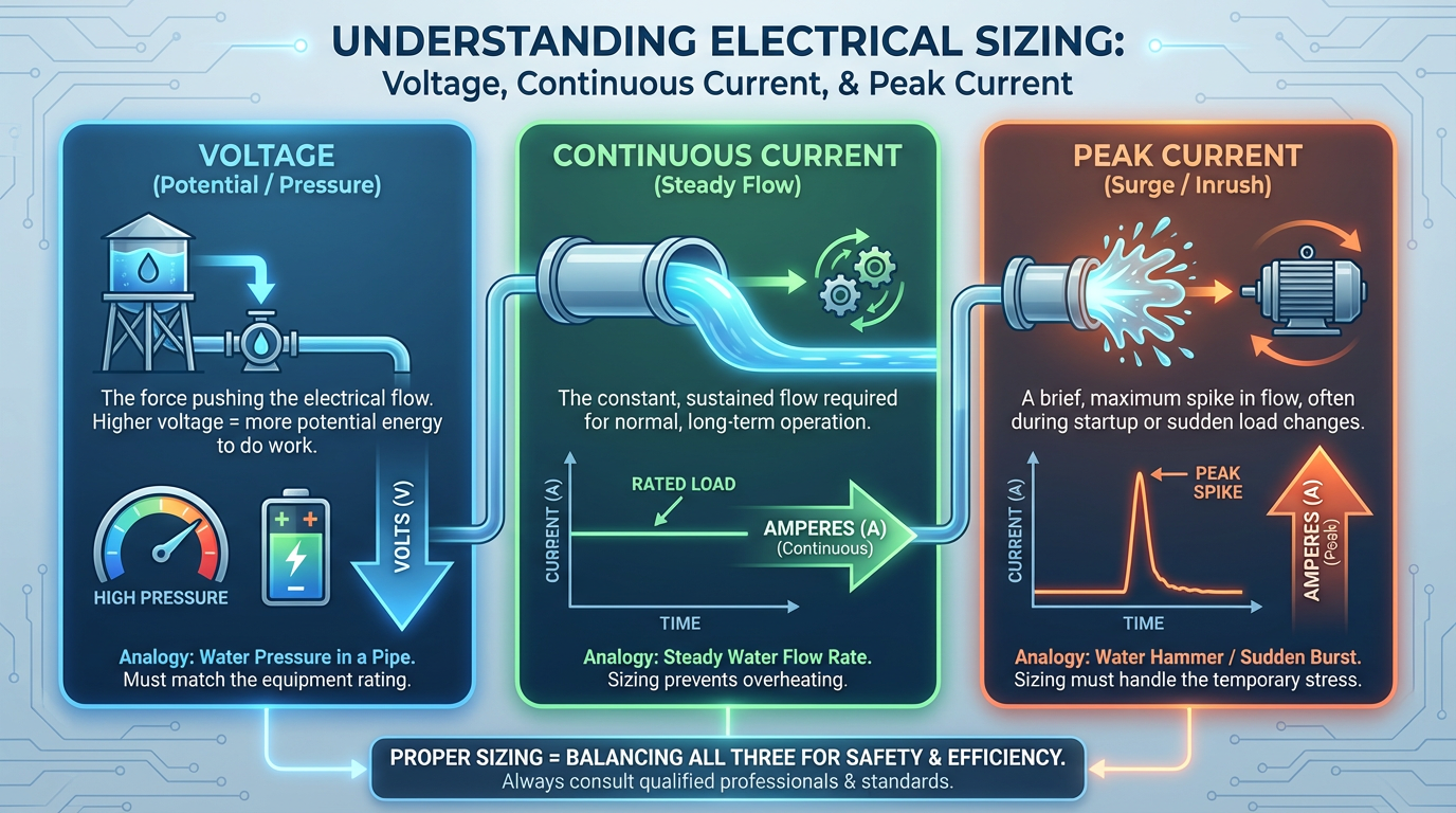
Electrical Sizing: Voltage, Continuous Current, and Peak Current
Matching the Supply and DC Bus Voltage
Advanced Motion Controls and Anaheim Automation both stress that available supply voltage is one of the first filters in any drive selection. Facilities might offer around 110 or 220 volts AC single‑phase, sometimes higher three‑phase, or DC from a battery or power supply. Servo drives are designed to accept a specific input range and create a DC bus that powers the motor.
If your plant distribution, control cabinet, or mobile platform provides a given voltage, the practical path is to select a motor family that matches that level and then choose a drive designed for that same line. Kollmorgen’s servo drive guidance, for example, discusses motors rated for about 240 volts AC and matching drives whose input line voltage produces an appropriate DC bus for those motors. For dynamic applications, you also want a bit of voltage headroom so that the drive can maintain commanded speed under load without saturating.
Voltage compatibility is not just about spinning the motor. Festo points out that selecting a servo motor and drive whose voltage matches the control system and power source improves energy efficiency and reduces the risk of damaging either component with over‑ or under‑voltage conditions.
Continuous Current: The Daily Workhorse
Servo drives are fundamentally current sources. Their continuous current rating is the most important number on the label for thermal and long‑term reliability. It tells you how much torque they can deliver indefinitely, assuming normal cooling.
Kollmorgen describes a straightforward example. A motor needs around three amperes continuous and about five amperes peak at approximately 240 volts AC. A drive rated for the same voltage and three amperes continuous typically offers significantly more peak current for short bursts, often on the order of two to three times the continuous rating. In this situation, that drive easily meets the motor’s continuous and peak needs, so it is a sensible match.
Festo and Automate.org both emphasize that the average or RMS torque of the motion cycle must stay below the motor’s continuous torque rating. Because torque is proportional to current, the RMS current the drive supplies must stay below its own continuous rating. When selecting for dynamic duty, the safest path is to compute the RMS torque and current and then pick a drive with some margin, rather than simply matching nameplate continuous values.
Peak Current and Overload Capability
Dynamic motion exposes the limitations of a drive’s overload capacity. Support from Kollmorgen and from the DC motor selection paper explains that most servo drives supply two to three times their continuous current for short periods, typically on the order of seconds. That peak current is what allows the motor to accelerate rapidly, overcome stiction, and hold tight tolerances during sharp corners.
Kollmorgen provides another example in which a motor is rated around two amperes continuous and eight amperes peak for roughly one and a half seconds. A drive with a continuous rating of three amperes but a peak capability around nine amperes can still be used safely with that motor, provided you respect the duty cycle. In that case, it is the motor that limits the system, not the drive, and the integrator must monitor temperature and possibly adjust the motion profile so as not to overstress the motor while the drive still has capacity left.
The Automate.org article on DC motor selection notes that DC motors can typically handle two to three times their nominal torque for several seconds without overheating. Servo motors and drives behave similarly in principle, though you must rely on the manufacturer’s overload curves. Drives and motors are usually specified with both continuous and short‑time overload ratings; ABB mentions heavy‑duty ratings that allow about one hundred fifty percent current for about a minute every ten minutes. These numbers matter greatly when you are sizing for high‑acceleration axes.
The bottom line is that for dynamic motion, you choose a drive whose continuous current exceeds the calculated RMS demand with some margin, and whose peak current comfortably covers acceleration and transient loads within the allowed time window.
Control Modes and Dynamic Behavior
Torque, Velocity, and Position Modes
Advanced Motion Controls and Elmo Motion Control describe three core operating modes for servo drives.
In torque or current mode, the drive regulates current to produce a commanded torque while an external controller closes the velocity and position loops. This mode is common in centralized architectures where a powerful motion controller does the heavy lifting. It is useful when you need very direct control over force or torque, for example in tension control.
In velocity mode, the drive maintains a target speed despite load changes. The controller commands speed or a speed profile, and the drive’s internal current loop handles torque as needed. This approach suits conveyors, spindles, traction drives, and some mobile robots where speed regulation is the primary requirement.
In position mode, often with nested loops for current and speed inside the drive, the unit receives position commands and handles everything internally to place the axis precisely. This is the dominant mode for robotics, pick‑and‑place, packaging, and other dynamic positioning tasks. The servo drive executes trajectories, interpolates motion, and applies its own advanced tuning tools.
For fast, high‑precision motion, position mode in an intelligent digital drive is usually the most robust option because the feedback and control loops sit right next to the power electronics, minimizing latency and giving the drive access to all the details it needs for optimal tuning.
Inertia Ratios and Tuning Effort
As Control Engineering and SEW‑Eurodrive’s selection notes underline, the ratio of load inertia to motor inertia is a central design parameter. Many vendors recommend staying around ten‑to‑one or better for general applications, with tighter ratios such as two‑to‑one or five‑to‑one for very fast positioning.
These inertia ratios do not directly change the drive’s electrical ratings, but they have a huge impact on control performance and tuning difficulty. Control Engineering recounts a case with a very high inertia mismatch, on the order of more than a hundred‑to‑one, that required hours of manual tuning to meet performance needs. At such ratios, every small mechanical disturbance shows up as oscillation, and you quickly run into the limits of the drive’s control algorithms.
Digital drives with advanced tuning tools, feedforward features, and gain scheduling can do impressive work stabilizing high‑inertia systems, but they cannot rewrite the laws of physics. For dynamic motion, you typically want inertia ratios well within the range that your chosen drive vendor supports, and you must confirm that your servo drive’s tuning tools are up to the job.

Analog vs Digital Drives for Dynamic Requirements
Elmo Motion Control offers a clear distinction between analog and digital servo drives that is directly relevant if your application demands fast, complex motion.
Analog drives use purely analog circuitry and usually accept a simple command such as a plus‑minus ten volt signal. They can drive both brushed and brushless motors, are compact and robust, offer very low latency, and are attractive for cost‑sensitive, relatively simple uses such as traction on automated vehicles. The downside is that they require manual calibration with trim potentiometers. In multi‑axis dynamic systems, that tuning can consume hours, and analog drives cannot adapt automatically to changing loads or resonance conditions.
Digital drives incorporate processors and memory. They use software for tuning and configuration, support high update rates, and can implement advanced features such as autotuning, adaptive control under changing inertia, and sophisticated internal motion profiles. Some digital drives also include analog input ports so they can serve as drop‑in replacements for older analog units while you migrate the control system.
For highly dynamic motion control—multi‑axis robotics, tight synchronized packaging lines, aggressive cam profiles—the flexibility and diagnostics of digital drives nearly always outweigh their additional cost and power consumption. The ability to tweak gains in software, capture torque‑speed samples in real time, and run structured autotuning procedures dramatically reduces commissioning time and improves repeatability, as reflected in the Kinco and Elmo drive software features described by Anaheim Automation and Elmo.
The comparison can be summarized as follows.
| Attribute | Analog servo drive | Digital servo drive |
|---|---|---|
| Command and tuning | Voltage command, manual potentiometers | Software‑based commands, autotuning, advanced control functions |
| Latency | Very low | Low, but processing dependent |
| Adaptation to load change | Fixed gains, no built‑in adaptation | Can adapt to varying load inertia and friction via software |
| Complexity and cost | Lower cost and simpler electronics | Higher cost and complexity, but greater capability |
| Suitability for dynamics | Adequate for simple, predictable motion | Strong fit for complex, high‑performance dynamic motion |

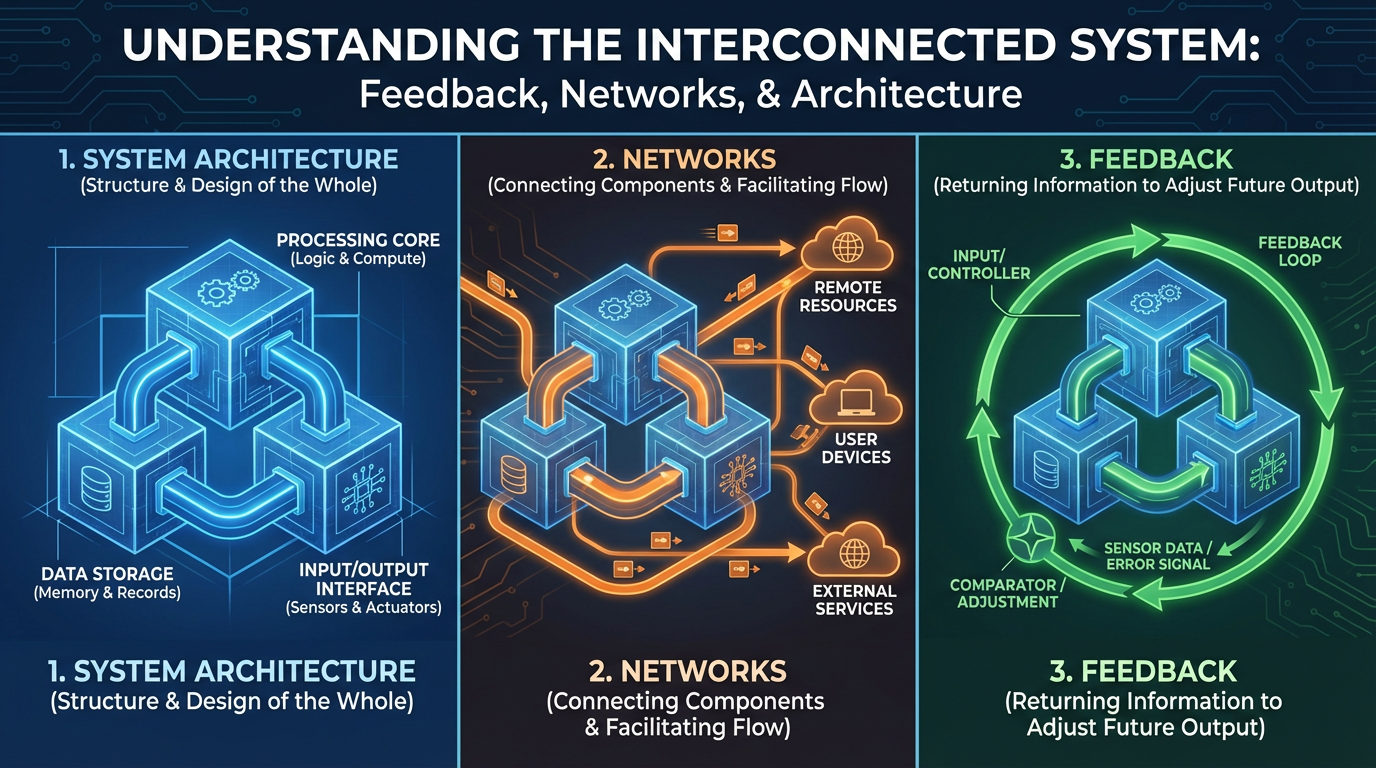
Feedback, Networks, and System Architecture
Feedback Device Compatibility
Servo drives must understand the feedback devices attached to the motor. Anaheim Automation’s servo motor guide notes that encoders are the default choice in most applications because they are accurate and easy to integrate, while resolvers are extremely rugged and preferred for harsh environments and long life.
Kollmorgen and Control Engineering both stress that the drive’s feedback interfaces must match the motor’s encoder or resolver. If you attempt to pair a resolver‑equipped motor with a drive that only accepts digital encoders, you either end up buying external conversion hardware or you do not get a working system.
From a dynamic‑motion standpoint, feedback fidelity and latency directly affect how tight you can tune the loops. High‑resolution encoders and clean, well‑shielded feedback wiring let the servo drive run higher gains without noise‑induced oscillations. Many modern digital drives include diagnostics for encoder or resolver health so you can quickly identify feedback issues during commissioning.
Networks and Distributed Intelligence
Advanced Motion Controls, RoboticsTomorrow, and Control Engineering all describe how digital servo drives increasingly act as intelligent networked devices rather than simple amplifiers.
In a centralized architecture, a motion controller closes the position and sometimes the velocity loops, while the drive simply regulates current. This structure often uses analog commands, step‑and‑direction signals, or simpler fieldbuses such as CANopen or Modbus. It can work well when the controller has enough computational power and the system is modest in scale.
Distributed architectures push more intelligence into each drive. The drives close nested loops and sometimes run entire motion profiles locally, while a master controller broadcasts high‑level commands over a real‑time network. Ethernet‑based networks such as EtherCAT, PROFINET, Ethernet Powerlink, or Ethernet/IP, as referenced by Advanced Motion Controls and RoboticsTomorrow, enable tight synchronization and reduce cabling by daisy‑chaining axes.
For dynamic multi‑axis systems—robotic cells, high‑speed packaging, printing, or coordinated conveyors—real‑time Ethernet networking and intelligent drives are often the cleanest way to achieve synchronized motion with manageable wiring and controller load. The choice of protocol usually follows plant standards, but when you have freedom, you weigh real‑time performance, vendor support, and configuration complexity.
Form Factor, Environment, and Safety
Servo drives come in different mechanical packages, and that matters once you leave the comfort of a control cabinet. Advanced Motion Controls lists panel‑mount drives for traditional enclosures, plug‑in PCB drives for embedded or very compact systems, and rugged vehicle‑mount units for mobile robots and harsh environments. Size is no longer a strict proxy for power; many modern micro‑sized drives rival older, physically larger units.
Festo, ABB, and CSK’s linear servo drive article all make the point that environment and integration constraints are as important as pure electrical ratings. If your machine lives in a washdown or food‑grade environment, motors and drives may need high ingress‑protection ratings, stainless housings, or special coatings. If ambient temperatures are high, thermal derating of both the motor and the drive must be considered. Control Engineering notes that brushless servo motor housings can legitimately run around 212 to 257 degrees Fahrenheit when correctly sized, which feels extremely hot to the touch but is normal for the design; proper instrumentation and monitoring, not hand feel, should guide your thermal decisions.
Safety is also tightly coupled to drive choice. RoboticsTomorrow highlights the importance of overload protection inside the drive, proper grounding, and integration of emergency‑stop circuits. ABB’s drive guidelines emphasize handling regenerative braking energy safely, whether through braking resistors or regenerative units, especially when dynamic braking is frequent. Discussions in the LinuxCNC community about advanced PWM drives and reverse braking also remind us that aggressive stopping strategies can produce large DC bus voltage overshoots, which not every drive is designed to tolerate.
When you select a servo drive for dynamic motion, you are implicitly choosing how it will behave during faults, overloads, and stops. That should be a deliberate design decision, not an afterthought.
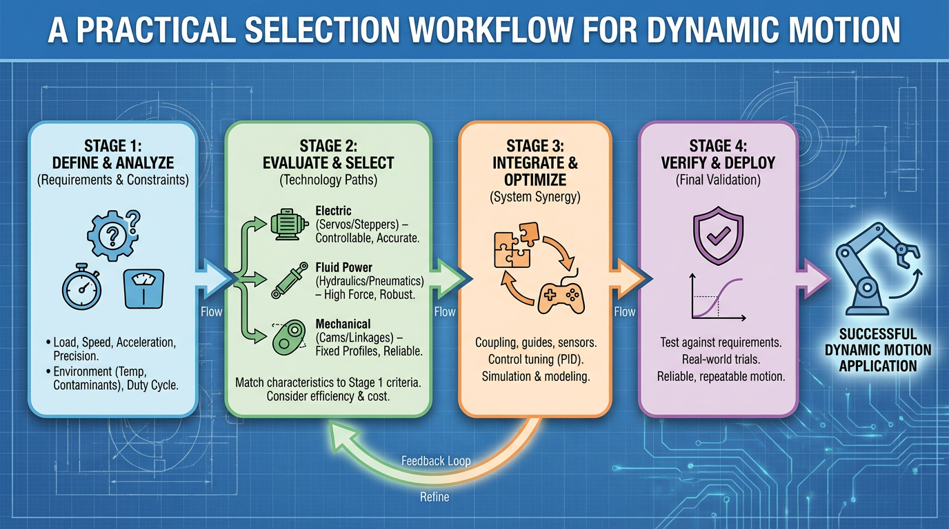
A Practical Selection Workflow for Dynamic Motion
In practice, I approach dynamic motion drive selection as an iterative workflow rather than a one‑shot calculation. The steps align closely with the processes described by Festo, Anaheim Automation, ABB, and several servo drive vendors.
I begin by clarifying the motion: travel distances, angles, cycle times, accelerations and decelerations, and any external forces such as gravity or cutting forces. From this, I calculate the mechanical torque and speed profile, including RMS values and peaks. I pay particular attention to vertical or overhauling axes, where gravity adds constant torque and safety requirements, echoing the caution from Festo and servomotor selection literature.
Next, I model the load inertia and its reflection through any gearboxes or belt reductions. If the load‑to‑motor inertia ratio is outside the comfortable range that Control Engineering and SEW‑Eurodrive describe, I either change gear ratio or move to a different motor frame size. I also apply a sensible torque margin; Anaheim Automation recommends around fifty percent torque margin above the calculated minimum to cover friction, mechanical wear, and transient disturbances, while warning that excessive oversizing adds cost with little benefit.
Once the motor family looks reasonable, I examine the available supply voltage and choose a drive voltage class that fits the facility. Matching motor and drive voltage ratings, as Festo and Advanced Motion Controls advise, reduces both risk and complexity.
Then I size the servo drive electrically. I match the drive’s continuous current to the motor’s continuous current requirement plus some headroom, verifying that RMS current for the motion cycle does not exceed the drive’s continuous rating. I also check that the drive’s peak current can handle motor peak current demands within the specified overload duration. Kollmorgen’s examples are helpful here because they show that it is acceptable for the drive to be somewhat “stronger” than the motor, as long as motion profiles and protections prevent the motor from being over‑stressed.
In parallel, I verify that the drive supports the feedback device I intend to use, whether that is an encoder or resolver as Anaheim Automation describes, and that its operating mode (torque, velocity, or position) matches my control architecture. For highly dynamic axes, I lean toward digital drives with internal position loops and rich tuning features, consistent with Elmo’s and Control Engineering’s discussion of autotuning and feedforward.
Only then do I look at form factor, network options, environmental sealing, safety functions, and vendor software tools. Tools such as Festo’s electric motion sizing or the various selector utilities from servo drive manufacturers are valuable for validating hand calculations and exploring alternatives. At this stage, I also consider whether a pre‑matched motor‑drive package from the same vendor might reduce integration risk, a preference supported by user surveys cited in Control Engineering and by Anaheim Automation’s recommendation of pre‑engineered motion packages.
I typically loop through these steps at least once, updating motor and drive choice as I refine inertia assumptions, load details, and duty cycles. Real machines rarely match the first spreadsheet you build.
Common Mistakes I See in Dynamic Applications
Several recurring errors show up in the field when teams select servo drives for dynamic motion control. They are avoidable once you know what to watch for.
One common mistake is sizing the drive purely by continuous power or current and neglecting peak demands. That leads to drives that run fine in slow jog tests but trip on overcurrent or following error the moment you enable production speeds. Kollmorgen’s emphasis on peak‑to‑continuous torque ratio and the limited time window for peak current is a direct response to this trap.
Another error is ignoring inertia ratios and assuming the drive’s autotuning will fix everything. As Control Engineering’s example of a very high inertia mismatch shows, you can sometimes make such systems behave, but only at the cost of long tuning sessions and reduced performance. Drives with advanced feedforward and learning tools help, yet they are not a substitute for sound mechanical sizing.
A third pitfall is mismatching feedback and communication standards. I have seen projects stalled because a team bought a resolver‑equipped motor and a drive that only understood digital encoders, or selected drives with a network protocol that the plant PLC platform simply did not support. The servo drive selection guides from Advanced Motion Controls and the robotics integration article both underline the need to align fieldbus choice with the broader control architecture rather than choosing in isolation.
Finally, teams sometimes overspecify the drive “just to be safe,” doubling or tripling current ratings out of fear. Anaheim Automation and ABB both show that moderate safety factors are prudent but that excessive oversizing wastes money and can even degrade control resolution in lower‑torque regions. The goal is not the biggest drive; it is the right drive with the right margins for your specific dynamic profile.

Brief FAQ
How much safety margin should I design into servo drive current?
Anaheim Automation’s motion control guidance recommends applying roughly a fifty percent torque margin above the calculated minimum to cover friction, wear, and transient events, while cautioning that margins much above one hundred percent rarely add real benefit. Because torque is proportional to current, a similar approach works for drive current. You want enough headroom for unexpected conditions and tuning iterations, but not so much that you double the size and cost of the hardware without cause.
Is it acceptable to use a higher‑current drive with a smaller motor?
Yes, within limits. Kollmorgen describes a case where a motor rated around two amperes continuous and eight amperes peak is paired with a drive rated roughly three amperes continuous and nine amperes peak. That configuration is acceptable because the drive’s current limit is set and the motion profile respects the motor’s thermal limits. In such situations, you treat the motor as the limiting component and ensure that drive protections and control software prevent currents above what the motor can safely handle.
When should I insist on a matched motor and drive from the same vendor?
Control Engineering reports that a strong majority of users prefer to buy motors and drives as integrated systems rather than mixing vendors, and Anaheim Automation highlights the advantages of pre‑matched packages. For complex or highly dynamic applications, using a motor and drive from the same manufacturer simplifies wiring, feedback compatibility, network configuration, and tuning, and it often gives you better support from the vendor’s application engineers. In simpler or retrofit scenarios, mixing components can still work, but it demands more careful checking of all electrical, feedback, and communication interfaces.
In dynamic motion control, the servo drive is where your mechanical ambitions meet electrical reality. If you start from the motion, respect inertia and torque, match voltage and current thoughtfully, and choose the right control architecture and feedback, the servo drive becomes a reliable project partner instead of an unpredictable black box. That is the kind of design that runs day in and day out, long after the startup team has gone home.
References
- https://pmc.ncbi.nlm.nih.gov/articles/PMC9602786/
- https://www.automate.org/tech-papers/dc-motor-selection-for-dynamic-motion-control-applications
- https://forum.linuxcnc.org/27-driver-boards/27866-advanced-motion-control-servo-drive-choice
- https://www.dinamikotomasyon.net/en/blog/servo-motor-and-driver-sets
- https://blog.seweurodrive.com/navigating-servomotor-selection-a-technical-guide
- https://www.solisplc.com/servo-motor
- https://www.a-m-c.com/how-to-select-a-servo-drive/
- https://www.controleng.com/servo-system-application-tips/
- https://www.designnews.com/motors-actuators-conveyors/stepper-vs-servo-motors-pros-cons-how-to-choose-the-right-one
- https://motioncontrol.blog/how-to-choose-ac-servo-motors-by-axis-requirements/
Keep your system in play!
Top Media Coverage
Categories


Related Products
-
 DIGITAL OUTPUT MODULEManufacturer: Siemens
 -
CENTRAL PROCESSING UNITManufacturer: Siemens
-
 TEACH PENDANTManufacturer: ABB
 -
 CP-8050 Master ModuleManufacturer: Siemens
 -
 DIG OUTP RELManufacturer: Siemens
 -
POWER SUPPLY MODULEManufacturer: Honeywell
-
 Network Interface ModuleManufacturer: Emerson
 -
 Power CardManufacturer: ABB
 -
BASE ASSEMBLYManufacturer: Emerson
-
3300 XL 8 mm Proximity ProbesManufacturer: Bently Nevada

Related articles Browse All
-
 amikong NewsSchneider Electric HMIGTO5310: A Powerful Touchscreen Panel for Industrial Automation2025-08-11 16:24:25Overview of the Schneider Electric HMIGTO5310 The Schneider Electric HMIGTO5310 is a high-performance Magelis GTO touchscreen panel designed for industrial automation and infrastructure applications. With a 10.4" TFT LCD display and 640 x 480 VGA resolution, this HMI delivers crisp, clear visu...
 -
 BlogImplementing Vision Systems for Industrial Robots: Enhancing Precision and Automation2025-08-12 11:26:54Industrial robots gain powerful new abilities through vision systems. These systems give robots the sense of sight, so they can understand and react to what is around them. So, robots can perform complex tasks with greater accuracy and flexibility. Automation in manufacturing reaches a new level of ...
 -
 BlogOptimizing PM Schedules Data-Driven Approaches to Preventative Maintenance2025-08-21 18:08:33Moving away from fixed maintenance schedules is a significant operational shift. Companies now use data to guide their maintenance efforts. This change leads to greater efficiency and equipment reliability. The goal is to perform the right task at the right time, based on real information, not just ...


- Q&A
- Policies How to order Part status information Shipping Method Return Policy Warranty Policy Payment Terms
- Asset Recovery
- We Buy Your Equipment. Industry Cases Amikong News Technical Resources Why choose us
- ADDRESS
-
 32D UNITS,GUOMAO BUILDING,NO 388 HUBIN SOUTH ROAD,SIMING DISTRICT,XIAMEN
Leave Your Comment